

Eaton 645M Series, EL-615M-1-EU, EL-615M-1-US, ELPRO 645M-1 User Manual
Broadband 4g/LTE Cellular Router
www.aarrss.com

Copyright notice
© 2016 Eaton. All rights reserved.
Eaton reserves the right to modify the equipment, its specification or this manual without prior notice, in the interest of improving
performance, reliability, or servicing. At the time of publication all data is correct for the operation of the equipment at the voltage
and/or temperature referred to. Performance data indicates typical values related to the particular product. Product updates may
result in differences between the information provided in this manual and the product shipped. For access to the most current
product documentation and application notes, visit www.Eaton.com.
No part of this documentation or information supplied may be divulged to any third party without the express written consent of
Eaton. Products offered may contain software which is proprietary to Eaton. The offer or supply of these products and services does
not include or infer any transfer of ownership.
Modem use
The 645M Series modems are designed and intended for use in fixed and mobile applications. “Fixed” assumes the device is
physically secured at one location and not easily moved to another location. Please keep the cellular antenna at a safe distance from
your head and body while the modem is in use.
Regulatory statements
Note: This equipment has been tested and found to comply with the limits for a Class B digital device, pursuant to part -15 of the
FCC Rules. These limits are designed to provide reasonable protection against harmful interference in a residential installation.
This equipment generates, uses and can radiate radio frequency energy and, if not installed and used in accordance with the
instructions, may cause harmful interference to radio communications. However, there is no guarantee that interference will not
occur in a particular installation. If this equipment does cause harmful interference to radio or television reception, which can be
determined by turning the equipment off and on, the user is encouraged to try to correct the interference by one or more of the
following measures: i) Reorient or relocate the receiving antenna. II) Increase the separation between the equipment and receiver.
III) Connect the equipment into an outlet on a circuit different from that to which the receiver is connected. Iv) Consult the dealer or
an experienced radio/TV technician for help.
This device complies with Industry Canada licence-exempt RSS standard(s). Operation is subject to the following two conditions:
(1) this device may not cause interference, and (2) this device must accept any interference, including interference that may cause
undesired operation of the device.
Le présent appareil est conforme aux CNR d’Industrie Canada applicables aux appareils radio exempts de licence. L’exploitation est
autorisée aux deux conditions suivantes : (1) l’appareil nedoit pas produire de brouillage, et (2) l’appareil doit accepter tout brouillage
radioélectrique subi, même si le brouillage est susceptible d’en compromettre le fonctionnement.
Under Industry Canada regulations, this radio transmitter may only operate using an antenna ofa type and maximum (or lesser)
gain approved for the transmitter by Industry Canada. To reduce potential radio interference to other users, the antenna type and
its gain should be so chosen that the equivalent isotropically radiated power (e.i.r.p.) is not more than that necessary for successful
communication.
Conformément à la réglementation d’Industrie Canada, le présent émetteur radio peut fonctionner avec une antenne d’un type et
d’un gain maximal (ou inférieur) approuvé pour l’émetteur par Industrie Canada. Dans le but de réduire les risques de brouillage
radioélectrique à l’intention des autres utilisateurs, il faut choisir le type d’antenne et son gain de sorte que la puissance isotrope
rayonnée équivalente (p.i.r.e.) ne dépasse pas l’intensité nécessaire à l’établissement d’une communication satisfaisante.
ii 645M 4G/LTE CELLULAR ROUTER MN032003EN March 2017 www.eaton.com

Broadband 4g/LTE Cellular Router
Contents
1 Product overview ....................................................................... 1
1.1 Module Identification ............................................................................. 1
1.2 Features and benefits of the 645M broadband 4G LTE cellular router ........................................ 1
1.3 General specifications ............................................................................. 2
1.4 Mechanical specifications .......................................................................... 3
1.5 Order information ................................................................................ 3
1.5.1 Mounting brackets ......................................................................... 3
1.6 External connectors .............................................................................. 4
1.7 Antenna ........................................................................................ 5
1.8 Power cable pinout ............................................................................... 5
1.9 RS-232 / RS-485 serial port ......................................................................... 5
1.10 RESET button .................................................................................. 5
2 Getting started ......................................................................... 6
2.1 Package contents ................................................................................ 6
2.2 Device connections .............................................................................. 6
2.3 Lan configuration ................................................................................ 6
2.4 Cellular connections .............................................................................. 6
3 645M web interface ..................................................................... 7
3.1 Unit status. ..................................................................................... 7
3.1.1 Status ................................................................................... 7
3.1.2 System ..................................................................................10
3.1.3 Basic settings .............................................................................11
3.2 Cell connection ..................................................................................11
3.2.1 Carrier ..................................................................................11
3.2.2 Settings ................................................................................ 13
3.2.3 Dynamic DNS ........................................................................... 14
3.2.4 System monitor .......................................................................... 15
3.2.5 Other settings ........................................................................... 16
3.2.6 Lan settings ............................................................................. 16
3.3 Router .........................................................................................17
3.3.1 Port forwardS ............................................................................17
3.3.2 DMZ .................................................................................. 18
3.3.3 IP filtering .............................................................................. 19
3.3.4 MAC filtering ............................................................................ 21
3.3.5 Static routes ............................................................................ 22
3.3.6 ARP ................................................................................... 22
3.3.7 IP passthrough .......................................................................... 23
3.4 Security ...................................................................................... 25
3.4.1 Status ................................................................................. 25
3.4.2 PPTP .................................................................................. 26
3.4.3 IPsec .................................................................................. 27
3.4.4 GRE ................................................................................... 29
3.4.5 OpenVPN ............................................................................... 30
645M 4G/LTE CELLULAR ROUTER MN032003EN March 2017 www.eaton.com
iii

Broadband 4g/LTE Cellular Router
3.5 Serial ......................................................................................... 31
3.5.1 External serial ........................................................................... 31
3.6 Diagnostics .................................................................................... 33
3.6.1 Sms ................................................................................... 33
3.6.2 Rssi traps. . . . . . . . . . . . . . . . . . . . . . . . . . . . . . . . . . . . . . . . . . . . . . . . . . . . . . . . . . . . . . . . . . . . . . . . . . . . . . . 34
3.6.3 Syslog settings .......................................................................... 35
3.6.4 System log ............................................................................. 36
3.6.5 Kernel log .............................................................................. 36
3.7 I/O settings .................................................................................... 37
3.7.1 Status .................................................................................. 37
3.7.2 Snmp .................................................................................. 38
3.7.3 Settings ................................................................................ 39
3.7.4 Labels .................................................................................. 42
3.8 Admin ........................................................................................ 43
3.8.1 Access ................................................................................. 43
3.8.2 Remote admin ........................................................................... 44
3.8.3 RADIUS ................................................................................ 44
3.8.4 Firmware update ......................................................................... 45
3.8.5 System reset ............................................................................ 46
4 IP addressing ......................................................................... 46
4.1 Overview ..................................................................................... 46
4.2 IP Addressing tutorial ............................................................................ 46
4.3 Private versus Ppublic IP addresses ................................................................. 46
4.4 Port forwarding ................................................................................. 47
4.5 DMZ ......................................................................................... 47
4.6 Friendly IP address .............................................................................. 47
5 IPsec and VPN pass-phrough deployment guide ............................................ 48
5.1 Benefits of IPsec. ............................................................................... 48
5.2 Configuration summary .......................................................................... 48
5.2.1 Case #1: 645M configured IPsec client ....................................................... 48
5.2.2 Case #2 645M configured to use a DMZ for VPN pass-through .................................... 52
6 User I/O port. . . . . . . . . . . . . . . . . . . . . . . . . . . . . . . . . . . . . . . . . . . . . . . . . . . . . . . . . . . . . . . . . . . . . . . . . . 53
6.1 Electrical characteristics .......................................................................... 53
6.2 Input circuit for analog inputs ...................................................................... 54
6.3 Simplified circuit for digital input ................................................................... 54
6.4 Simplified circuit for open collecter outputs ........................................................... 54
Appendix A: Abbreviations and definitions ................................................... 55
Appendix B: Mechanical specifications ....................................................... 56
Appendix C: UL Installation instructions ..................................................... 58
Appendix D: Support note – 615/645M cellular modem SMS .................................... 59
Appendix E: Service and support and warranty statement ...................................... 62
iv
645M 4G/LTE CELLULAR ROUTER MN032003EN March 2017 www.eaton.com

IC ICES-003 standard compliance notice:
CAN ICES-3 (B)/NMB-3(B)
IMPORTANT
Maintain a distance of at least 20 cm (8 inches) between the
transmitter antenna and any person while in use. This modem
is designed for use in applications that observe the 20 cm
separation distance.
Interference issues
Avoid possible radio frequency (RF) interference by following
these guidelines:
•
The use of cellular telephones or devices in aircraft is illegal.
Use in aircraft may endanger operation and disrupt the
cellular network. Failure to observe this restriction may result
in suspension or denial of cellular services to the offender,
legal action, or both
•
Do not operate in the vicinity of gasoline or diesel fuel
pumps unless use has been approved or authorized
•
Do not operate in locations where medical equipment that
the device could interfere with may be in use
•
Do not operate in fuel depots, chemical plants, or blasting
areas unless use has been approved and authorized
•
Use care if operating in the vicinity of protected personal
medical devices, i.e., hearing aids and pacemakers
•
Operation in the presence of other electronic equipment
may cause interference if equipment is incorrectly protected.
Follow recommendations for installation from
equipment manufacturers
Mobile application safety
•
Do not change parameters or perform other maintenance of
the ELPRO 645M while driving
•
Road safety is crucial. Observe National Regulations for
cellular telephones and devices in vehicles
•
Avoid potential interference with vehicle electronics by
correctly installing the ELPRO 645M modem. Eaton
recommends installation by a professional
UL Listed models only
Broadband 4g/LTE Cellular Router
Maintain a distance of at least 20 cm (8 inches) between the
transmitter antenna and any person while in use. This modem
is designed for use in applications that observe the 20 cm
separation distance.
WARNING
EXPLOSION HAZARD, do not connect while circuit is live
unless area is known to be non-hazardous.
645M 4G/LTE CELLULAR ROUTER MN032003EN March 2017 www.eaton.com
v
1 Product overview
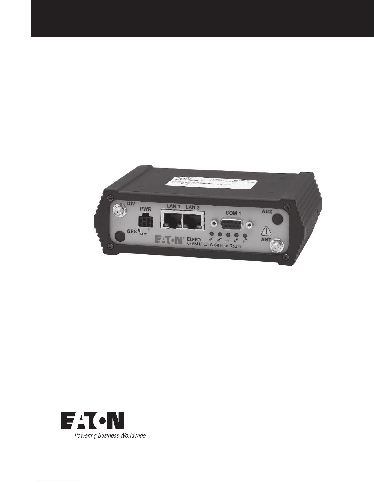
The ELPRO 645M™ Router from Eaton – simple, reliable
wireless connectivity without limitations. LTE with fallback
to 3G and 2G 3GPP technologies (VG-LAT models) and LTE
with fallback to 3G EVDO and 2G 1xRTT 3GPP2 technologies
(VG-LVZ models).
This single, flexible platform addresses a variety of wireless
communications needs with serial to IP conversion, over-the-air
configuration and system monitoring for optimal connectivity.
This ready to deploy broadband router enables wireless data
connectivity for up to two LAN and one serial device over public
cellular networks at 4G speeds.
Equipped for a broad range of fixed applications, 645M
router provides reliable connectivity for Programmable Logic
Controllers (PLCs), Remote Terminal Units (RTUs), Ethernet
web cameras or any other Ethernet or serial device. For mobile
applications, this intelligent broadband router incorporates an
optional highly-sensitive 56-channel GPS receiver, GLONASS
capable and an intelligent algorithm that offers outstanding
receive sensitivity and improved accuracy, integrity and
availability of GPS signals. An optional, built-in Wi-Fi access
point also allows your tethered devices to remain connected
even when you leave the vehicle.
This widely deployed wireless solution delivers countless
software capabilities. OEMs may tailor the 645M router by
loading their application on the Open Developer Platform (ODP)
which allows a Linux application to run on a partition of the
embedded flash memory.
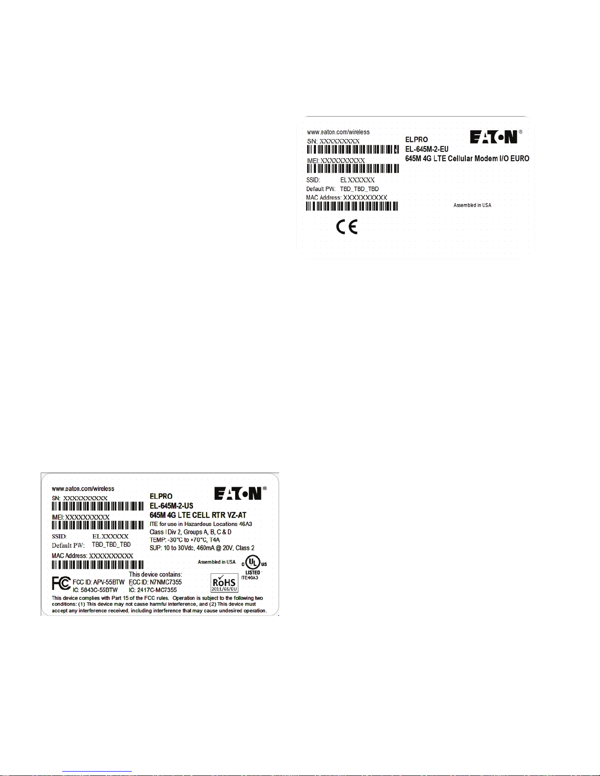
1.1 Model identification
The model identification label can be found on the bottom of
your 645M router. This label contains the product part number,
the serial number, FCC and IC IDs as well as carrier-specific
information that will be required when activating your
data account.
Figure 1. Verizon/AT&T LTE model identification label
Figure 2. International LTE model identification label
1.2 Features and benefits of the 645m broadband
4G LTE cellular router
•
4G/LTE cellular connectivity with fallback support to 3G and
2G connectivity
•
Supports dynamic or static IP
•
Inbound and outbound Ethernet routing
•
DHCP server and Inbound port mapping/translation
(Port Forwarding)
•
Firewall configuration for increased network security
•
Diversity antenna port for increased receive sensitivity
•
Local or remote configuration using HTTPS secure
web server
•
TCP/IP packet assembler and disassembler for serial
connected devices
•
Inbound IP termination with static IP
•
Modem domain names with dynamic DNS
•
Embedded Linux on Cortex-A9 processor
•
Internet access and web browsing via Ethernet connector
•
VPN support
•
RADIUS authentication for webpage access
•
On board 1.8/3V SIM socket
•
Analog and Digital I/O – 4 Analog inputs, 7 Digital inputs and
7 Digital outputs
•
Remote Management for router firmware, radio firmware,
and configuration
•
SNMP support
1 645M 4G/LTE CELLULAR ROUTER MN032003EN March 2017 www.eaton.com

1.3 General specifications
Product specifications are subject to change without notice.
1 Product overview
Interface Connectors RS-232 / RS-485 DE-9S Connector (DCE female)
Power Connector Molex 43045-4000 MicroFit 3.0, 4 pin header with Ignition Sense input
LED Indicators RSSI, SVC, NET, GPS, AUX
Antenna Interface Primar y Antenna 50-ohm SMA Female
Size 4.5 (L) x 6.0 (W) x 1.9(H) inches (11.4 x 15.2 x 4.8 cm)
Weight 1.94lb (0.88 kg)
Power Input 9-32 VDC
Maximum TX Power LTE 23 dBm
Rx Sensitivity LTE >-99 dBm
615M-1-US LTE / HSPA MODE
10/100 Base-T Full Duplex (Dual)
22 Pin I/O Port
Mini USB Service port — provided for convenience when upgrading cell module only.
Diversity Antenna 50-ohm SMA Female
CDMA 24 dBm
CDMA >-110 dBm
LTE CAT 3
Band 2 (1900 MHz) TX: 1850-1910 MHz; Rx: 1930-1990 MHz
Band 4 (AWS) (1700/2100 MHz) T X: 1710 – 1755 MHz; Rx: 2110 – 2155 MHz
Band 5 (850 MHz) TX: 824 – 849 MHz; Rx: 869 –894 MHz
Band 17 (70 0 MHz) T X: 704 – 716 MHz; Rx: 734 –746 MHz
Band 25 (190 0 MHz G Block) TX: 1850 – 1915 MHz; Rx: 1930 – 1995 MHz
UMTS/HSPA
Band 1 (2100 MHz) T X: 1920 - 1980 MHz; Rx: 2110 – 2170 MHz
Band 2 (1900 MHz) TX: 1850-1910 MHz; Rx: 1930-1990 MHz
Band 4 (AWS) (1700/2100 MHz) T X: 1710 – 1755 MHz; Rx: 2110 – 2155 MHz
Band 5 (850 MHz) TX: 824 – 849 MHz; Rx: 869 –894 MHz
Band 8 (900 MHz) TX: 880 - 915 MHz; Rx: 925 – 960 MHz
GSM/GPRS/EDGE
Band 2 (PCS 1900 MHz) TX: 1850-1910 MHz; Rx: 1930-1990 MHz
Band 3 (DCS 1800 MHz) TX: 1710 – 1785 MHz; Rx: 1805– 1880 MHz
Band 5 (GSM 850 MHz) TX : 824 – 849 MHz; Rx: 8 69 –894 MHz
Band 8 (EGSM 900 MHz) T X: 880 - 915 MHz; Rx: 925 – 960 MHz
615M-1-EU LTE CAT 3
Band 3 TX: 1710 – 1785 MHz; Rx: 1805 – 1880 MHz
Band 7 TX 2500- 2570 MHz; RX 2620 - 2690
Band 8 TX: 880 - 915 MHz; Rx: 925 – 960 MHz
Band 20 TX: 832 - 862 MHz; Rx: 791 – 821 MHz
UMTS/HSPA
Band 1 (2100 MHz) T X: 1920 - 1980 MHz; Rx: 2110 – 2170 MHz
Band 3 TX: 1710 – 1785 MHz; Rx: 1805 – 1880 MHz
Band 8 TX: 880 - 915 MHz; Rx: 925 – 960 MHz
GSM/GPRS/EDGE
Band 3 (1800 MHz) T X: 1710 – 1785 MHz; Rx: 1805 – 1880 MHz
Band 8 (900 MHz) TX: 880 - 915 MHz; Rx: 925 – 960 MHz
Temperature Operating: -30°C to +70°C 100% duty cycle. Note: Cellular T X power may be reduced outside this range;
Storage: -40° to +85°C (-40° to +185°F)
Emissions FCC Part 15b
Transport Protocols UDP/TCP
Command Protocol Web Interface
2645M 4G/LTE CELLULAR ROUTER MN032003EN March 2017 www.eaton.com
1 Product overview
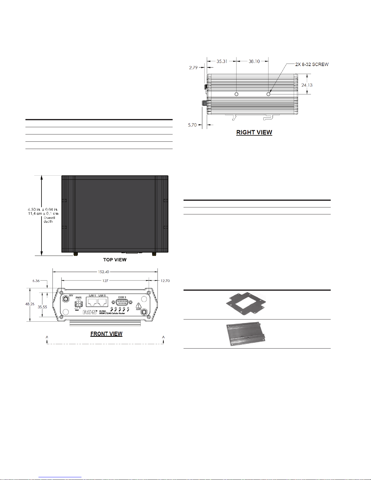
1.4 Mechanical specifications
The following table and figure show overall dimensions of the
645M router. Dimensioned drawings of units with mounting
brackets are provided in Appendix B. The drawings and
associated data may be used for layout reference, but it is
advised that a physical comparison be made to the modem and
bracket before laying out and drilling mounting holes.
Table 1. Overall dimensions, ELPRO 645M models
Dimension Inches Centimeters
Height 1.9 0 4,83
Width 6.00 15,2
Depth 4.50 ± 0.04 11,4 ± 0,1
Depth (Chassis only) 4.28 10,9
Figure 3. ELPRO 645M standard and mobile overall
dimensions. Same mounting holes (not shown) and
dimension on bottom of Chassis
#8-32 UNC – 2B thread × 0.30 in. (0,76 cm) depth
2 holes for mounting both sides (4 holes total).
1.5 Order information
The following table shows the available order options and part
numbers required for ordering 645M routers.
Table 2. 645M Order Information
Router Model Part Number
615M-1 LTE North America 615M-1-US
615M-1 LTE Rest of world 615M-1-EU
1.5.1 Mounting brackets
A mounting bracket is provided with each ELPRO 615M.
•
For fixed-location applications, a flat-plate bracket provides for
low-profile, space-saving mounting
•
For applications requiring mounting to a DIN rail, the included
bracket can be used
Table 3. 645M mounting brackets
Application Bracket
Panel BR-6 15M -PL ATE
Din Rail (included
with modem)
Four screws are provided with each bracket to fasten the
bracket to the body of the 645M router.
•
DIN Rail – Four #6-32 × ¼ (3/16-inch thread length)
clear-zinc plated stainless steel Philips undercut flat head
(82° countersink) screws are provided to fasten the
flat-plate mounting bracket to the 645M chassis
•
Flat Plate – Four #6-32 × ¼ (3/16-inch thread length)
clear-zinc plated stainless steel Philips undercut flat head
(82° countersink) screws are provided to fasten the flat-plate
mounting bracket to the 645M chassis
Part number /
description
Flat plate
(fastens to the top or
bottom of the chassis)
BR-615M-DINCLIP
DIN Rail Mounting
Assembly
(fastens to the top or
bottom of the chassis)
3 645M 4G/LTE CELLULAR ROUTER MN032003EN March 2017 www.eaton.com
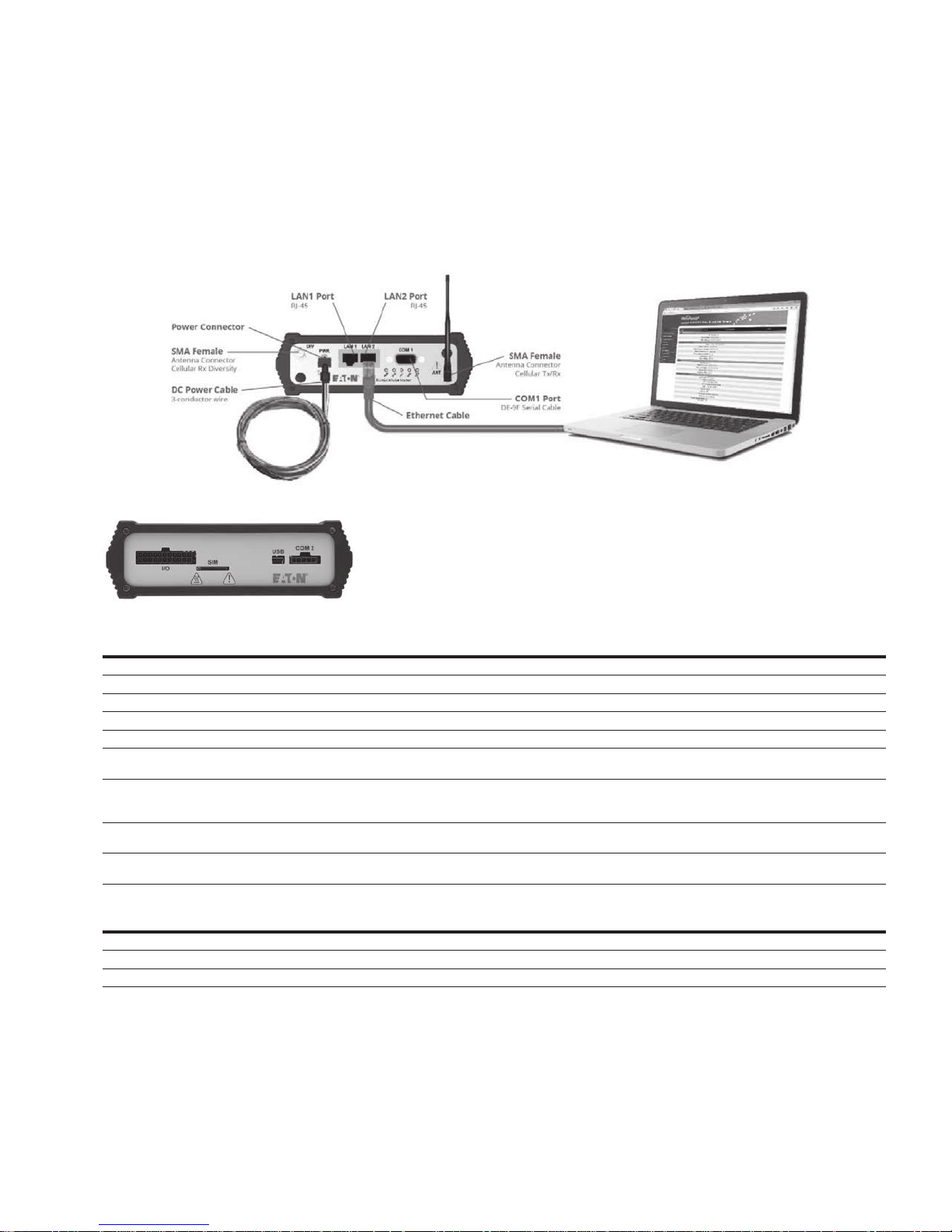
1.6 External connectors
This section describes the external connectors for the
645M router.
•
Figure 4 shows the front panel connections
•
Figure 5 shows the rear panel
Figure 4. Front panel – standard fixed models
Figure 5. Rear panel connections
1 Product overview
Table 4. External connectors
Panel indicators Connection Description
COM 1 RS-232 / RS-485 Serial to IP conversion use
ANT SMA Primar y RF Antenna
DIV SMA Cellular Diversity Antenna
LAN 1, LAN 2 RJ-45 Interface for Ethernet connection to devices
USB USB Mini Available for diagnostic use.
RESET Depress switch to reset router. Press and hold during boot to revert settings to
PWR Jack Molex 43025-0 400 receptacle for four-pin power plug with
optional ignition sense
SIM SIM Card socket Interface for SIM card (Mini-SIM “2FF” form factor). Your wireless service
COM 2 Molex 43650-0501 receptacle for 5-pin RS-232 TTL adapter
5-Pin TTL Serial Port
factory defaults.
Bottom pins: +9-32VDC power (pin 1) and ground (pin 2)
Top pins: optional ignition-sense (3) and not connected (4).
See diagram for compatible cable on the following page.
provider will supply the SIM card with your wireless service contract.
Available for diagnostic use. Serial port – Level conversion cable required.
Table 5. Status LEDs
Function Off Green Flash green Red Flash red Amber Flash amber
RSSI Strong Weak/None Medium
SVC 3G/4G 3G/4G/NC NC 2G 2G/NC
NET No connectivity Rx data Tx data Rx / Tx
•
If SVC is solid, then the modem is connected to the cellular
network. If it is flashing, the modem is trying to connect
to the network
The behavior of the LEDs is different than the table at boot. The
boot sequence is: all red, all off, all amber, all green, all flash
green three times, and then the boot sequence is complete.
4645M 4G/LTE CELLULAR ROUTER MN032003EN March 2017 www.eaton.com
1 Product overview
1.7 Antenna
Primary cellular antenna connections are SMA female
connectors and must be used with antenna with SMA
male connectors. When using a direct mount or rubber
duck antenna, choose the antenna specific to your band
requirements. Mounting options and cable lengths are
user’s choice and application specific.
The diversity antenna connector, labeled DIV, can be used
for a Diversity antenna. The diversity port supports all bands.
Connect a dual band cellular antenna to this port to implement
RX diversity on the unit and increase receive sensitivity on the
cellular network.
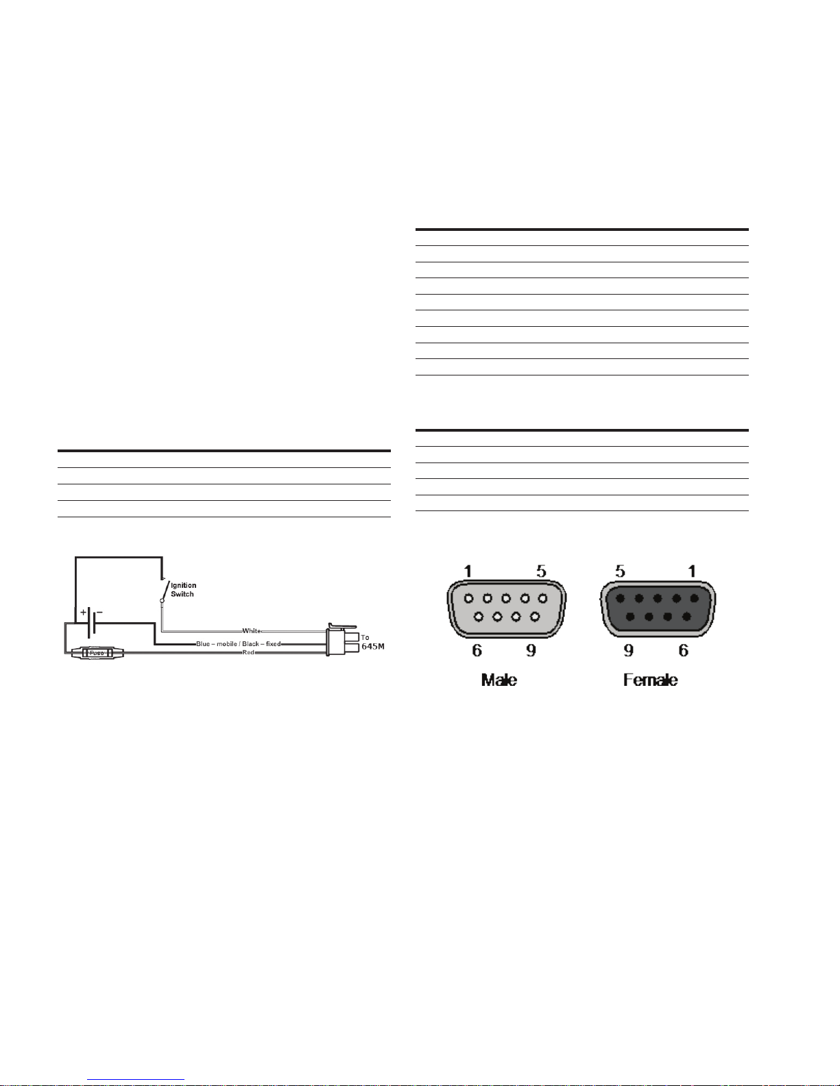
1.8 Power cable pinout
The Eaton 645M ships with a 6 foot DC three-wire power
cable that does not contain a fuse. AC power adapter or power
supplies are available as an optional accessory.
When the Ignition-sense line is not required, the ignition sense
line (white wire) should be shorted to VIN / VBatt (red wire).
Table 6. Power cable pin-out, signal, and wire colors
Pin Signal Color fixed
1 VIN / VBatt = 9 – 32V DC Red
2 Ground Black
3 Ignition Sense White
4 No Connect NA
Figure 6. Wiring for Ignition sense
1.9 RS-232 / RS-485 serial port
Table 8 provides the serial cable design information to integrate
the 645M modem into your system. Table 9 gives the default
RS-232 / RS-485 communication parameters.
Table 7. Standard RS-232 / RS-485 DE-9 pinout
Pin RS-232 Signal RS-485 Signal Direction
1 DCD – <–(Out)
2 RXD RXP <–(Out)
3 TXD TXP –>(In)
4 DTR – –> (In)
5 GND –
6 DSR – <–(Out)
7 RTS TXN –>(In)
8 CTS RXN <–(Out)
9 3 .3-12V * 5V <–(Out)
*Power adjustable in GUI; used to power attached adapters
Table 8. Default RS-232 / RS-485 communication parameters
Parameter Valu e
Bits Per Second 115,20 0
Data Bits 8
Parity None
Stop Bits 1
Flow Control None
Figure 7. DE-9 Connectors
The fuse provided inside the fuse-holder that is part of the
wiring for mobile applications is a 2 Amp fast-acting
fuse (EF2AL250VP).
5 645M 4G/LTE CELLULAR ROUTER MN032003EN March 2017 www.eaton.com
1.10 RESET button
The RESET button can be used to return the 645M to its
factory default settings. Power-on the unit then promptly
press-and-hold the RESET button. The LEDS will cycle through
all red, all off, all amber, all green. During the all green phase,
the RSSI LED will turn red to show that the configuration is
being reset to defaults. Once the LEDs flash all green 3 times,
release the RESET button and proceed as normal.
2 Getting started
2.1 Package contents
•
645M Router
•
Power Cable
•
22 Pin I/O Cable
•
Mounting bracket
•
Quick-Start Guide
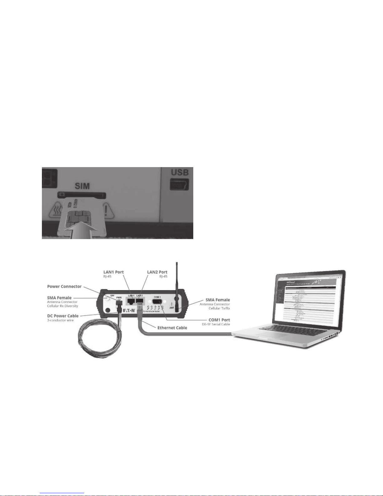
2.2 Device connections
1. Insert the SIM card into the spring-loaded SIM slot
as shown
Figure 8. Insert SIM card into SIM slot
2 Getting started
2. Connect a cellular antenna (for Tx/Rx) to the female SMA
connector labeled ANT on the front of the 645M modem.
Optionally, a second cellular antenna may be connected
to the female SMA connector labeled DIV on the front
panel of the 645M modem for Rx diversity
ote:N Use of dual band cellular antennas is preferred.
3. Connect an Ethernet cable into a LAN port and plug the
other end into the network port of your PC
4. Connect the DC power cable (or optional AC power
adapter) to an applicable power source and plug the
connector into the modem power (PWR) connector. If
using the fused power cable to connect to a DC supply
(car battery), use the diagram in Figure 6: Wiring for
Ignition sense and accompanying pin-out information in
Table 6 to connect the unit
Figure 9. Connect antenna to ANT connector, connect Ethernet cable to either LAN port, and connect power cable
2.3 Lan configuration
The Eaton router is configured via a Web-browser interface and
contains a DHCP server which will automatically assign an IP
address to your computer, however in some cases it may be
necessary to change the network settings on your computer
to accept the IP address assigned by the 645M. Refer to your
operating system documentation for detailed network
setup instructions.
2.4 Cellular connections
Before you begin, you will need an active Cellular account with
the carrier of your choice.
6645M 4G/LTE CELLULAR ROUTER MN032003EN March 2017 www.eaton.com
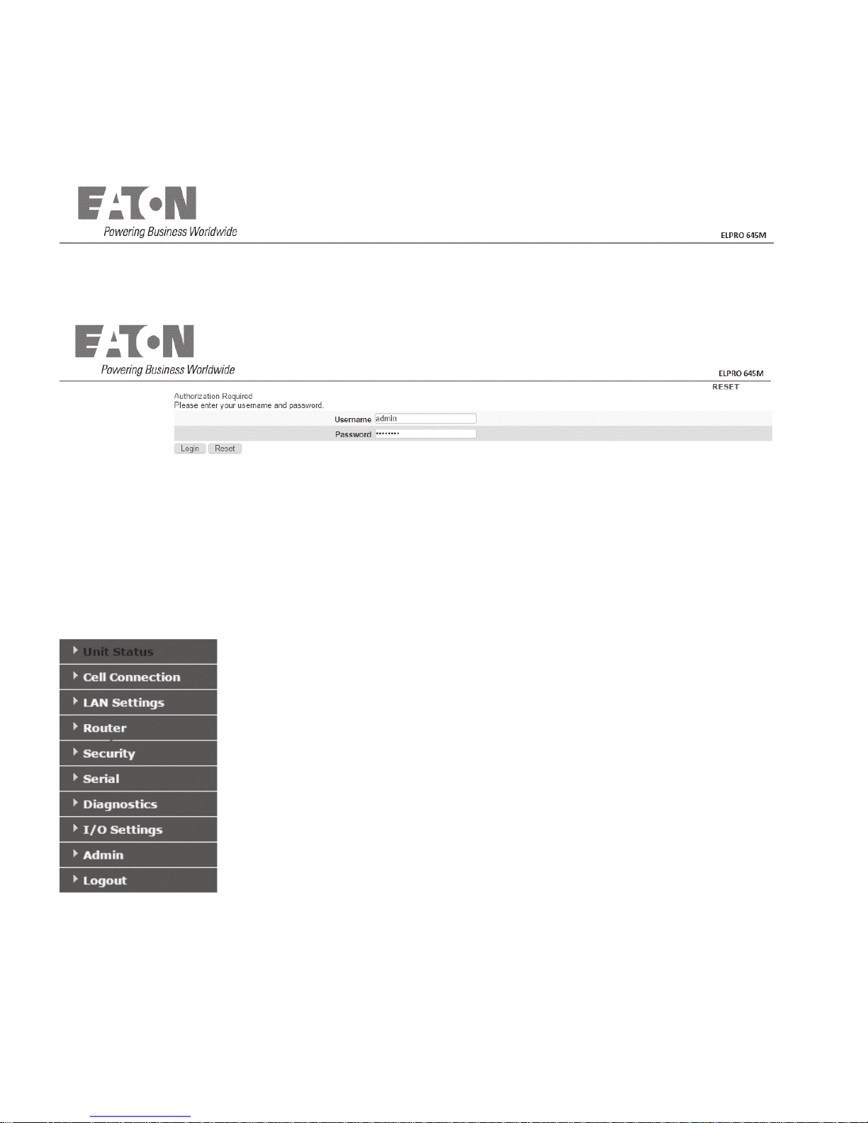
3 645M web interface
Figure 10. Eaton 645M cellular broadband router web interface banner
Start your Web browser and enter 192.168.1.50 in the
address bar. A Web Server Authentication window appears.
Figure 11. Web server authentication window
Enter the User Name: admin and the Password: password and
click OK to log into the modem’s Home Page. ELPRO 645M
Web interface is divided into two sections. On the left is the
main navigation pane (shown in the following figures). On the
right is the content area for the desired page (shown on the
following pages).
ote:N Eaton strongly recommends that the default password
be changed before the 645M is deployed on a public
cellular network.
Figure 12. Main navigation pane – fixed
Save & apply and save
On each screen, you have the option to Save & Apply or Save
your configuration changes. Save & Apply commits the changes
to persistent configuration files. Save only stores the changes
in volatile storage, and changes can be reverted back to the
original configuration settings by clicking the Unsaved Changes
link at the top of the page and the Revert button. You can also
modify the configuration values in more than one page and
commit all the changes with the Unsaved Changes’ Save &
Apply button.
3.1 Unit status
The Unit Status is the first page displayed when navigating to
the ELPRO 645M Web interface and is the home page. Select
Unit Status from the left navigation pane to return to this page.
From this page you can view Status, System information or
access Basic Settings.
3.1.1 Status
The Unit Status page displays connection information.
This screen refreshes automatically every five seconds.
You can disable the automatic refresh by clicking the Auto
Refresh button.
ote:N If the computer you are using has previously been
used to set up another Eaton router at that same IP
address, you may need to delete browser history
(specifically, Temporary Internet files) for the pages
of the web interface to display correctly.
7 645M 4G/LTE CELLULAR ROUTER MN032003EN March 2017 www.eaton.com
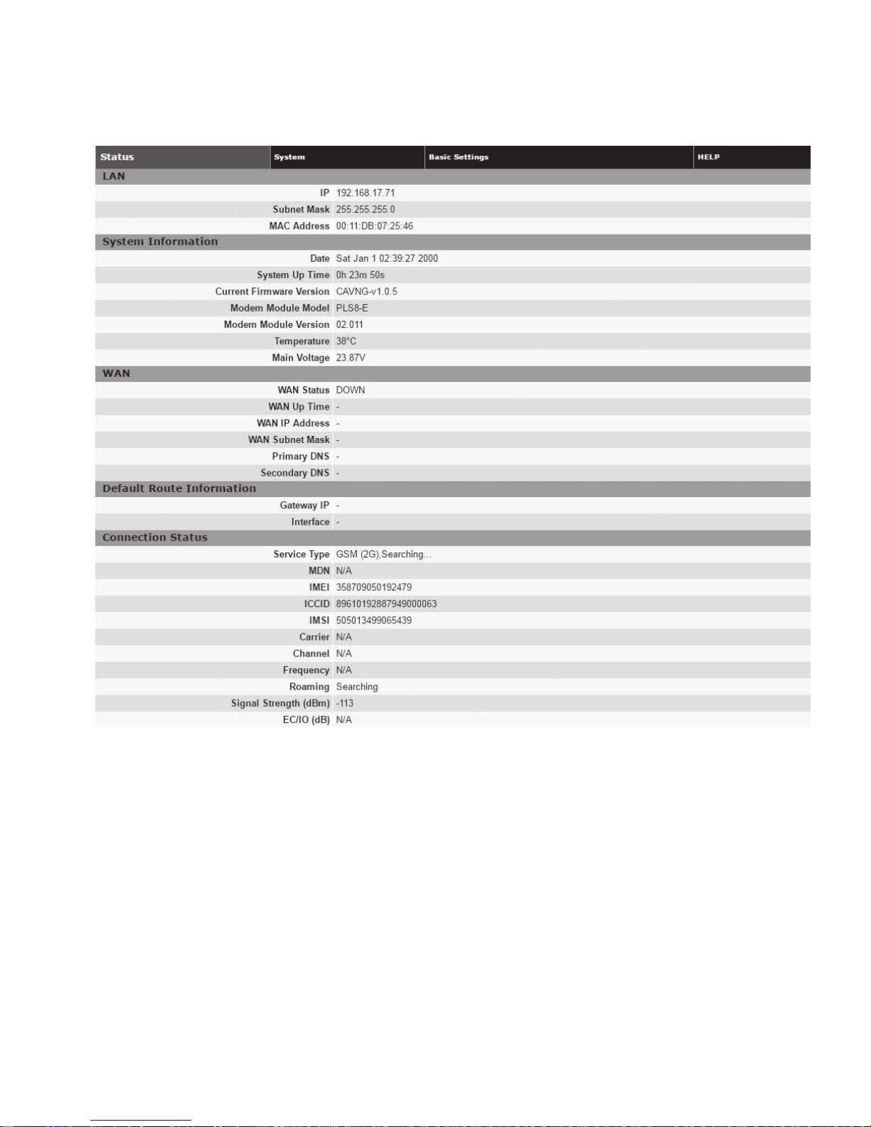
Figure 13. ELPRO 645M unit status tab
3 645M web interface
LAN
•
IP
LAN IP address of this device (the modem)
•
Subnet mask
LAN subnet mask for the modem
•
MAC address
Media Access Control Address. Every Ethernet device (i.e.
LAN cards) has a unique hardware serial number or MAC
address to identify each Network Device from all others
System information
•
Date
Current date and time (UTC) received from the GPS receiver
(Mobile models) or from a time server (see Basic Settings »
Network Time).
•
System up time
Uptime in hours, minutes, and seconds
•
Current firmware version
Firmware version currently loaded. Please contact Eaton
technical support for the latest updates
•
Modem module model
Model of the cellular modem installed
•
Modem module version
Displays the firmware version of the modem. This may vary
depending on the vendor of the radio inside the modem
•
Temperature
Current internal temperature of the ELPRO 645M
•
Main voltage
System input voltage sensed by the modem
8645M 4G/LTE CELLULAR ROUTER MN032003EN March 2017 www.eaton.com

3 645M web interface
WAN
•
WAN status
Status of the cellular connection, usually UP when
connected properly
•
WAN IP address
IP address of the 645M, as assigned by the cellular carrier,
when WAN is UP
•
WAN subnet mask
Subnet Mask of the 645M, as assigned by the cellular carrier,
when WAN is UP
•
Primary DNS
The Primary DNS server, as assigned by the cellular carrier,
when WAN is UP
•
Secondary DNS
The Secondary DNS server, as assigned by the cellular
carrier, when WAN is UP
Default route information
•
Gateway IP
The IP address of the gateway on the cellular network, if
provided by the carrier, or the gateway on the Wi-Fi network,
if Wi-Fi Client mode is enabled and a Wi-Fi connection
is active
•
Interface
The interface (WAN or WI-FI) used to reach the
Gateway IP
Connection status
The information displayed in this section will vary
depending on the Service Type. The possible options are
described below.
•
Service type
Determines the type of network your device has
connected to: GPRS, EDGE, HSDPA, HSUPA, HSPA or LTE.
“Searching...” will display if the SIM is invalid, missing, or if
you need to enter the PIN
•
MDN
(Mobile Directory Number) The actual phone number of
the device as supplied by the carrier. When the unit is
successfully provisioned, the phone number for the user
account will be displayed. The MDN may display “NOT
AVAILABLE” if the PIN status is disabled or the MDN
is unknown
•
IMEI
The International Mobile Equipment Identity is a unique
15-digit number that serves as the serial number of the
cellular module in the modem
•
ICCID
The Integrated Circuit Card Identifier is the primary account
number stored in the SIM
•
IMSI
The International Mobile Subscriber Identity is a unique
number which designates the subscriber. This number is
used for provisioning in network elements. The IMSI may
display “NOT AVAILABLE” if a SIM card is not detected
•
Carrier
Cellular provider name or code. “No SIM or PIN Required”
is displayed if the SIM is invalid missing, or if the correct PIN
has not yet been entered
•
Channel
Cell Site channel number at which the modem is connected
and is useful for the carrier in the event of troubleshooting
•
Roaming
Displays Roaming or Not Roaming
•
Signal strength
Measured in dBm, this is the Received Signal Strength
Indication (RSSI)
•
EC/IO
(Displayed depending on model and Service Type) Measured
in dB, EC/IO is a measure of interference. Values closer to 0
indicate weaker interference
•
RSRQ
(Displayed depending on model and Service Type) Measured
in dB, RSRQ is a measure of both interference and signal
with adjacent towers. Values closer to 0 indicate better
signal quality
9 645M 4G/LTE CELLULAR ROUTER MN032003EN March 2017 www.eaton.com
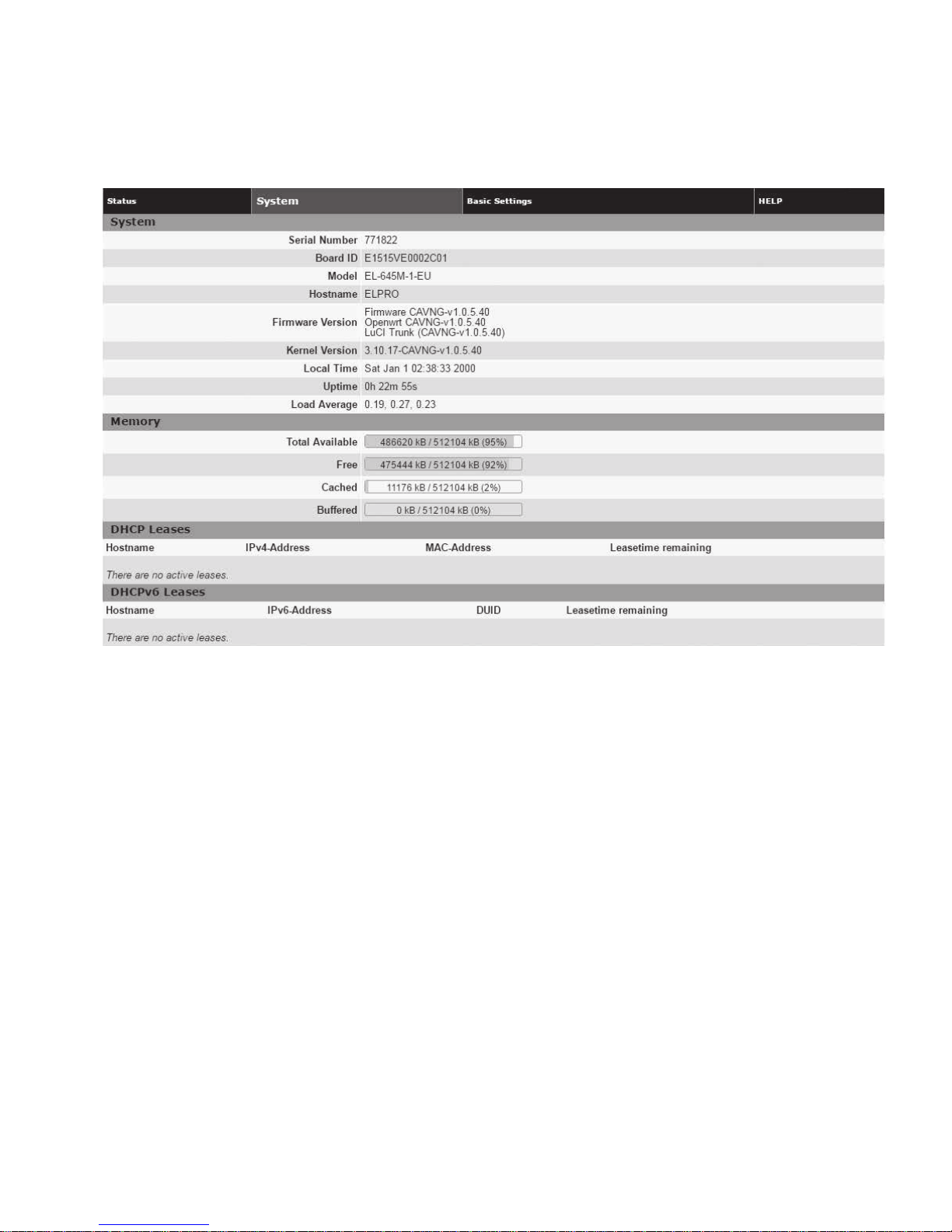
3.1.2 System
Figure 14. Unit status — system
3 645M web interface
System
•
Serial number
The router serial number is a unique ID assigned when the
product was built
•
Board ID
Unit motherboard identifier
•
Model number
Unit model number defining its capabilities and features
•
Hostname
The name of the router provided by the operating system
•
Firmware version
The version of the top-level component firmware packages in
the router OS
•
Kernel version
The version of the Linux kernel in the router OS
•
Local time
The current system time observed by the router. Source
may be from the configured NTP server or the GPS receiver,
if installed
•
Uptime
The time since the router was last rebooted
•
Load average
The average number of processes in a runnable or
non-interruptible state for the past 1, 5, and 15 minutes
Memory
•
The current memory usage, broken out into Total Available,
Free, Cached and Buffered categories
DHCPv6 Leases
•
The list of IPv4 and IPv6 leases given out to clients on the
wired or wireless LAN interfaces by the DHCP server
Associated stations
Currently bounded Access Point information.
•
MAC-address
MAC-addresses of clients which are connected
•
Network
SSIDs of clients which are connected.
•
Signal
Signal strength of AP
•
Noise
The noise level indicates the amount of background noise in
the environment
•
RX rate
Rx Rate is the rate at which packets are received
from router
•
TX rate
Tx Rate is the rate at which packets are sent from router
10645M 4G/LTE CELLULAR ROUTER MN032003EN March 2017 www.eaton.com
3 645M web interface
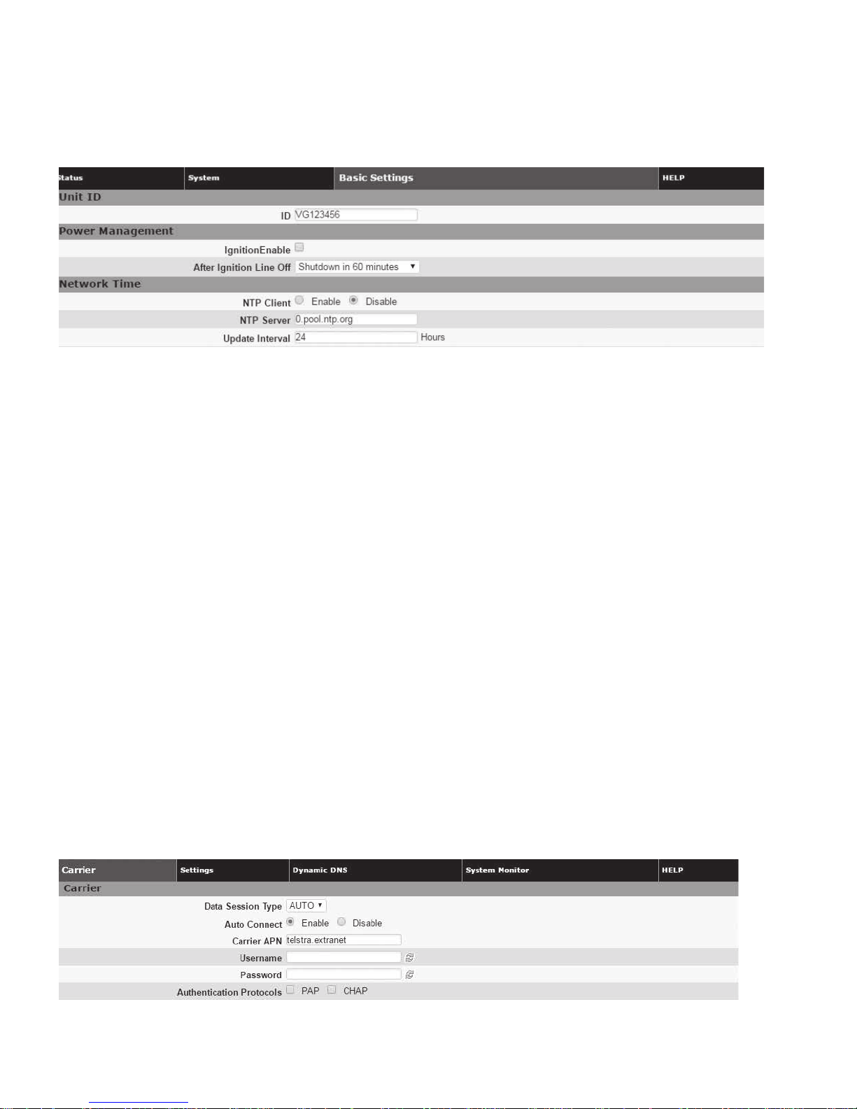
3.1.3 Basic settings
Figure 15. Unit status — basic settings
Unit ID
•
ID
The identification string serves to distinguish this unit. It is
also the TAIP identification for GPS reporting and serves as
the syslocation for the SNMP facility. Unit ID can be up to
32 characters long and can consist of letters, digits and the
underscore ‘_’ character.
Power management
Depending on power cabling, the ELPRO 645M may stay ON
regardless of whether the vehicle ignition is on. The unit can be
configured to automatically shut down 1, 5, 30, 60, 120 or 240
minutes after ignition has been turned off. Leaving the unit live
allows the driver to use the modem without idling the vehicle
and defining a shut-off time limit prevents the modem from
draining the battery when the vehicle is unoccupied.
•
Ignition Enable
Disabled by default
•
After ignition line off
Select a time limit: 1, 5, 30, 60, 120, or 240 minutes
3.2 Cell connection
Select Cell Connection from the left navigation pane to access
the Carrier, Settings, Dynamic DNS and System Monitor tabs.
3.2.1 Carrier
The Carrier tab enables you to configure the carrier (cellular
provider) and credentials to be used for data calls.
Network time
The ELPRO 645M is capable of maintaining the current time
(UTC) by synchronizing itself with a Network Time Protocol
(NTP) Server. You may specify a server domain name or IP
address and how frequently the router should synchronize with
the server. The router must have DNS access and a route to the
internet to synchronize with the supplied default ntp.org
server – this is not always true on private cellular networks.
The router does not save or track time while powered off, so
time will be inaccurate until the router can connect with the
server, which it does on startup (in addition to synchronizing
according the Update Frequency specified).
•
NTP client
Disabled by default. Select Enable to activate the router’s
NTP client to synchronize with the specified server
•
NTP server
Enter the domain name or IP address of the desired NTP
Server. Most public NTP Servers have a posted usage policy.
A review of usage policies and the choice of an appropriate
server is recommended
•
Update interval
Specify the frequency to synchronize the router time with
the configured NTP Server. By default, synchronization is
set 24 hours
Figure 16. Cell connection — carrier
11 645M 4G/LTE CELLULAR ROUTER MN032003EN March 2017 www.eaton.com
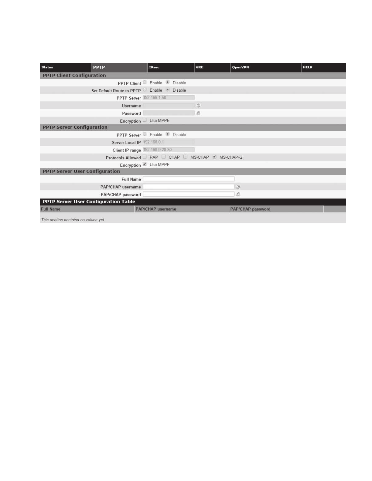
Figure 17. For Multicarrier cell connection - carrier
3 645M web interface
ote:N For multicarrier: Carrier change will require a SIM card
change, will reboot the device and will take approx
three (3) minutes to apply.
Carrier
•
Carrier (645M-1-US only)
Select Verizon or AT&T. NOTE: On a carrier change, the
645M will reboot and take approximately 3 minutes to
update the cell module
•
Data session type
Select Auto, 4G, 3G or 2G.
•
Auto connect
Select Enable (the default and recommended setting), and
the modem will automatically dial the connection at startup,
and to attempt reconnection if the connection is lost. Select
Disable to prevent the modem from automatically connecting
at startup. When disabled, a button will be displayed that
can be used to manually connect or disconnect the wireless
WAN service.
If Auto Connect is enabled and the modem fails to connect,
the unit will attempt to reconnect two times and then make an
attempt at one minute, at two minutes, at eight minutes, and
then every fifteen minutes until successful.
•
Carrier APN
The Access Point Name required by the cellular provider to
access the network. This value may determine if the router
receives a publicly routable WAN address. Enter the APN
provided by the carrier.
•
Username
Username required by the cellular provider. Leave blank if
not required.
•
Password
Password required by the cellular provider. Leave blank if
not required.
•
Authentication protocols
Configure the authentication protocol to be used, or none.
If no protocol is selected (the default and recommended
setting for most applications), the ELPRO 645M will try to
negotiate a protocol with a cell tower, if the cellular carrier
allows negotiation. If a protocol is selected, then the router
will only accept requests for the specified protocol(s), where
PAP is Password Authentication Protocol and CHAP is
Challenge-Handshake Authentication Protocol.
• PAP: The Password Authentication Protocol is a pre-shared
key method for authenticating with the cellular provider.
• CHAP: The Challenge-Handshake Authentication Protocol
is a two-way authentication scheme between router
and provider.
ote:N Normally the cell provider does not require a username
or password, in which case leave the User and
Password fields blank. SIMs from some carriers
for special applications may require user name and
password to establish WAN connection with the
Cellular network.
12645M 4G/LTE CELLULAR ROUTER MN032003EN March 2017 www.eaton.com
3 645M web interface
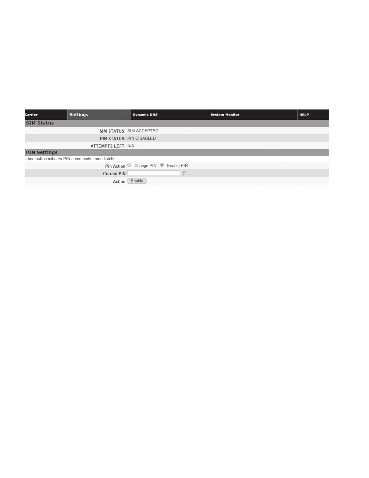
3.2.2 Settings
The carrier settings displayed on this page differ depending
on which carrier is being used at the time.
One of the key features of LTE is the Subscriber Identity
Module (SIM), commonly known as SIM card. The SIM is
a detachable smart card containing the user’s subscription
Figure 18. Cell connection — settings
information. This allows the user to retain his or her
information when switching handsets or wireless devices,
independent of which handset or wireless device they are
using. The SIM has a security feature which, when enabled,
requires the user to enter a valid PIN before the modem will
connect to the cellular network.
SIM status
The Current Status section displays the current status of the
SIM (whether a SIM card is present, and if so whether it
is valid) and PIN (whether a PIN has been entered and PIN
security enabled).
•
SIM status (status text)
SIM ACCEPTED displays when a valid SIM card is inserted
properly in the modem. NO SIM displays if the SIM card is
invalid, missing, or installed incorrectly
•
PIN status (status text)
PIN DISABLED displays when PIN security is not enabled.
PIN ENABLED displays when PIN security is enabled.
PIN ACCEPTED displays when PIN security is enabled and
a valid PIN is entered
•
Attempts left
Indicates the number of attempts remaining to correctly
enter the PIN before the SIM is locked. Maximum number
of attempts is three. If SIM is locked, you must contact your
cellular carrier to unlock
PIN settings
The Pin Settings section enables you to enter a PIN, change
a pin, enable PIN security or disable it. Instructions for the
available actions and associated options displayed in this
section of the Web page change depending on the SIM status,
whether a PIN has been entered, and whether PIN security is
enabled or disabled.
The default setting for PIN security is disabled and you will see
the status message “Action: PIN is disabled. To change it, it
must be enabled first.”
ote:N Before enabling PIN security, make sure you have the
PIN provided by your wireless carrier.
To enter the PIN provided by your wireless carrier
(for a new modem)
Change Enable PIN from No to Ye s , enter your carrier-provided
PIN into the Current PIN field, and click Save to access the PIN
security settings.
To change your PIN or change PIN security settings
(enable or disable PIN security, change whether PIN is
remembered, or change your PIN)
Change PIN from Yes to No, enter your PIN into the Current
PIN field, and click Save to access the PIN security settings.
To change the PIN status
Once the PIN has been entered successfully, the status
message displays “Action: You may change only one of the
following three options at a time,” and three options
are presented.
•
Remember PIN (Enter Current PIN) Yes / No
• To have your PIN remembered (not need to be entered
each time to establish connection), select Ye s
• To not enable this feature (not have your PIN
remembered), select No
• Enter your PIN in the Current PIN field and click Save to
make your selection take effect
•
Disable PIN (Enter Current PIN) Yes / No
• To disable PIN security, select Yes
• To enable PIN security, select No
• Enter your PIN in the Current PIN field and click Save to
make your selection take effect
•
Change PIN (Enter Current PIN, New PIN and Confirm
PIN) Yes / No
• To change your PIN, select Ye s . Enter your PIN in the
Current PIN field, enter your new PIN in the New PIN
field, and enter your new PIN again in the Confirm New
PIN field. (The PIN you enter in the New PIN and Confirm
New PIN fields must match exactly.)
13 645M 4G/LTE CELLULAR ROUTER MN032003EN March 2017 www.eaton.com
3 645M web interface
ote:N If you enter too many or too few characters, or
characters that are not allowed in a PIN, rules for valid
PIN length and character selection are displayed.
• To not change your PIN, select No
• Click Save to make your selection take effect
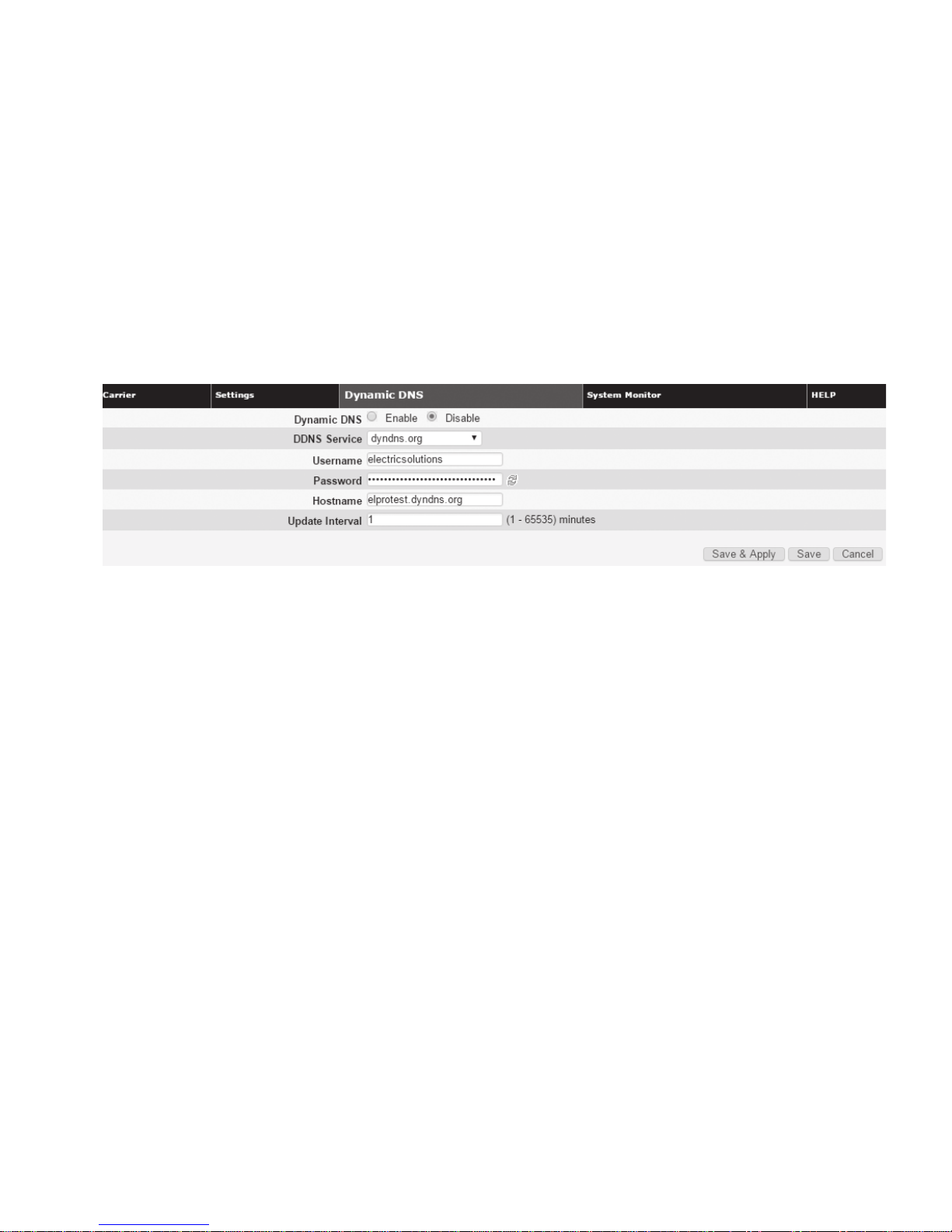
3.2.3 Dynamic DNS
Dynamic DNS is a system which allows the domain name data
of a computer with a varying (dynamic) IP addresses held in
a name server to be updated in real time in order to make it
possible to establish connections to that machine without the
need to track the actual IP address themselves at all times.
Figure 19. Cell connection — dynamic DNS
When you have made and saved your change successfully,
the PIN Status text changes accordingly, reflecting the change
you made.
A number of providers offer Dynamic DNS services (“DDNS”),
free or for a charge. For example, a free service provided by
NO-IP allows users to setup between one and five host names
on a domain name provided by NO-IP.
•
Dynamic DNS
Selecting Enable will allow the modem to provide the
selected service dynamic IP address information. Selecting
Disable will stop any IP information from being sent to the
selected service
•
DDNS service
The internet address to communicate the Dynamic DNS
information to. Default is ” – custom –“ which exposes the
Custom URL field
•
Custom URL
DDNS Services not in the dropdown list can often still be
supported by use of a custom URL specified by the service
provider. Keywords in [square brackets] are replaced by their
actual values
ote:N If the default Custom URL, which references NO-IP,
fails to update, try the URL:
http://[USERNAME]:[PASSWORD]@dynupdate.noip.com/
nic/update?hostname=[DOMAIN]&myip=[IP]
•
Username
The username used when setting up the account. Used to
login to the Dynamic DNS service
•
Password
The password associated with the username account
•
Hostname
The hostname identified to the Dynamic DNS service. For
example, test.myserver.com
•
Update interval
Sets the interval, in minutes (0 to 65,535), the modem will
update the Dynamic DNS server of its carrier assigned IP
address. It is recommended to set this interval as long as
necessary. Each update is considered a data call by the
cellular provider and could deplete low usage data
plan minutes
14645M 4G/LTE CELLULAR ROUTER MN032003EN March 2017 www.eaton.com
3 645M web interface
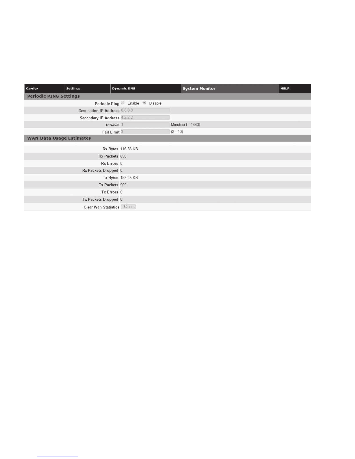
3.2.4 System monitor
The System Monitor tab allows access to the configuration of
additional self-monitoring for the modem to determine
Figure 20. Cell Connection — System Monitor
when service provider connections may have
been terminated.
Periodic PING settings
This section allows you to set up a periodic Ping test and
specify a failure limit above which the modem will reset.
•
Periodic ping Enable/Disable
Default setting is disabled
•
Destination IP address
User may enter an accessible IP address or domain name
that will respond to a ping command
•
Secondary IP address
User may enter an accessible IP address or domain name
that will respond to a ping command. This address will be
used if the entered number of consecutive ping failures
using the first address is reached
•
Interval
Time (in minutes) to wait between pings
•
Fail limit
Number of ping failures to accept before resetting the modem
WAN data usage statistics
This section tracks the data received from and transmitted to
the cellular network. This is a tool that may be used to estimate
network usage. These totals are tracked by the router. Your
carrier maintains separate statistics from which your billing
is determined. One way to use this tool is to track usage
over a fairly short period of typical usage. The total then can
be extrapolated to estimate longer time periods. This router
updates these statistics once approximately every 30 seconds.
Press the Clear button to reset the totals to 0.
•
Rx bytes
The total number of bytes received by the modem from the
cell network. All statistics will be cleared automatically if this
count exceeds 1 billion (1,000,000,000)
•
Rx packets
The total number of TCP and UDP packets received by the
modem from the cell network
•
Rx errors
The number of corrupted TCP and UDP packets received by
the modem from the cell network
•
Rx packets dropped
The number of TCP and UDP packets received by the
modem from the cell network that were not accepted. This
may occur due to memory or throughput problems
•
Tx bytes
The total number of bytes transmitted by the modem to the
cell network. All statistics will be cleared automatically if this
count exceeds 1 billion (1,000,000,000)
•
Tx packets
The total number of TCP and UDP packets transmitted by the
modem to the cell network
•
Tx errors
The number of corrupted TCP and UDP packets received by
the modem that were meant to be transmitted on the
cell network
•
Tx packets dropped
The number of TCP and UDP packets received by the
modem for transmit to the cell network that were not
accepted. This may occur due to memory or
throughput problems
Click Clear WAN Statistics to reset the totals to 0. These totals
are NOT cleared by a modem reboot.
15 645M 4G/LTE CELLULAR ROUTER MN032003EN March 2017 www.eaton.com
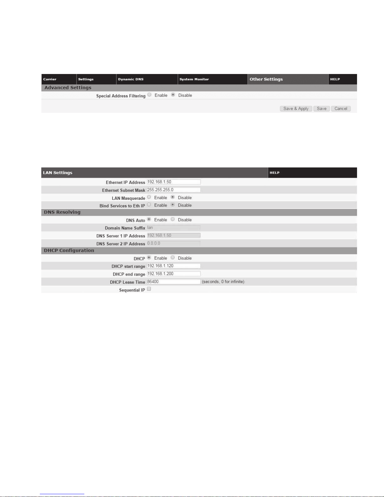
3.2.5 Other settings
Figure 21. Other settings
•
Special address filtering
Some traffic is not tolerated over the public internet.
This feature will add filters to prevent such traffic to go
out the interface. (the following destination IP addresses
3.2.6 Lan settings
Figure 22. LAN – LAN settings
3 645M web interface
will be discarded: 0.0.0.0/8, 192.0.0.0/24, 192.0.2.0/24,
198.51.100.0/24, 203.0.113.0/24, 192.168.0.0/16,
172.16.0.0/12, 10.0.0.0/8, 169.254.0.0/16, 224.0.0.0/4,
240.0.0.0/4).
LAN settings
•
Ethernet IP address
This sets the IP address of this device and is the address
used to access the configuration pages. If the IP address
changes you will have to re-enter the new IP address in your
browser to access the configuration pages. The default IP is
192.168.1.50
•
Ethernet subnet mask
Sets the subnet mask for the LAN side of the modem to
the device
Important: The LAN subnet must not overlap with the WLAN
subnet defined in the Access Point tab of the WLAN page.
•
LAN masquerade
When enabled, the 645M masquerades all Ethernet traffic
to the LAN, making all WAN traffic appear as if it originated
from the 645M. This can be useful in applications where
less-capable equipment on the local LAN cannot cope with
connections from multiple Host IP addresses
•
Bind services to Eth IP
UDP datagrams or TCP sockets from services inside the
645M (Serial, IO, GPS) normally appear to come from the
interface (LAN or WAN) closest to the destination. Enable
this option to force the source address to be the LAN
Ethernet IP address. This can be useful if packets are being
sent through a VPN tunnel. Note that outside of a tunnel,
NAT may still force the source address to be rewritten to the
WAN address
DNS resolving
•
DNS auto
Selecting Enable enables the 645M to act as DNS Proxy for
the DHCP clients. Selecting Disable will provide the DNS
Server 1 or 2 addresses to DHCP clients
•
Domain name suffix
Suffix to append to short, unqualified computer names for
local DNS lookup
•
DNS server 1 IP address
The Ethernet IP address of the preferred DNS server.
The default address is 192.168.1.50, the same as the LAN
Ethernet IP Address for the modem. If the LAN Ethernet
ID Address changes, the DNS Server 1 address will
automatically change to the same
•
DNS server 2 IP address
Ethernet address of the alternate DNS server. The default is
set to 0.0.0.0
16645M 4G/LTE CELLULAR ROUTER MN032003EN March 2017 www.eaton.com
 Loading...