

Eaton Cooper Power Series, 600 A 35 kV class BT-TAP, 600 A 35 kV class BOL-T, 600 A 15 kV class BT-TAP, 600 A 25 kV class BT-TAP Installation Instructions Manual
COOPER POWER
SERIES
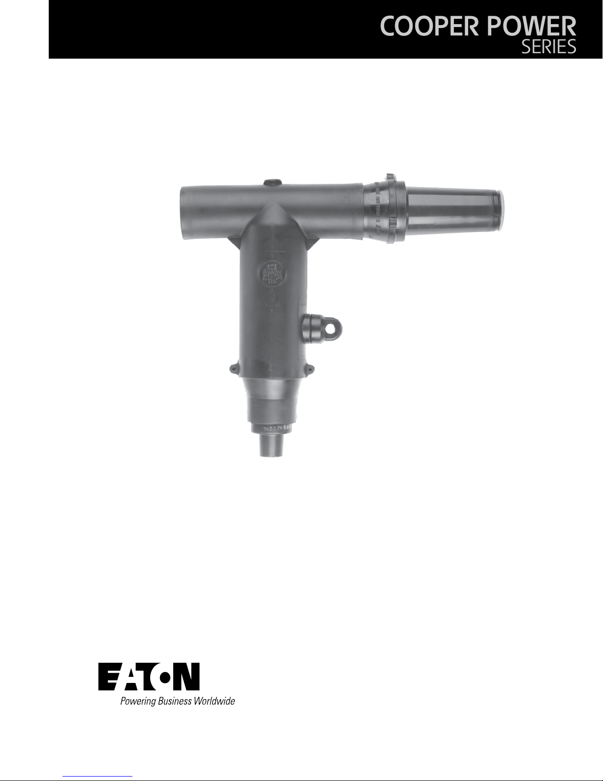
Deadbreak Apparatus
Connectors
MN650003EN
Effective February 2015
Supersedes S600-55-1 July 2014
600 A 35 kV class BT-TAP™ connector system installation
instructions

DISCLAIMER OF WARRANTIES AND LIMITATION OF LIABILITY
The information, recommendations, descriptions and safety notations in this document are based on Eaton Corporation’s
(“Eaton”) experience and judgment and may not cover all contingencies. If further information is required, an Eaton sales
office should be consulted. Sale of the product shown in this literature is subject to the terms and conditions outlined in
appropriate Eaton selling policies or other contractual agreement between Eaton and the purchaser.
THERE ARE NO UNDERSTANDINGS, AGREEMENTS, WARRANTIES, EXPRESSED OR IMPLIED, INCLUDING WARRANTIES
OF FITNESS FOR A PARTICULAR PURPOSE OR MERCHANTABILITY, OTHER THAN THOSE SPECIFICALLY SET OUT IN ANY
EXISTING CONTRACT BETWEEN THE PARTIES. ANY SUCH CONTRACT STATES THE ENTIRE OBLIGATION OF EATON. THE
CONTENTS OF THIS DOCUMENT SHALL NOT BECOME PART OF OR MODIFY ANY CONTRACT BETWEEN THE PARTIES.
In no event will Eaton be responsible to the purchaser or user in contract, in tort (including negligence), strict liability or otherwise for any special, indirect, incidental or consequential damage or loss whatsoever, including but not limited to damage or
loss of use of equipment, plant or power system, cost of capital, loss of power, additional expenses in the use of existing
power facilities, or claims against the purchaser or user by its customers resulting from the use of the information, recommendations and descriptions contained herein. The information contained in this manual is subject to change without notice.
ii
600 A 35 kV class BT-TAP connector system installation instructions MN650003EN February 2015

Contents
SAFETY INFORMATION
Safety Information .............................................................................iv
PRODUCT INFORMATION
Introduction ...................................................................................1
Acceptance and Initial Inspection...................................................................1
Handling and Storage ............................................................................1
Standards .....................................................................................1
EQUIPMENT REQUIRED
Equipment Required.............................................................................2
TOOLS REQUIRED
Tools Required ................................................................................ .2
INSTALLATION OF CONNECTORS
Shear Bolt Installation Procedure. ..................................................................2
Compression Connector Procedure .................................................................8
COMPLETING T-BODY TERMINATION
Installation of BT-TAP Connector Onto Apparatus Bushing ..............................................12
600 A 35 kV class BT-TAP connector system installation instructions MN650003EN February 2015
iii
!
SAFETY
FOR LIFE
Eaton meets or exceeds all applicable industry standards relating to product safety in its Cooper Power™ series products.
We actively promote safe practices in the use and maintenance of our products through our service literature, instructional
training programs, and the continuous efforts of all Eaton employees involved in product design, manufacture, marketing,
and service.
We strongly urge that you always follow all locally approved safety procedures and safety instructions when working around
high voltage lines and equipment, and support our “Safety For Life” mission.
Safety for life
!
SAFETY
FOR LIFE
Safety information
The instructions in this manual are not intended as a
substitute for proper training or adequate experience in the
safe operation of the equipment described. Only competent
technicians who are familiar with this equipment should
install, operate, and service it.
A competent technician has these qualifications:
• Is thoroughly familiar with these instructions.
• Is trained in industry-accepted high and low-voltage safe
operating practices and procedures.
• Is trained and authorized to energize, de-energize, clear,
and ground power distribution equipment.
• Is trained in the care and use of protective equipment
such as arc flash clothing, safety glasses, face shield, hard
hat, rubber gloves, clampstick, hotstick, etc.
Following is important safety information. For safe
installation and operation of this equipment, be sure to read
and understand all cautions and warnings.
Hazard Statement Definitions
This manual may contain four types of hazard
statements:
DANGER
Indicates an imminently hazardous situation which, if
not avoided, will result in death or serious injury.
Safety instructions
Following are general caution and warning statements that
apply to this equipment. Additional statements, related to
specific tasks and procedures, are located throughout the
manual.
DANGER
Hazardous voltage. Contact with hazardous voltage
will cause death or severe personal injury. Follow all
locally approved safety procedures when working
around high- and low-voltage lines and equipment.
G103.3
WARNING
Before installing, operating, maintaining, or testing
this equipment, carefully read and understand
the contents of this manual. Improper operation,
handling or maintenance can result in death, severe
personal injury, and equipment damage.
G101.0
WARNING
This equipment is not intended to protect human
life. Follow all locally approved procedures and
safety practices when installing or operating this
equipment. Failure to comply can result in death,
severe personal injury and equipment damage.
G102.1
WARNING
Indicates a potentially hazardous situation which, if
not avoided, could result in death or serious injury.
CAUTION
Indicates a potentially hazardous situation which, if
not avoided, may result in minor or moderate injury.
CAUTION: Indicates a potentially hazardous situation
which, if not avoided, may result in equipment
damage only.
iv
600 A 35 kV class BT-TAP connector system installation instructions MN650003EN February 2015
WARNING
Power distribution and transmission equipment must
be properly selected for the intended application.
It must be installed and serviced by competent
personnel who have been trained and understand
proper safety procedures. These instructions are
written for such personnel and are not a substitute
for adequate training and experience in safety
procedures. Failure to properly select, install or
maintain power distribution and transmission
equipment can result in death, severe personal
injury, and equipment damage.
G122.3
DANGER
All associated apparatus must be de-energized during
any hands-on installation or maintenance.
WARNING
The 600 A BOL-T Connector System is designed to
be operated in accordance with normal safe operating procedures. These instructions are not intended to
supersede or replace existing safety and operating procedures. The elbow connector should be installed and
serviced only by personnel familiar with good safety
practices and the handling of high-voltage electrical
equipment.
Additional information
These instructions cannot cover all details or variations
in the equipment, procedures, or process described nor
provide directions for meeting every possible contingency
during installation, operation, or maintenance. For additional
information, contact your representative.
Acceptance and initial inspection
Each deadbreak connector is in good condition when
accepted by the carrier for shipment. Upon receipt, inspect
the shipping container for signs of damage. Unpack the
deadbreak connector and inspect it thoroughly for damage
incurred during shipment. If damage is discovered, file a
claim with the carrier immediately.
WARNING
Optional Capacitive Test Point Operating Instructions:
Use only voltage indicating instruments specifically
designed for test points. Use of conventional voltage
sensing devices may provide false “No Voltage”
indications.
The test point must be dry and free of contaminant’s
when checking for voltage. After indication is taken:
clean, dry, and lubricate the test point cap with silicone
grease and assemble to the test point.
The capacitive test point is not sufficiently accurate,
nor is it intended for, actual voltage measurements or
phasing operations.
A reading of no voltage from the test point should
not be the only indication of a de-energized circuit
obtained before touching the connector. Other
procedures can include direct conductor voltage testing
or grounding using a live-line tool.
Product information
Introduction
Eaton terminates high-voltage underground cable on
deadfront apparatus such as transformers, switches,
and switchgear with its Cooper Power™ series 600 A 35
kV Class BT-TAP™ deadbreak connectors. They are fully
shielded, submersible, and meet the requirements of IEEE
Std 386™-2006 standard – “Separable Insulated Connector
Systems”. 600 A deadbreak connectors from Eaton are
fully interchangeable with all other manufacturers that also
certify compliance with IEEE Std 386™-2006 standard. The
BT-TAP connector is rated for 900 A when used with all
copper current carrying components.
Handling and storage
Be careful during handling and storage of the deadbreak
connector to minimize the possibility of damage. If the
deadbreak connector is to be stored for any length of time
prior to installation, provide a clean, dry storage area.
Standards
ISO 9001 Certified Quality Management System
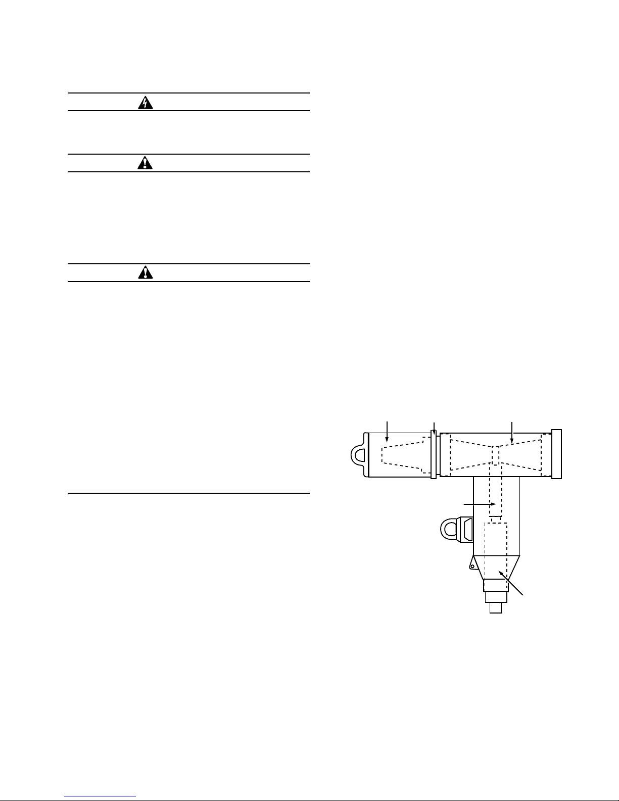
200 A protective cap
Unthreaded Connector
(Compression or
Shear Bolt)
Figure 1. Line illustration of 35 kV BT-TAP Connector
Assembly.
BLRTP
T-body
Cable
Adapter
Read this manual first
Read and understand the contents of this manual and follow
all locally approved procedures and safety practices before
installing or operating this equipment.
600 A 35 kV class BT-TAP connector system installation instructions MN650003EN February 2015
1
IMPORTANT
Installation Instructions to be used for 600 A, 35 kV Class
BT-TAP connector with shear bolt connector. Please see
page 8 for installation instructions using a compression
connector.
ote:N If concentric neutral cable is not being used,
follow cable preparation directions in shield
adapter kit.
Equipment Provided
•
BT-TAP Connector Assembly Kit includes:
• T-body
• Cable Adapter
• Shear Bolt Connector with 11/16” unthreaded spade
• BT-TAP Loadbreak Reducing Tap Plug (BLRTP)
• Extended Length Stud
• 200 A Loadbreak Protective Cap (when furnished)
• Silicone Lubricant
• Instruction Sheets
Installation of connectors
Shear bolt installation procedures
(for compression connector procedures, see page 8)
Prepare the cable
Step 1.
Train cable
•
Position cable vertically so that it is centered between
apparatus bushing and parking pocket, parallel to, and 7"
(178 mm) from apparatus frontplate.
•
Provide adequate cable slack for cable movement
between standoff bushing and apparatus bushing.
•
Support cable as needed to maintain position.
•
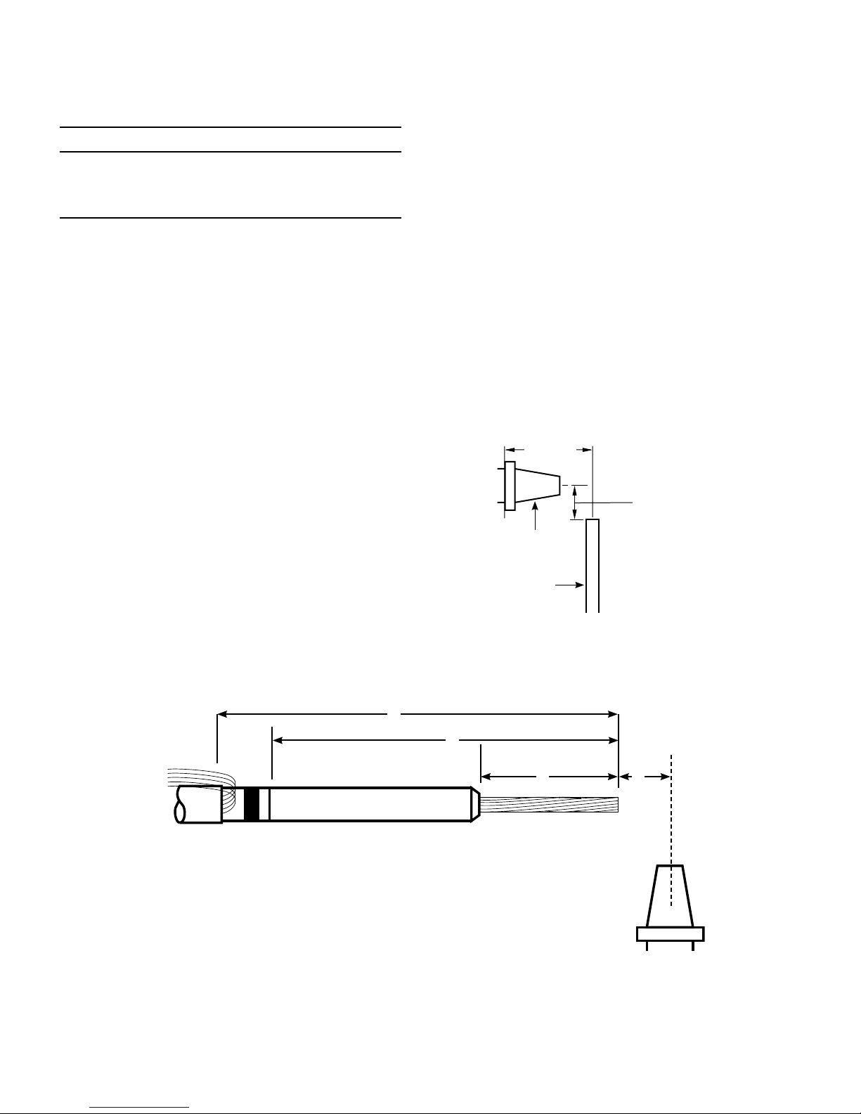
Cut cable to length "A" from centerline of bushing. (Refer
to Fig ure 3 and Table 2 for "A" length.)
7"
(178 mm)
Tools Required
• 5/16” Hex Shaft (Catalog Number HD635)
• Cable Stripping Tools
• Torque Wrench
• 5 mm or 8 mm Allen Wrench
"A"
(See Table 2)
Bushing
Cable
Figure 3. Line illustration for cable training.
B
C
D A
Figure 2. Strip back dimensions.
2
600 A 35 kV class BT-TAP connector system installation instructions for MN650003EN February 2015
 Loading...