

Eaton 75VCPW-VSR, 50VCPW-VSR Instruction Book
Instruction Book IB02707112E
Supersedes May 2014
Effective
August 2015
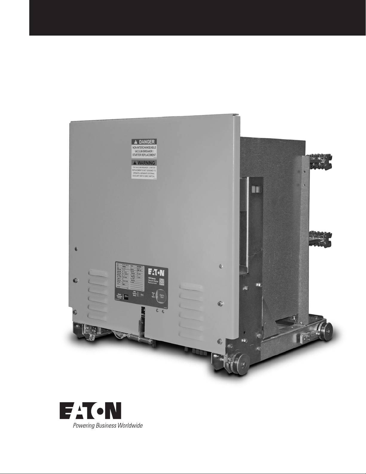
50/75VCPW-VSR
Breaker To Vacuum Starter Replacement Unit
50VCPW-VSR 350 390A Shown

Instruction Book IB02707112E
August 2015
Breaker To Vacuum Starter Replacement Unit
50/75VCPW-VSR
DISCLAIMER OF WARRANTIES AND LIMITATION OF LIABILITY
The information, recommendations, descriptions and safety notations in this document are based on Eaton Corporation’s (“Eaton”)
experience and judgment and may not cover all contingencies. If further information is required, an Eaton sales office should be consulted.
Sale of the product shown in this literature is subject to the terms and conditions outlined in appropriate Eaton selling policies or other
contractual agreement between Eaton and the purchaser.
THERE ARE NO UNDERSTANDINGS, AGREEMENTS, WARRANTIES, EXPRESSED OR IMPLIED, INCLUDING WARRANTIES OF FITNESS
FOR A PARTICULAR PURPOSE OR MERCHANTABILITY, OTHER THAN THOSE SPECIFICALLY SET OUT IN ANY EXISTING CONTRACT
BETWEEN THE PARTIES. ANY SUCH CONTRACT STATES THE ENTIRE OBLIGATION OF EATON. THE CONTENTS OF THIS DOCUMENT
SHALL NOT BECOME PART OF OR MODIFY ANY CONTRACT BETWEEN THE PARTIES.
In no event will Eaton be responsible to the purchaser or user in contract, in tort (including negligence), strict liability or other-wise for any
special, indirect, incidental or consequential damage or loss whatsoever, including but not limited to damage or loss of use of equipment,
plant or power system, cost of capital, loss of power, additional expenses in the use of existing power facilities, or claims against the
purchaser or user by its customers resulting from the use of the information, recommendations and descriptions contained herein. The
information contained in this manual is subject to change without notice.
2
EATON CORPORATION www.eaton.com

50/75VCPW-VSR
Breaker To Vacuum Starter Replacement Unit
Instruction Book IB02707112E
August 2015
WARNING
IMPROPERLY INSTALLING OR MAINTAINING THESE PRODUCTS CAN
RESULT IN DEATH, SERIOUS PERSONAL INJURY OR PROPERTY DAMAGE.
READ AND UNDERSTAND THESE INSTRUCTIONS BEFORE ATTEMPTING
ANY UNPACKING, ASSEMBLY, OPERATION OR MAINTENANCE OF THE
DEVICE.
INSTALLATION OR MAINTENANCE SHOULD BE ATTEMPTED ONLY
BY QUALIFIED PERSONNEL. THIS INSTRUCTION BOOK SHOULD NOT
BE CONSIDERED ALL INCLUSIVE REGARDING INSTALLATION OR
MAINTENANCE PROCEDURES. IF FURTHER INFORMATION IS REQUIRED,
YOU SHOULD CONSULT EATON’S ELECTRICAL SERVICES & SYSTEMS.
THE UNITS DESCRIBED IN THIS BOOK ARE DESIGNED AND TESTED TO
OPERATE WITHIN THEIR NAMEPLATE RATINGS. OPERATION OUTSIDE OF
THESE RATINGS MAY CAUSE THE EQUIPMENT TO FAIL, RESULTING IN
DEATH, BODILY INJURY AND PROPERTY DAMAGE.
ALL SAFETY CODES, SAFETY STANDARDS AND/OR REGULATIONS AS
THEY MAY BE APPLIED TO THIS TYPE OF EQUIPMENT MUST BE STRICTLY
ADHERED TO.
THESE VACUUM STARTER REPLACEMENT UNITS ARE DESIGNED TO
BE INSTALLED PURSUANT TO THE AMERICAN NATIONAL STANDARDS
INSTITUTE (ANSI). SERIOUS INJURY, INCLUDING DEATH, CAN RESULT
FROM FAILURE TO FOLLOW THE PROCEDURES OUTLINED IN THIS
MANUAL.
Contents
Sections
INTRODUCTION .................................. 4
SAFE PRACTICES ................................. 6
RECEIVING, HANDLING, AND STORAGE .............. 7
DESCRIPTION AND OPERATION .....................11
INSPECTION, MAINTENANCE, AND INSTALLATION .....16
REPLACEMENT OF COMPONENTS ................. 20
REMOVAL OF PHASE BARRIERS AND FUSE .......... 25
REPLACEMENT PARTS ........................... 26
This product was manufactured by Eaton Corporation at the
Power Breaker Center (PBC): 310 Maxwell Avenue, Greenwood, SC
29646.
All possible contingencies which may arise during installation,
operation or maintenance, and all details and variations of this
equipment do not purport to be covered by these instructions. If
further information is desired by purchaser regarding his particular
installation, operation or maintenance of particular equipment,
contact a Eaton representative.
EATON CORPORATION www.eaton.com
3

Instruction Book IB02707112E
August 2015
50/75VCPW-VSR
Breaker To Vacuum Starter Replacement Unit
SECTION 1: INTRODUCTION
The purpose of this book is to provide instructions for receiving
and handling, storage, installation, operation and maintenance of
the Westinghouse* type VCP-W Medium Voltage Vacuum Starter
Replacement (also referred to as VSR-Series). The Vacuum Starter
Replacement units are designed to be used in existing type VCP-W
metalclad switchgear and provide equal of superior electrical and
mechanical performance as compared to the design ratings of the
original power circuit breakers when switching motors. VSR-Series
Units provide reliable control, protection and performance, with ease
of handling and maintenance. Like ratings are interchangeable with
each other.
SATISFACTORY PERFORMANCE OF THESE UNITS ARE CONTINGENT
UPON PROPER APPLICATION, CORRECT INSTALLATION AND ADEQUATE
MAINTENANCE. THIS INSTRUCTION BOOK MUST BE CAREFULLY READ
AND FOLLOWED IN ORDER TO OBTAIN OPTIMUM PERFORMANCE FOR
LONG USEFUL LIFE OF THE UNITS. IT IS FURTHER RECOMMENDED THAT
THE INSTALLATION BE PERFORMED BY A EATON CORPORATION TRAINED
ENGINEER OR TECHNICIAN.
VSR-SERIES UNITS ARE PROTECTIVE DEVICES, AS SUCH, THEY ARE
MAXIMUM RATED DEVICES. THEREFORE, THEY SHOULD NOT UNDER ANY
CIRCUMSTANCE BE APPLIED OUTSIDE THEIR NAMEPLATE RATINGS.
WARNING
This book is intended to be used in conjunction with the technical
information provided with the original equipment order which
includes, but is not limited to electrical control schematics and wiring
diagrams, outline diagrams, installation plans, and procedures for
installation and maintenance of accessory items.
Satisfactory performance is dependant upon proper application,
correct installation, and adequate maintenance. It is strongly
recommended that this instruction book be carefully read and
ALL POSSIBLE CONTINGENCIES WHICH MIGHT ARISE DURING
INSTALLATION, OPERATION, OR MAINTENANCE, AND ALL DETAILS
AND VARIATIONS OF THIS EQUIPMENT ARE NOT COVERED BY THESE
INSTRUCTIONS. IF FURTHER INFORMATION IS DESIRED BY THE
PURCHASER REGARDING A PARTICULAR INSTALLATION, OPERATION, OR
MAINTENANCE OF THIS EQUIPMENT, THE LOCAL EATON’S ELECTRICAL
SERVICES & SYSTEMS REPRESENTATIVE SHOULD BE CONTACTED.
followed in order to realize optimum performance and long useful life
of the unit.
ote:N * Westinghouse may also be designated as Cutler-Hammer and/or
Eaton.
1.1 AVAILABLE VCPW-VSR UNITS
Refer to Table 1.1
Table 1. VCPW-VSR Availability and Interchangeability
Original Breaker Type MV-VSR Breaker
To Vacuum Starter
Replacement Unit
50VCP-W 250-1200A 50VCPW-VSR-250-290A 60 4.76 400 230 50 230
50VCP-W 250-1200A 50VCPW-VSR-250-390A 60 4.76 400 390 50 390
50VCP-W 350-1200A 50VCPW-VSR-350-290A 60 4.76 400 230 50 230
50VCP-W 350-1200A 50VCPW-VSR-350-390A 60 4.76 400 390 50 390
75VCP-W 500-1200A 75VCPW-VSR-500-290A 60 7.2 400 230 50 230
75VCP-W 500-1200A 75VCPW-VSR-500-390A 60 7.2 400 390 50 390
BIL
kV
Rated Maximum kVContactor Amps Maximum Fuse
Rating Amps
Fused Short
Circuit Rating
kA
Maximum
Continuous
Amps
4
EATON CORPORATION www.eaton.com
50/75VCPW-VSR
Breaker To Vacuum Starter Replacement Unit
Instruction Book IB02707112E
August 2015
B
D
C C
E
A
F
G
JI
H
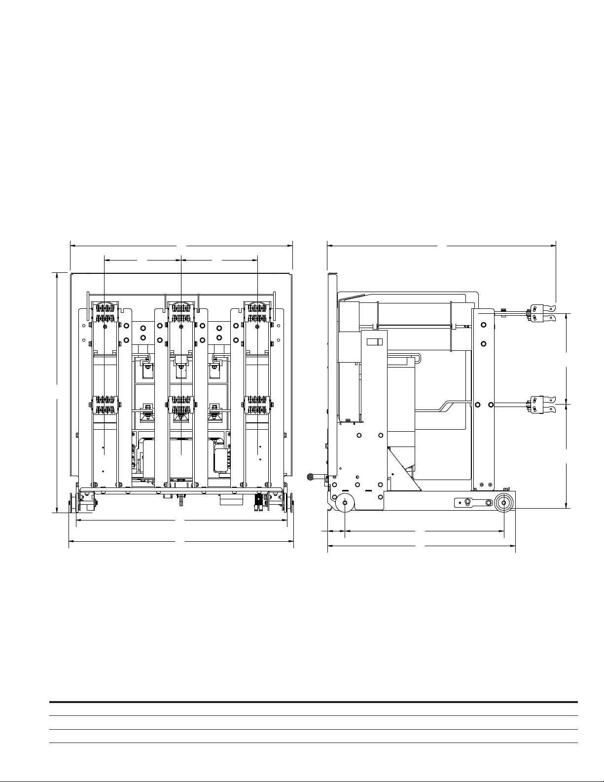
K
Table 2. VCPW-VSR Dimensions
Existing Breaker
Rated Continuous
Device Type
50VCPW-VSR 250 230A / 390A 29.44 29.12 10.00 29.81 12.00 13.63 27.80 29.56 2.25 20.88 24.63
50VCPW-VSR 350 230A / 390A 31.44 29.12 10.00 29.94 12.00 13.63 27.80 29.56 2.25 20.88 24.63
75VCPW-VSR 500 230A / 390A 29.44 29.12 10.00 29.81 12.00 13.63 27.80 29.56 2.25 20.88 24.63
Current at 60 Hz
(Amps) A B C D E F G H I J K
EATON CORPORATION www.eaton.com
5

Instruction Book IB02707112E
August 2015
SECTION 2: SAFE PRACTICES
VSR-Series units are equipped with high speed, high energy
operating mechanisms. They are designed with several built-in
interlocks and safety features to provide safe and proper operating
sequences.
WARNING
TO PROTECT THE PERSONNEL ASSOCIATED WITH INSTALLATION,
OPERATION, AND MAINTENANCE OF THESE UNITS, THE FOLLOWING
PRACTICES MUST BE FOLLOWED:
•
Only qualified persons, as defined in the National Electrical
Safety Code, who are familiar with the installation and
maintenance of medium voltage circuits and equipment,
should be permitted to work on these units.
•
Read these instructions carefully before attempting any
installation, operation or maintenance of these units.
•
Always remove the unit from the enclosure before
performing any maintenance. Failure to do so could result in
electrical shock leading to death, severe personnel injury or
property damage.
•
Do not work on a unit with the secondary test coupler
engaged. Failure to disconnect the test coupler could result
in an electrical shock leading to death, personnel injury or
property damage.
•
Do not work on a closed unit. The main contacts should be
open before working on the unit. Failure to do so could result
in cutting or crushing injuries.
•
Do not use a MV-VSR by itself as the sole means of isolating
a high voltage circuit. Remove the unit to the Disconnect
position and follow all lockout and tagging rules of the
National Electrical Code and any and all applicable codes,
regulations and work rules.
•
Do not leave the unit in an intermediate position in the
cell. Always have the unit either in the Test or Connected
position. Failure to do so could result in a flash over and
possible death, personnel injury or property damage.
•
These units are equipped with safety interlocks. Do not
defeat them. This may result in death, bodily injury or
equipment damage.
50/75VCPW-VSR
Breaker To Vacuum Starter Replacement Unit
6
EATON CORPORATION www.eaton.com
50/75VCPW-VSR
Breaker To Vacuum Starter Replacement Unit
Instruction Book IB02707112E
August 2015
SECTION 3: RECEIVING, HANDLING, AND
STORAGE
Type VCP-W VSR-series breaker to vacuum starter replacement units
are subjected to complete factory production tests and inspection
before being packed. They are shipped in packages designed to
provide maximum protection to the equipment during shipment
and storage and at the same time to provide convenient handling.
Accessories such as the cell code plate, etc. are shipped with the
unit (Figure 3.1).
3.1 RECEIVING
Until the unit is ready to be delivered to the switchgear site for
installation, DO NOT remove it from the shipping crate. If the unit
is to be placed in storage, maximum protection can be obtained by
keeping it in its crate.
Upon receipt of the equipment, inspect the crates for any signs of
damage or rough handling. Open the crates carefully to avoid any
damage to the contents. Use a nail puller rather than a crow bar
when required.
When opening the crates, be careful that any loose items or
hardware are not discarded with the packing material. Check the
contents of each package against the packing list.
Examine the unit for any signs of shipping damage such as broken,
missing or loose hardware, damaged or deformed insulation and
other components. File claims immediately with the carrier if
damaged or loss is detected and notify the nearest Eaton’s Electrical
Services & Systems office.
3.2 HANDLING
WARNING
DO NOT USE ANY LIFTING DEVICE AS A PLATFORM FOR PERFORMING
MAINTENANCE, REPAIR OR ADJUSTMENT OF THE UNIT OR FOR OPENING,
CLOSING THE CONTACTS OR CHARGING THE SPRINGS. THE UNIT MAY
SLIP OR FALL CAUSING SEVERE PERSONAL INJURY. ALWAYS PERFORM
MAINTENANCE, REPAIR AND ADJUSTMENTS ON A WORKBENCH
CAPABLE OF SUPPORTING THE UNIT.
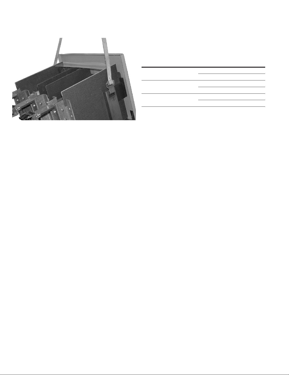
VCPW-VSR unit shipping containers are designed to be handled
either by use of a rope sling and overhead lifting device or by a
fork lift truck. If containers must be skidded for any distance, it is
preferable to use roller conveyors or individual pipe rollers.
Once the unit has been inspected for shipping damage, it is best to
return it to its original shipping crate until it is ready to be installed in
the Metal-Clad Switchgear.
When the unit is ready for installation, a lifting harness in conjunction
with an overhead lift or portable floor lift can be used to move the
unit, if this is preferable to rolling the unit on the floor using self
contained wheels. If the unit is to be lifted, position the lifting device
(lifting straps should have at least a 1600 pound capacity) over the
unit and insert the lifting harness hooks into the unit side openings
and secure. Be sure the hooks are firmly attached before lifting
the unit. Stand a safe distance away from the unit while lifting and
moving.
Tools and Accessories
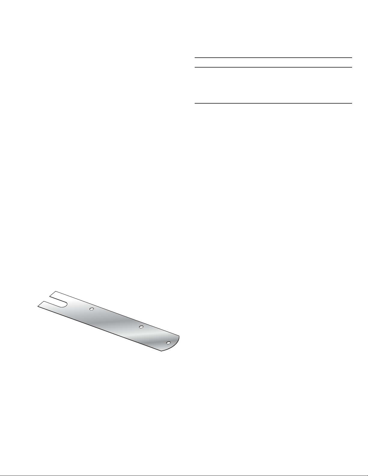
Contact Wear Gauge: Optional item used to check contact wear.
(Style 5259C11H01) (See Section 5)
Racking Handle: The original VCP-W racking handle is used to assist
in moving the MV-VSR into and out of the cell.
Lifting Yoke: Optional lifting device that can be used to install a VSR
into upper compartment of VCP-W switchgear. (Style 94M7103G99)
Figure 3.1. Contact Wear Gauge
EATON CORPORATION www.eaton.com
7
Instruction Book IB02707112E
August 2015
50/75VCPW-VSR
Breaker To Vacuum Starter Replacement Unit
Figure 3.2. Lifting VCPW-VSR
3.3 STORAGE
If the MV-VSR is to be placed in storage, maximum protection
can be obtained by keeping it in the original shipping crate. Before
placing it in storage, checks should be made to make sure that the
unit is free from shipping damage and is in satisfactory operating
condition.
The unit is shipped with its contacts open, the indicators on
the front panel should confirm this. Outdoor storage is NOT
recommended. If unavoidable, the outdoor location must be well
drained and a temporary shelter from sun, rain, snow, corrosive
fumes, dust, dirt, falling objects, excessive moisture, etc. must be
provided. Containers should be arranged to permit free circulation of
air on all sides and temporary heaters should be used to minimize
condensation. Moisture can cause rusting of metal parts and
deterioration of high voltage insulation. A heat level of approximately
400 watts for each 100 cubic feet of volume is recommended with
the heaters distributed uniformly throughout the structure near the
floor.
3.4 VCPW-VSR APPROXIMATE WEIGHTS
Refer to Table 3.
Table 3. Maximum Weight by Type
Type Amperes LBs
50VCPW-VSR 250 230 290
390 310
50VCPW-VSR 350 230 290
390 310
75VCPW-VSR 500 230 290
390 310
Indoor storage should be in a building with sufficient heat and
circulation to prevent condensation. If the building is not heated, the
same general rule for heat as for outdoor storage should be applied.
8
EATON CORPORATION www.eaton.com
50/75VCPW-VSR
Breaker To Vacuum Starter Replacement Unit
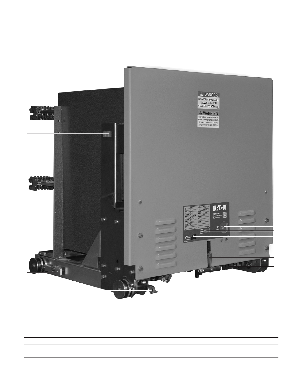
Figure 3.3. Front External View of 50VCPW-VSR
1
Instruction Book IB02707112E
August 2015
2
3
Front External View
1 Lifting Point 4 Push To Open Button 7 Lift / Pull Handle
2 Extension Rail Interlock 5 Main Contact Status 8 Code Plate
3 Ground Contact 6 Starter Operations Counter
4
5
6
7
8
EATON CORPORATION www.eaton.com
9
 Loading...