

Eaton 50VCPW350, 75VCPW500, 50VCPW250, 50VCPWND250, 150VCPW500 Instructions For Installation/operation/maintenance/servicing
...
Instruction Booklet IB131006EN
Effective March 2019
Supersedes July 2017
Instructions for installation,
operation, and maintenance of type
VCP-W vacuum circuit breakers

Instruction Booklet IB131006EN
Effective March 2019
Instructions for installation,
operation, and maintenance of type
VCP-W vacuum circuit breakers
m WARNING
IMPROPERLY INSTALLING OR MAINTAINING THESE PRODUCTS CAN
RESULT IN DEATH, SERIOUS PERSONAL INJURY, OR PROPERTY DAMAGE.
READ AND UNDERSTAND THESE INSTRUCTIONS BEFORE ATTEMPTING
ANY UNPACKING, ASSEMBLY, OPERATION OR MAINTENANCE OF THE
CIRCUIT BREAKERS.
INSTALLATION OR MAINTENANCE SHOULD BE ATTEMPTED ONLY
BY QUALIFIED PERSONNEL. THIS INSTRUCTION BOOK SHOULD NOT
BE CONSIDERED ALL INCLUSIVE REGARDING INSTALLATION OR
MAINTENANCE PROCEDURES. IF FURTHER INFORMATION IS REQUIRED,
YOU SHOULD CONTACT EATON.
m WARNING
THE CIRCUIT BREAKER ELEMENTS DESCRIBED IN THIS BOOK ARE
DESIGNED AND TESTED TO OPERATE WITHIN THEIR NAMEPLATE
RATINGS. OPERATION OUTSIDE OF THESE RATINGS MAY CAUSE THE
EQUIPMENT TO FAIL, RESULTING IN DEATH, SERIOUS PERSONAL INJURY,
AND PROPERTY DAMAGE.
ALL SAFETY CODES, SAFETY STANDARDS, AND/OR REGULATIONS AS
THEY MAY BE APPLIED TO THIS TYPE OF EQUIPMENT MUST BE STRICTLY
ADHERED TO.
THESE CIRCUIT BREAKER ELEMENTS ARE DESIGNED TO BE INSTALLED
PURSUANT TO THE AMERICAN NATIONAL STANDARDS INSTITUTE (ANSI).
SERIOUS INJURY, INCLUDING DEATH, CAN RESULT FROM FAILURE TO
FOLLOW THE PROCEDURES OUTLINED IN THIS MANUAL. THESE CIRCUIT
BREAKER ELEMENTS ARE SOLD PURSUANT TO A NON-STANDARD
PURCHASING AGREEMENT WHICH LIMITS THE LIABILITY OF THE
MANUFACTURER.
These instructions do not purport to cover
all possible contingencies, details, and
variations which may arise during installation, operation or maintenance. If further
information is desired by purchaser regarding his particular installation, operation or
maintenance of particular equipment, contact an Eaton representative.
2
EATON www.eaton.com

Instructions for installation,
Instruction Booklet IB131006EN
operation, and maintenance of type
VCP-W vacuum circuit breakers
Contents
Description Page
1. Introduction .......................................................................6
1.1 Preliminary comments and safety pre-cautions ......................................... 6
1.1.1 Warranty and liability information .................................................6
1.1.2 Safety precautions ............................................................ 6
1.2 General information ..............................................................6
1.3 Type VCP-W vacuum circuit breaker element ratings (Tables 1, 2, 3, 4, 5, and 6) ............... 7
1.4 Outlines and dimensions ......................................................... 11
2. Safe practices .................................................................... 13
2.1 Recommendations .............................................................. 13
3. Receiving, handling, and storage ..................................................... 13
3.1 General ....................................................................... 13
3.2 Receiving ..................................................................... 13
3.3 Handling ...................................................................... 13
3.4 Storage ....................................................................... 13
3.5 Tools and accessories. . . . . . . . . . . . . . . . . . . . . . . . . . . . . . . . . . . . . . . . . . . . . . . . . . . . . . . . . . . . 14
3.6 Type VCP-W vacuum circuit breaker element weights (Tables 18, 19, and 20). ................ 21
4. Initial inspection and installation ...................................................... 28
4.1 Introduction ...................................................................28
4.2 Manual operation check .......................................................... 28
4.3 Vacuum interrupter integrity ....................................................... 28
4.4 Insulation ..................................................................... 28
4.5 Contact erosion and wipe ........................................................28
4.6 Primary circuit resistance ......................................................... 28
4.7 Nameplate .................................................................... 28
4.8 Electrical operation check ........................................................28
4.8.1 Circuit breaker insertion and removal ............................................ 28
4.8.2 Circuit breaker performance check .............................................. 33
4.9 Circuit breaker/structure interfacing ................................................. 34
4.9.1 Interface interlocks/interfacing check ............................................34
5. Description and operation ........................................................... 36
5.1 Introduction ...................................................................36
5.2 Interrupter assembly ............................................................ 36
5.2.1 Vacuum interrupter ..........................................................37
5.2.2 Contact erosion indication ..................................................... 37
5.2.3 Loading spring indicator .......................................................37
5.2.4 Contact wipe and stroke ...................................................... 37
5.2.5 Phase barriers .............................................................. 37
5.3 Stored energy mechanism ........................................................38
5.3.1 Operation of stored energy mechanism ..........................................38
5.3.2 Charging ..................................................................41
5.3.3 Closing operation ............................................................ 41
5.3.4 Tripping operation ............................................................ 41
5.3.5 Trip free operation ........................................................... 41
5.4 Control schemes ............................................................... 41
5.4.1 Timing .................................................................... 45
5.4.2 Secondary disconnects ....................................................... 45
5.4.3 Shunt trip device ............................................................45
5.4.4 Under-voltage trip device ...................................................... 45
5.5 Interlocks and interfacing .........................................................47
5.6 Levering mechanism ............................................................ 47
5.7 Operations counter ............................................................. 47
5.8 Ground contact ................................................................47
5.9 MOC and TOC switch operations .................................................. 47
Effective March 2019
EATON www.eaton.com
3

Instruction Booklet IB131006EN
Effective March 2019
operation, and maintenance of type
VCP-W vacuum circuit breakers
6. Inspection, maintenance, and troubleshooting ........................................... 48
6.1 Introduction ...................................................................48
6.2 Frequency of inspection and maintenance ...........................................48
6.2.1 Qualified personnel .......................................................... 48
6.2.2 General torque guidelines ..................................................... 49
6.3 Inspection and maintenance procedures ............................................. 50
6.4 Vacuum interrupter integrity test ................................................... 51
6.5 Contact erosion and wipe ........................................................51
6.6 Insulation ..................................................................... 53
6.7 Insulation integrity check ......................................................... 53
6.8 Primary circuit resistance check ................................................... 53
6.9 Mechanism check .............................................................. 53
6.9.1 CloSure™ test .............................................................. 53
6.10 Megger and power factor testing ................................................. 53
6.11 Mechanism lubrication .......................................................... 57
6.12 Finger clusters and switchgear stab lubrication ....................................... 57
6.13 Main contacts to switchgear primary engagement .................................... 57
6.14 How to determine the manufacturing date ..........................................57
6.15 Troubleshooting chart ...........................................................58
6.16 End of life procedures ..........................................................58
6.17 Failure reporting ............................................................... 58
7. Renewal parts .................................................................... 59
7.1 General ....................................................................... 59
7.1.1 Ordering instructions ......................................................... 59
8. Optional accessories ............................................................... 70
8.1 Optional factory installed roll-on-floor wheel kit .......................................70
8.2 Optional automatic/manual hybrid secondary for BPI pan assembly .......................70
8.3 Optional 3,000 A ball screw drive for BPI pan assembly .................................71
List of figures
Figure Title Page
Figure 1. Type VCP-W, VCPW-SE, and VCP-WC circuit breaker outlines & dim. in inches (mm). ........ 11
Figure 2. Type VCPW-ND circuit breaker outlines and dimensions in inches (mm). ................. 12
Figure 3. Typical VCP-W tools and accessories. ............................................23
Figure 4. Typical front view VCP-W vacuum circuit breaker. ................................... 24
Figure 5. Typical VCP-W vacuum circuit breaker element with front cover removed. ................25
Figure 6. Typical rear view VCP-W vacuum circuit breaker element. ............................. 26
Figure 7. Typical VCP-W vacuum circuit breaker front cover arrangement. ........................27
Figure 8. Type VCP-W circuit breaker manual charging handle in use. ........................... 28
Figure 9. Insertion of the drawout extension rails. ..........................................29
Figure 10. Lifting and setting the breaker in the housing. ..................................... 29
Figure 11. Front panel. ................................................................ 30
Figure 12. BPI pan assembly. .......................................................... 31
Figure 13. Non-BPI pan assembly. ......................................................32
Figure 14. Engaging extension rails in a lower circuit breaker compartment. ..................... 34
Figure 15. Typical VCP-W circuit breaker bottom view. ....................................... 34
Figure 16. Pulling secondary disconnect cage to engage secondaries in TEST position. ............. 35
Figure 17. Engaging levering-in crank. ....................................................35
Figure 18. Typical VCP-W rear view showing vacuum interrupters and current carrying system. ....... 36
Figure 19. Graphic representation of arc interruption. ....................................... 37
Figure 20. Closing cam and trip linkage. .................................................. 39
Figure 21. Charging schematic. .........................................................40
Figure 22. Typical VCP-W DC and AC control schemes. ...................................... 42
Figure 23. 15 kV VCP-WXC 63 kA 1200-3000 A special power plant breakers ....................43
Figure 23. 5 kV VCP-WXC 63 kA 1200-3000 A special power plant breakers. ..................... 44
Figure 24. 15 kV under-voltage trip device configuration. ..................................... 46
Figure 25. Lubrication points. ..........................................................49
Instructions for installation,
4
EATON www.eaton.com

Instructions for installation,
Instruction Booklet IB131006EN
operation, and maintenance of type
VCP-W vacuum circuit breakers
Figure 26. 50 VCP-W 63 - 63 kA pole unit. ................................................49
Figure 27. Vacuum interrupter showing contact erosion indicator with breaker open ...............52
Figure 28. Vacuum interrupter showing contact erosion indicator with breaker closed. ............. 52
Figure 29. Wipe indication procedure. ....................................................52
Figure 30. Starting tape at the bottom of the cam. ......................................... 54
Figure 31. Wrapping tape up around the cam. ............................................. 54
Figure 32. Attaching tape around to the back of the cam. .................................... 54
Figure 33. Attaching CloSure test tool at hole “A”. ........................................... 54
Figure 34. Attaching CloSure test tool at “B”. ..............................................54
Figure 35. Manually charging the closing springs. ..........................................55
Figure 36. Manually closing the circuit breaker with the marker in hole “C”. ......................55
Figure 37. Top view of the cam and marker interface. ........................................55
Figure 38. Move marker 15° to the right. ................................................. 55
Figure 39. Move marker 15° to the left. .................................................. 55
Figure 40. Remove marked masking tape from the cam. ..................................... 56
Figure 41. Place the tape on the right side panel of the breaker. ...............................56
Figure 42. Illustrative testing tape sample. ................................................ 56
Figure 43. Front view of closure tool showing mounting/testing locations (6352C49H01). ........... 56
Figure 44. Typical circuit breaker front view with CloSure tool attached. ......................... 56
Figure 45. Roll-on-floor wheel kit (shown installed on a standard 5/15 kV VCP-W breaker). .......... 70
Figure 46. Optional automatic/manual secondary for BPI pan assembly. .........................71
List of tables
Table Title Page
Table 1. (ANSI Standardsa) type VCP-W vacuum circuit breaker through 15 kV
Table 2. (ANSI Standardsa) type VCP-W vacuum circuit breaker 27 kV rated symmetrical current basis. 8
Table 3. (ANSI Standards) type VCP-WC extra capability vacuum circuit breaker 5-27 kV
Table 4. (IEC-56 Standardsa) type VCP-W vacuum circuit breaker through 17.5 kV
Table 5. (ANSI Standardsa) type VCP-W (K = 1) vacuum circuit breaker through 15 kV
Table 6. (ANSI Standardsa) type VCP-WXC circuit breaker through 15 kV
Table 7. Accessories for 36-inch wide breaker compartments for 29-inch frame breaker. .......... 15
Table 8. Narrow design accessories for 26-inch-wide breaker compartments. ...................16
Table 9. 27 kV VCP-W accessories. ..................................................... 17
Table 10. Simple manual ground and test devices—bus bar type. .............................18
Table 11. 15 kV VCP-W simple manual ground and test device—“bail” and “ball” type a . ...........18
Table 12. Complex manual (selectable) ground and test device. ............................... 18
Table 13. Simple electrically operated ground and test device. ................................ 19
Table 14. Simple electrically operated ground and test device for VCP-W without key interlocks. .....20
Table 15. Simple electrically operated ground and test device for VCP-WXC. .....................20
Table 16. 27 kV manual ground and test device. ........................................... 20
Table 17. Dummy elements
Table 18. VCP-W ANSI rated breaker weightsa.. . . . . . . . . . . . . . . . . . . . . . . . . . . . . . . . . . . . . . . . . . . . 21
Table 19. VCP-W IEC rated breaker weightsa. ............................................. 22
Table 20. VCP-W (K = 1) breaker weightsa. ............................................... 22
Table 21. VCP-W & VCP-WC circuit breaker barrier configurations. ............................. 38
Table 22. Circuit breaker timing. ........................................................ 45
Table 23. Torque guidelines. ...........................................................49
Table 24. Test voltage (insulation and vacuum integrity). ..................................... 51
Table 25. Typical resistance measurements. .............................................. 53
Table 26. Closure tool mounting/testing locations by circuit breaker type. .......................57
Table 27. Recommended renewal parts for ANSI rated breakers .............................. 59
Table 28. Recommended renewal parts for IEC rated breakers ................................ 65
Table 29. Recommended renewal parts for GB rated breakers ................................ 69
rated symmetrical current basis. ................................................. 7
rated symmetrical current basis. ................................................. 9
rated symmetrical current basis. ................................................ 9
rated symmetrical current basis (standard ratings). ................................. 10
rated symmetrical current basis (standard ratings). ................................. 10
a .......................................................... 21
Effective March 2019
EATON www.eaton.com
5

Instruction Booklet IB131006EN
Effective March 2019
Instructions for installation,
operation, and maintenance of type
VCP-W vacuum circuit breakers
1. Introduction
1.1 Preliminary comments and safety pre-cautions
This technical document is intended to cover most aspects associated with the installation, operation, and maintenance of Type
VCP-W, VCPW-SE, VCP-WC,and VCPWND vacuum circuit breakers.
It is provided as a guide for authorized and qualified personnel only.
Please refer to the specific WARNING and CAUTION in Paragraph
1.1.2 before proceeding past Section 1. If further information is
required by the purchaser regarding a particular installation, application, or maintenance activity, an Eaton representative should be
contacted.
1.1.1 Warranty and liability information
NO WARRANTIES, EXPRESSED OR IMPLIED, INCLUDING WARRANTIES
OF FITNESS FOR A PARTICULAR PURPOSE OF MERCHANTABILITY, OR
WARRANTIES ARISING FROM COURSE OF DEALING OR USAGE OF TRADE,
ARE MADE REGARDING THE INFORMATION, RECOMMENDATIONS
AND DESCRIPTIONS CONTAINED HEREIN. In no event will Eaton be
responsible to the purchaser or user in contract, in tort (including
negligence), strict liability or otherwise for any special, indirect, incidental, or consequential damage or loss whatsoever, including but
not limited to damage or loss of use of equipment, plant or power
system, cost of capital, loss of power, additional expenses in the
use of existing power facilities, or claims against the purchaser or
user by its customers resulting from the use of the information and
descriptions contained herein.
1.1.2 Safety precautions
All safety codes, safety standards, and/or regulations must be
strictly observed in the installation, operation, and maintenance of
this device.
1.2 General information
The purpose of this book is to provide instructions for unpacking, storage, use, operation, and maintenance of Type VCP-W,
VCPW-SE, VCP-WC, and VCPW-ND vacuum circuit breakers. These
circuit breakers are horizontal drawout type removable interrupting
elements designed for use in VacClad-W Metal-Clad switchgear
and appropriate VCP-W modules. They provide reliable control and
protection for medium voltage electrical equipment and circuits. All
VCP-W circuit breaker elements are designed to ANSI Standards for
reliable performance, ease of handling, and simplified maintenance.
In addition, some VCP-W circuit breakers have been tested in accordance with IEC Standards for applications around the world.
The VCPW-SE circuit breaker element is a VCP-W circuit breaker
designed specifically for special environment applications and operating conditions through 27 kV. The VCPW-ND circuit breaker element
is a narrow design VCP-W circuit breaker designed specifically for
use in 5 kV applications where floor space requirements would
not allow the industry standard 36 in. (914.4 mm) wide switchgear.
From this point on, all circuit breaker elements will be referred to as
Type VCP-W unless the reference is specific to a particular design.
The VCP-WC circuit breaker element is a VCP-W circuit breaker
designed and tested for extra capabilities beyond one or more of the
preferred ratings of the applicable ANSI Standard.
m WARNING
SATISFACTORY PERFORMANCE OF THESE BREAKERS IS CONTINGENT
UPON PROPER APPLICATION, CORRECT INSTALLATION, AND ADEQUATE
MAINTENANCE. THIS INSTRUCTION BOOK MUST BE CAREFULLY READ
AND FOLLOWED IN ORDER TO OBTAIN OPTIMUM PERFORMANCE FOR
LONG USEFUL LIFE OF THE CIRCUIT BREAKER ELEMENTS.
m WARNING
THE WARNINGS AND CAUTIONS INCLUDED AS PART OF THE
PROCEDURAL STEPS IN THIS DOCUMENT ARE FOR PERSONNEL SAFETY
AND PROTECTION OF EQUIPMENT FROM DAMAGE. AN EXAMPLE OF A
TYPICAL WARNING LABEL HEADING IS SHOWN ABOVE TO FAMILIARIZE
PERSONNEL WITH THE STYLE OF PRESENTATION. THIS WILL HELP TO
INSURE THAT PERSONNEL ARE ALERT TO WARNINGS, WHICH MAY
APPEAR THROUGHOUT THE DOCUMENT. IN ADDITION, CAUTIONS ARE
ALL UPPER CASE AND BOLDFACE AS SHOWN BELOW.
m CAUTION
COMPLETELY READ AND UNDERSTAND THE MATERIAL PRESENTED IN
THIS DOCUMENT BEFORE ATTEMPTING INSTALLATION, OPERATION,
OR APPLICATION OF THE EQUIPMENT. IN ADDITION, ONLY QUALIFIED
PERSONS SHOULD BE PERMITTED TO PERFORM ANY WORK ASSOCIATED
WITH THE EQUIPMENT. ANY WIRING INSTRUCTIONS PRESENTED IN THIS
DOCUMENT MUST BE FOLLOWED PRECISELY. FAILURE TO DO SO COULD
CAUSE PERMANENT EQUIPMENT DAMAGE.
m WARNING
THE CIRCUIT BREAKERS DESCRIBED IN THIS BOOK ARE DESIGNED AND
TESTED TO OPERATE WITHIN THEIR NAMEPLATE RATINGS. OPERATION
OUTSIDE OF THESE RATINGS MAY CAUSE THE EQUIPMENT TO FAIL,
RESULTING IN DEATH, BODILY INJURY, AND PROPERTY DAMAGE.
6
EATON www.eaton.com
Instructions for installation,
Instruction Booklet IB131006EN
operation, and maintenance of type
VCP-W vacuum circuit breakers
1.3 Type VCP-W vacuum circuit breaker element ratings (Tables 1, 2, 3, 4, 5, and 6)
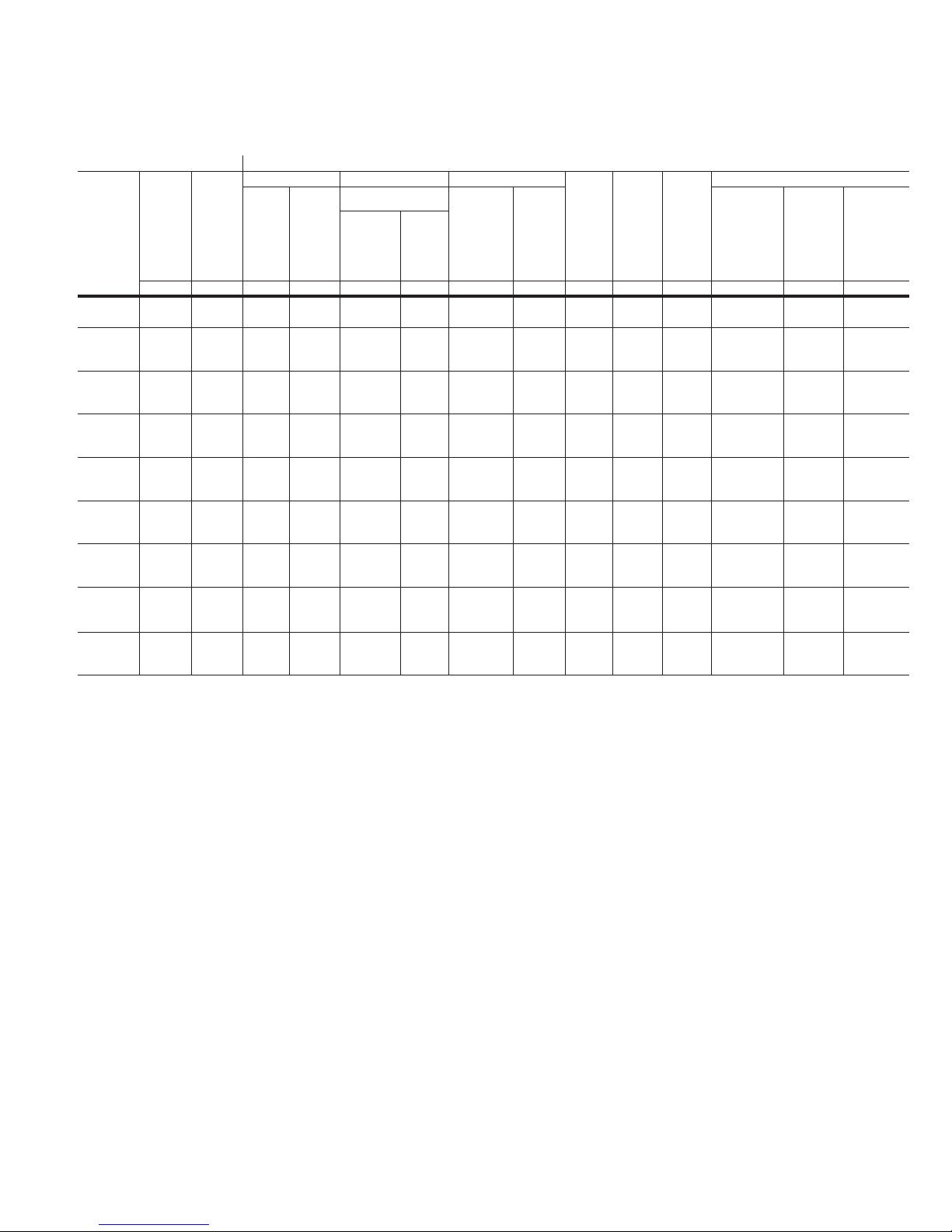
Table 1. (ANSI Standardsa) type VCP-W vacuum circuit breaker through 15 kV rated symmetrical current basis.
Identification Rated values
Circuit
breaker
type
50VCPWND250
50VCPW250
50VCPW350
50VCPW63 (500)
75VCPW500
150 VCP W500
150 VCP W750
150 VCP W1000
150 VCP W63(1500)
a
All circuit breakers are tested to 60 Hz; however, they can also be applied at 50 Hz with no derating.
b
Non-standard circuit breakers with high close and latch (momentary). Rating for special applications.
c
Consult the Consulting Application Guide CA08104001E sections 1 and 5 for further information.
d
e
Nominal
voltage
class
kV MVA kV rms kV rms Amperes kA rms Cycles Seconds kV rms kA rms kA peak kA r ms
Nominal
3-phase
MVA
class
Voltage Insulation level Current Inter-
Max.
voltage
E
Voltage
range
factor
K
Withstand test
voltage
c
Power
frequency
(1 min .)
Impulse
Continuous
current
at 60 Hz
Short
circuit
current
(at rated
max. kV )
I
rupting
time
d
Permissible
tripping
delay
Y
Max.
voltage
divided
by K
E/K
Current values
Maximum
symmetrical
interrupting
capability
K times
rated short
circuit
ce
curre nt
4.16 250 4.76 1.24 19 60 1200 29 5 2 3.85 36 97 58
4.16 250 4.76 1.24 19 60 1200
29 5 2 3.85 36 97
2000
3000
4.16 350 4.76 1.19 19 60 12 00
41 5 2 4.0 49 132 78
2000
3000
4.16 500 4.76 1.00 19 60 12 00
63 5 2 4.76 63 173 101
2000
3000
7.2 500 8.25 1.25 36 95 1200
33 5 2 6.6 41 111 66
2000
3000
13.8 500 15 1.3 0 36 95 120 0
18 5 2 11.5 23 62
2000
3000
13.8 750 15 1.30 36 95 1200
28 5 2 11.5 36 97
2000
3000
13.8 1000 15 1.30 36 95 120 0
37 5 2 11.5 48 130 77
2000
3000
13.8 1500 15 1.00 36 95 120 0
63 5 2 15.0 63 173 101
2000
3000
Optional interrupting time of 3 cycles is available.
Also 3-second shor t time current carrying capability.
Effective March 2019
Closing &
latching
capability
2.7 K
times
rated
short
circuit
current
132
97
130
Closing &
latching
capability
momentary
1.6 K
times rated
short
circuit
current
58
b
b
b
78
37
58
58
77
b
b
b
EATON www.eaton.com
7
Instruction Booklet IB131006EN
Effective March 2019
operation, and maintenance of type
Instructions for installation,
VCP-W vacuum circuit breakers
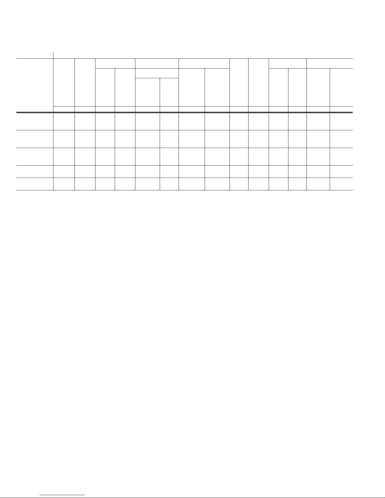
Table 2. (ANSI Standardsa) type VCP-W vacuum circuit breaker 27 kV rated symmetrical current basis.
Identification Rated values
Circuit
breaker
type
270VCPW750(16)
270VCPW1000(22)
270VCPW1250(25)
270VCPW1600(3 2)
270VCPW2000(40)
a
All circuit breakers are tested to 60 Hz; however, they can also be applied at 50 Hz with no derating.
b
K=1.0, therefore E = E/K and I = KI. Consult the Consulting Application Guide CA08104 001E sections 1 and 5 for further information.
c
Consult the Consulting Application Guide CA08104001E sections 1 and 5 for fur ther information.
d
Optional interrupting time of 3 cycles is available.
e
Tested at 28.5 kV RMS.
f
Tested at 29.5 kV RMS.
Nominal
voltage
class
kV MVA kV rms kV rms Amperes kA rms Cycle s Seconds kV rms kA rms kA peak kA rms
27 750 27 1.0 60 12 5 600
e
Nominal
3-phase
MVA
class
Voltage Insulation level Current Inter-
Max.
voltage
E
b
Voltage
range
factor
K
Withstand test
voltage
c
Power
frequency
(1 min .)
Impulse
Continuous
current
at 60 Hz
Short
circuit
current
3 Second
short time
current
carrying
capability
I
rupting
time
16 5 2 51 105 43 31.5
1200
d
Permissible
tripping
delay
Y
Transient
recovery voltage
E
2000
27 1000 27 1.0 60 125 600
e
1200
22 5 2 51 105 60 31.5
2000
27 1250 27 1.0 60 125 600
e
1200
25 5 2 51 105 68 31.5
2000
27 1600 27 1.0 60 12 5 1200
f
27 2000 27 1.0 60 125 1200
f
2000
2000
31.5 5 2 51 10 5 85 31.5
40 5 2 51 105 10 6 31.5
Current values
t
2
2
rise
time
Closing &
latching
capability
2.7 K
times
rated
short
circuit
current
Capacitor
switching
& cabl e
charging
8
EATON www.eaton.com
Instructions for installation,
operation, and maintenance of type
Instruction Booklet IB131006EN
Effective March 2019
VCP-W vacuum circuit breakers
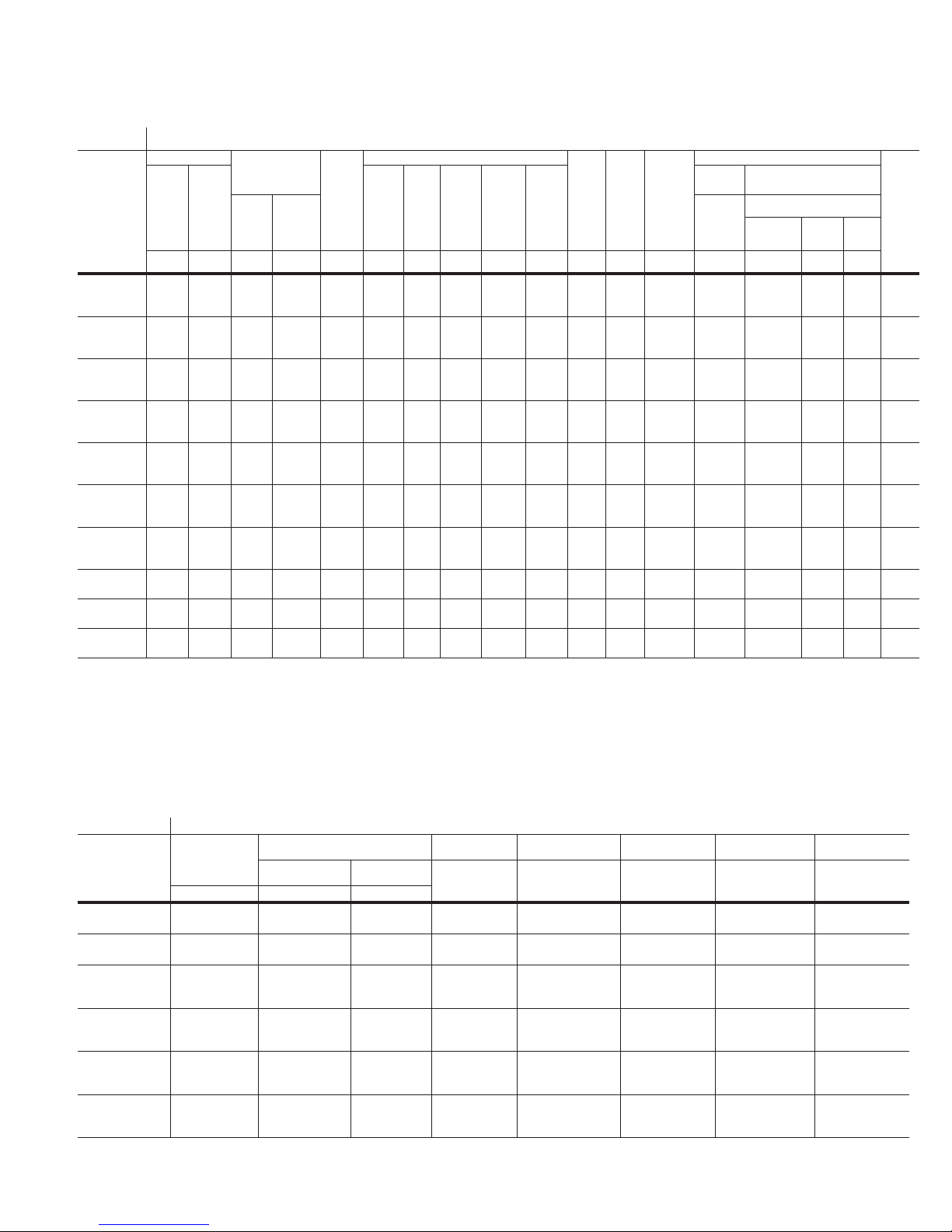
Table 3. (ANSI Standards) type VCP-WC extra capability vacuum circuit breaker 5-27 kV rated symmetrical current basis.
Identification Rated voltage
Circuit
breaker
type
50 VCP-W
40C
50 VCP-W
50C
75 VCP-W
50C
150 VCP-W
25C
150 VCP-W
40C
150 VCP-W
50C
150 VCP-W
63C
270 VCP-W
25C
270 VCP-W
32C
270 VCP-W
40C
a
3 cycles
b
Close & latch current for 1200 A Type 150 VCP-W 25C is proven at 15 kV. For sealed interrupters at high altitudes, switching voltage is not de-rated.
c
For higher RRRV contact Eaton for more information.
d
Breaker tested to 2700 A single bank switching for momentary load ( Thermal derating must consider harmonic content of current waveform).
e
Breaker tested to 1270 A back-to-back switching for momentary load (Thermal derating must consider harmonic conten t of current w aveform)
f
Capacitor switching ratings are proven at 15 kV. For se aled interr upters at high altitudes, switching voltage is not de-rated.
g
1 second
h
2 second
i
C37.04 a-2003 class C2 @ 15 kV
Voltage Insulation level
Max.
voltage
V
KV rms kV rms kV peak A rms
Voltage
range
factor
K
withstand test
Power
Lighten-
freq-
ing
uency
impulse
(1 min .)
1.2x50us
Continuous
curre nt
at
60 Hz
5.95 1 24 75 12 00
2000
3000
5.95 1 24 75 12 00
2000
3000
10.3 1 42 95 120 0
2000
3000
17. 5 1 42 95 120 0
2000
3000
17. 5 1 42 95 120 0
2000
3000
17. 5 1 42 95 120 0
2000
3000
17. 5 1 42 95 120 0
2000
3000
27 1 60 125 1200
1600
27 1 60 125 1200
1600
27 1 60 125 1200
1600
Short circuit current Inter-
Sym
% DC
Asym.
Closing
inter -
comp onent
(Idc)
inter rupting
(It)
rupting
at V
(Isc)
kA rms
total % k A rms
Short -
&
time
latch ing
curre nt
capa -
for 3
bility
sec.
kA
peak k A rms Cyc les Sec. kV / µs A rms A rms
40 75. 58 139 40 3 2 0.9
50 57
50 57
25 50
57
52
57
52
75
75
64
139 50 3 2 0.9
64
62
64
139 50 3 2 0.9
64
62
31
b
97
25 3 2 0.95
36
36
40 75 58 13 9 40 3 2 0.9
50 57
63 61
57
52
61
61
64
139 50 3 2 0.9
64
62
83
175 63 3 2 1.0 7
83
83
rupting
time
a
Max.
permis
sible
tripping
delay
Transient
recovery
voltage
(RRRV)
c
0.9
0.8
0.9
0.8
0.9
0.8
0.9
0.8
0.9
0.8
0.9
0.8
1.07
1.07
Capac itor switchin g ratings Mech-
General
purpose
Isolated
shunt
capacitor
bank
current
630 d
630 d
250
630 d
630 d
250
Definite purpose
Back to b ack capacito r
switching
Capacitor
bank
current
630 e
1000 e
—
630 e
1000 e
—
630 e
1000 e
—
600 f
1000 ef
—
630 ef
1000 ef
d
—
630 ef
1000 ef
d
—
200,1600i
200,1600i
200,1600
Inrush
current
kA
peak kHz
15
18
—
15
18
—
15
18
—
20
18
—
15
18
—
15
18
—
7.7
7.7
i
7.7
25 75 36 85 25 h3 2 1.1 400 20 4.2 2,500
31.5 57 40 97 32 g3 1 1.1 400 20 4.2 2,500
40 50 49 10 4 40 g3 1 1.1 400 20 4.2 2,500
Inrush
frequency
3.5
2.7
—
3.5
2.7
—
3.5
2.7
—
3.5
2.7
—
3.5
2.7
—
3.5
2.7
—
465
465
465
anical
endurance
Noload
operation s
10,000
10,000
5,000
10,000
10,000
5,000
10,000
10,000
5,000
10,000
10,000
5,000
10,000
10,000
5,000
10,000
10,000
5,000
10,000
10,000
10,000
Table 4. (IEC-56 Standardsa) type VCP-W vacuum circuit breaker through 17.5 kV rated symmetrical current basis.
Identification Rated values
Circuit
breaker type
36VCPW-ND25
36VCPW-ND32
72VCPW-ND25
72VCPW-ND32
36VCP-W25
36VCP-W32
36VCP-W40
72VCP-W25
72VCP-W32
72VCP-W40
120VCP-W25
120VCP-W32
120VCP-W40
175VCP-W25
175VCP-W32
175VCP-W40
a
Interrupting time is 3 cycles at 50/60 Hz. Rated operating sequence 0-3 min- CO-3 min-CO.
Voltage class Insulation level Normal
Power
frequency
3.6
3.6
7.2
7.2
3.6
3.6
3.6
7.2
7.2
7.2
12.0
12.0
12.0
17. 5
17. 5
17. 5
10
10
20
20
10
10
10
20
20
20
28
28
28
38
38
38
Impulse
withstand
40
40
60
60
40
40
40
60
60
60
75
75
75
95
95
95
current
Amperes kA rms kA rm s kV peak AmpereskV rms kV rms kV peak
630, 1250
630, 1250
630, 1250
630, 1250
630, 1250, 2000
1250, 2000
1250, 2000
630, 1250, 2000
1250, 2000
1250, 2000
630, 1250, 2000
1250, 2000
1250, 2000
1250, 2000
1250, 2000
1250, 2000
Short circuit
breaking current
25
31.5
25
31.5
25
31.5
40
25
31.5
40
25
31.5
40
25
31.5
40
3 second short
time current
25
31.5
25
31.5
25
31.5
40
25
31.5
40
25
31.5
40
25
31.5
40
EATON www.eaton.com
Short circuit
making current
63
79
63
79
63
79
100
63
79
100
63
79
100
63
79
100
Cable charging
breaking amps
25
25
25
25
25
25
25
25
25
25
25
25
25
31.5
31.5
31.5
9
Instruction Booklet IB131006EN
Effective March 2019
operation, and maintenance of type
Instructions for installation,
VCP-W vacuum circuit breakers
Table 5. (ANSI Standardsa) type VCP-W (K = 1) vacuum circuit breaker through 15 kV rated symmetrical current basis (standard
ratings).
Identification Rate d values
Circuit
breaker
type
Nominal
voltage
class
kV kV rms kV rms kV peak Amperes kA r ms Ms Seconds kV rms kA peak kA rms
Voltage Insulation level Current Inter-
Max.
voltage
E
50VCP-W 25 4.16 4.76 1.0 19 60 120 0
50VCP-W 40 4.16 4.76 1.0 19 60 120 0
50VCP-W 50 4.16 4.76 1.0 19 60 120 0
50VCP-W 63 4.16 4.76 1.0 19 60 120 0
75VCP-W 40 7.2 8.25 1.0 36 95 1200
75VCP-W 50 7.2 15 1.0 36 60 120 0
150VCP-W 25 13.8 15 1. 0 36 95 120 0
150VCP-W 40 13.8 15 1. 0 36 95 120 0
150VCP-W 50 13.8 15 1. 0 36 95 120 0
150VCP-W 63 13.8 1.0 36 95 120 0
a
All circuit breakers are tested to 60 Hz; however, they can also be applied at 50 Hz with no derating.
b
Consult the Consulting Application Guide CA08104001E sections 1 and 5 for further information.
c
Also 3-second shor t time current carrying capability.
a
Voltage
range
factor
K
Withstand test
voltage
b
Power
frequency
(1 min .)
Impulse
Continuous
current
at 60 Hz
2000
3000
2000
3000
2000
3000
2000
3000
2000
3000
2000
3000
2000
3000
2000
3000
2000
3000
2000
3000
Short
circuit
current
(at rated
max. kV )
c
I
rupting
time
Permissible
tripping
delay
Y
Max.
voltage
divided
by K
E/K
Current values
Closing &
latching
capability
2.6 K
times
rated
short
25 3 or 5 2 4.76 65 39
40 3 or 5 2 4.76 10 4 62
50 3 or 5 2 4.76 130 78
63 3 or 5 2 4.76 164 98
40 3 or 5 2 11. 5 104 62
50 3 or 5 2 11. 5 130 78
25 3 or 5 2 15. 0 65 39
40 3 or 5 2 15.0 104 62
50 3 or 5 2 15.0 130 78
63 3 or 5 2 15.0 164 98
Closing &
latching
capability
momentary
1.6 K
times rated
short
circuit
current
Table 6. (ANSI Standardsa) type VCP-WXC circuit breaker through 15 kV rated symmetrical current basis (standard ratings).
See Figure 23 for control schemes and diagram that apply to this breaker. This breaker dif fers from the standard breaker with the addition of a third motor cut-off switch and
addition of two wires.
Identification Rated voltage
Circuit
breaker
type
150 VCP-WXC 6317. 5 1 42 95 120 0
a
All circuit breakers are tested to 60 Hz; however, they can also be applied at 50 Hz with no derating.
b
Optional interrupting time of 3 cycles is available.
c
For higher RRRV contact Eaton for more information.
10
Voltage Insulation level
Max.
voltage
V
kV rms kV r ms kV peak A rm s
Voltage
range
factor
K
withstand test
Power
Lighten-
freq-
ing
uency
impulse
(1 min .)
1.2x50us
Continuous
curre nt
at
60 Hz
2000
3000
EATON www.eaton.com
Short circuit current Inter-
Sym
% DC
Asym.
inter -
comp -
rupting
onent
at V
(Idc)
(Isc)
kA rms
total % k A rms
63 61
61
61
Closing
inter -
&
rupting
latch ing
(It)
capa bility
kA
peak k A rms Cycl es Sec. kV / µs A rms A rms
83
175s 63 5 2 1.07
83
83
Short time
curre nt
for 3
sec.
rupting
time
b
Max.
permis
sible
tripping
delay
Transient
recovery
voltage
(RRRV)
c
1.07
1.07
Capac itor switchin g ratings Mech-
General
Definite purpose
purpose
Isolated
Back to b ack capacito r
shunt
switching
capaci-
capacitor
tor
bank
bank
current
current
200,1600(9)
200,1600(9)
200,1600(9)
Inrush
Inrush
current
frequency
kA
peak kHz
7.7
465
7.7
465
7.7
465
anical
endurance
Noload
operation s
10,000
10,000
5,000
Instructions for installation,
operation, and maintenance of type
VCP-W vacuum circuit breakers
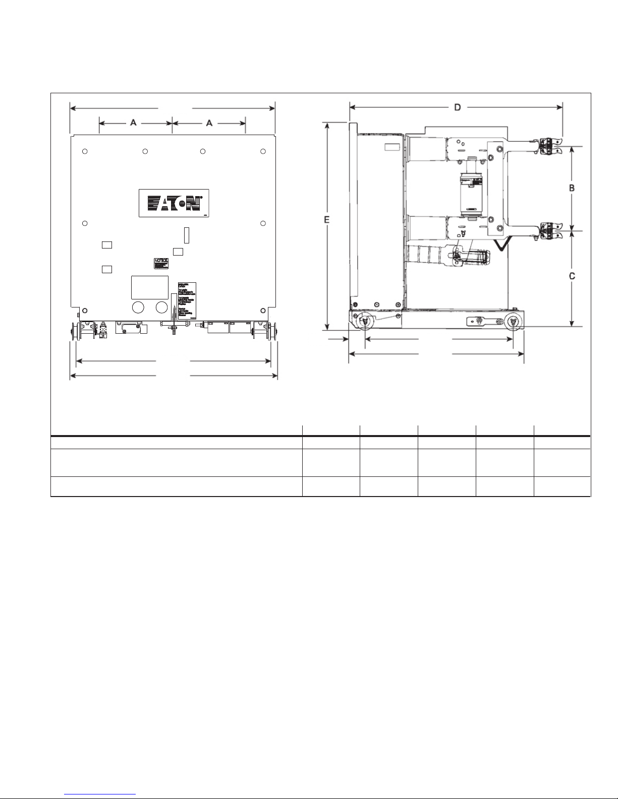
1.4 Outlines and dimensions
29.13
(739.90)
Instruction Booklet IB131006EN
Effective March 2019
2.25
27.80
(706.12)
29.56
(750.82)
Breaker Identification A B C D E
240 VCP-W, 270 VCP-W & 270 VCP-WC 10 (254.0 0) 14 (355.60) 16.25 (412.75) 34.80 (883.92) 35.22 (894.59)
50/350, 50/350C, 150/1000, 150/1000C, 150/63, 3000A VCP-W, VCPW-SE,VCP-
WC & VCP-W K=1>=50 kA
Except those immediately below
All Other VCP-W,VCPW-SE & VCP-W K=1<=40 kA
including 50/25C & 150/25C, 1200 A
(57.15)
10 (254.0 0) 12 (304.80) 13.63 (346.20) 29.94 (760.48) 31.44 (79 8.5 8)
10 (254.0 0) 12 (304.80) 13.63 (346.20) 29.81 (757.17) 29.44 (747.7 8)
20.88
(530.35)
24.63
(625.60)
Figure 1. Type VCP-W (K = 1 & MVA), VCPW-SE, and VCP-WC circuit breaker outlines and dimensions in inches (mm).
EATON www.eaton.com
11

Instruction Booklet IB131006EN
Effective March 2019
7.00
(177.80)
21.38
(543.05)
7.00
(177.80)
Instructions for installation,
operation, and maintenance of type
VCP-W vacuum circuit breakers
3.69
(93.73)
29.44
(747.78)
2.25
(57.15)
19.44
(493.78)
21.96
(557.78)
30.38
(771.65)
12.00
(304.80)
13.63
(346.202)
20.88
(530.35)
24.63
(625.60)
Figure 2. Type VCPW-ND circuit breaker outlines and dimensions in inches (mm).
12
EATON www.eaton.com

Instructions for installation,
operation, and maintenance of type
VCP-W vacuum circuit breakers
Instruction Booklet IB131006EN
Effective March 2019
2. Safe practices
2.1 Recommendations
Type VCP-W vacuum circuit breaker elements are equipped with high
speed, high energy operating mechanisms. They are designed with
several built-in interlocks and safety features to provide safe and
proper operating sequences.
m WARNING
TO PROTECT THE PERSONNEL ASSOCIATED WITH INSTALLATION,
OPERATION, AND MAINTENANCE OF THESE CIRCUIT BREAKER ELEMENTS,
THE FOLLOWING PRACTICES MUST BE FOLLOWED.
•
Only qualified persons as defined in section 6.2.1 and with
respect to the local electric code, who are familiar with the
installation and maintenance of medium voltage circuits and
equipment, should be permitted to work on these circuit breaker
elements.
•
Read these instructions carefully before attempting any installation, operation or maintenance of these breakers.
•
Always remove the breakers from the enclosure before performing any maintenance. Failure to do so could result in electrical
shock leading to death, severe personal injury, or property
damage.
•
BE EXTREMELY CAREFUL while the circuit breaker is on the
extension rails. Use provided rail clamps to firmly hold the circuit
breaker on the extension rails while performing such activities
as charging, closing, and tripping. Carelessness could cause the
circuit breaker to fall from the rails resulting in personal injury to
those in the area.
•
Do not work on a closed breaker or a breaker with closing springs
charged. The closing spring should be discharged and the main
contacts open before working on the breaker. Failure to do so
could result in cutting or crushing injuries.
•
Do not use a circuit breaker by itself as the sole means of
isolating a high voltage circuit. Remove the breaker to the
DISCONNECT position and follow good lockout and tagging rules,
as well as all applicable codes, regulations, and work rules.
•
Do not leave the breaker in an intermediate position in the cell.
Always have the breaker either in the TEST or CONNECTED
position. Failure to do so could result in a flash over and possible
death, personal injury, or property damage.
•
Always remove the maintenance tool from the breaker after charging the closing springs.
•
Breakers are equipped with safety interlocks. Do not defeat
them. This may result in death, bodily injury, or equipment
damage.
3. Receiving, handling, and storage
3.1 General
Type VCP-W vacuum circuit breaker elements are subjected to
complete factory production tests and inspection before being
packed. They are shipped in packages designed to provide
maximum protection to the equipment during shipment and storage
and at the same time to provide convenient handling. Tools, such as
the maintenance tool, are shipped separately.
3.2 Receiving
If the circuit breaker element is not to be used immediately but is
to be placed in storage, maximum protection can be obtained by
keeping it packed as shipped.
Upon receipt of the equipment, inspect the containers for any signs
of damage or rough handling. Open the containers carefully to avoid
any damage to the contents. Use a nail puller rather than a crow bar
when required. When opening the containers, be careful to save
any loose items or hardware that may be otherwise discarded with
the packing material. Check the contents of each package against
the packing list.
Examine the circuit breaker element for any signs of shipping
damage such as broken, missing, or loose hardware, damaged or
deformed insulation, and other components. File claims immediately with the carrier if damage or loss is detected and notify the
nearest Eaton office.
3.3 Handling
m CAUTION
DO NOT USE ANY LIFTING DEVICE AS A PLATFORM FOR PERFORMING
MAINTENANCE, REPAIR, OR ADJUSTMENT OF THE BREAKER OR FOR
OPENING, CLOSING THE CONTACTS OR CHARGING THE SPRINGS. THE
CIRCUIT BREAKER ELEMENT MAY SLIP OR FALL CAUSING SEVERE
PERSONAL INJURY. ALWAYS PERFORM MAINTENANCE, REPAIR, AND
ADJUSTMENTS ON A SOLID WORK SURFACE CAPABLE OF SUPPORTING
THE BREAKER ELEMENT.
When a breaker element is ready for installation, a lifting yoke in
conjunction with an overhead lifter or portable floor lifter can be used
to move a breaker element. When a breaker element is to be lifted,
position the lifting yoke over the breaker element and insert lifters
into the breaker element side openings with the lifting hole toward
the interrupters. Once the lifting yoke is securely seated in the
holes, the breaker element can be carefully lifted and moved. Also,
a breaker lift pan in conjunction with the portable floor lifter can be
used to create a breaker lifter. The breaker can be placed or rolled
onto the lift pan with the conductors arms pointing away from the
lifter (see IB022015EN for more details).
3.4 Storage
If the circuit breaker element is to be placed in storage, maximum
protection can be obtained by keeping it packed as shipped. Before
placing it in storage, checks should be made to make sure that the
breaker element is free from shipping damage and is in satisfactory
operating condition.
The circuit breaker element is shipped with its contacts open and
closing springs discharged. The indicators on the front panel should
confirm this. Insert the maintenance tool in the manual charge
socket opening (Figure 5). Charge the closing springs by pumping
the handle up and down approximately 38 times until a crisp metallic
“click” is heard. This indicates that the closing springs are charged
and is shown by the closing spring “charged” (yellow) indicator.
Remove the maintenance tool. Operate the push-to-close button.
The breaker element will close as shown by the breaker contacts
“closed” (red) indicator. Operate the push-to-open button. The
breaker element will trip as shown by the breaker contacts “open”
(green) indicator. After completing this initial check, leave the closing
springs “discharged” and breaker contacts “open”.
EATON www.eaton.com
13

Instruction Booklet IB131006EN
Effective March 2019
Instructions for installation,
operation, and maintenance of type
VCP-W vacuum circuit breakers
Outdoor storage of the breaker element is NOT recommended.
If unavoidable, the outdoor location must be well drained and a
temporary shelter from sun, rain, snow, corrosive fumes, dirt, falling
objects, and excessive moisture must be provided. Containers
should be arranged to permit free circulation of air on all sides
and temporary heaters should be used to minimize condensation.
Moisture can cause rusting of metal parts and deterioration of high
voltage insulation. A heat level of approximately 400 watts for each
100 cubic feet (2.83 cubic meters) of volume is recommended with
the heaters distributed uniformly throughout the structure near the
floor.
Indoor storage should be in a building with sufficient heat and air
circulation to prevent condensation. If the building is not heated, the
same general rule for heat as for outdoor storage should be applied.
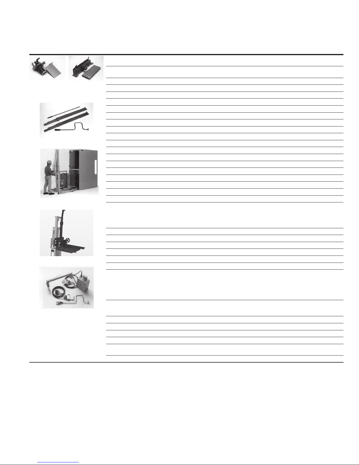
3.5 Tools and accessories
Tools and accessories, both standard and optional, are available for
use with the circuit breaker element (Figure 3). If not specified
accessories can be used for 36 in. wide and 26 in. wide breakers.
Spin-free levering-in crank: Used to crank breaker between
DISCONNECT, TEST, and CONNECTED positions.
Extension rails: Permits breaker to be withdrawn from its compartment.
Rail clamps: Used to secure breaker to extension rails.
Lifting yoke: Used to lift breaker.
Manual charging handle: Used to charge closing springs manually.
Portable lifter: Used to lift breaker to or from extended rails.
Breaker lift pan: This accessory enables the breaker to be lifted
from the ground to any height cell without the extension rails. It
consists of a portable lifter and a MV breaker lift pan.
•
Portable lifter;
•
MV breaker lift pan with short extension rail kit for 36”or 26” wide
breaker.
Drawout ramp: Used to insert or withdraw breaker from lower
compartment without portable lifter.
Docking transport dolly: Used to insert or withdraw breaker from
lower compartment without portable lifter or move breaker from one
location to another.
Electrical levering-in device:
BPI pan assembly:
Integral Motorized Racking (MR2) used to electrically move
breaker between DISCONNECT/TEST, or DISCONNECT, TEST, and
CONNECTED positions is available. Specified by description as
opposed to a style number.
If the external electric levering-in device which mounts to the door or
pan assembly is used, then the breaker can be moved between the
DISCONNECT and CONNECTED positions.
The process of levering the breaker from the DISCONNECT to the
TEST position would need to be performed manually (approximately
6 turns).
Non-BPI pan assembly:
Used to electrically move the breaker between DISCONNECT/TEST
and CONNECTED positions.
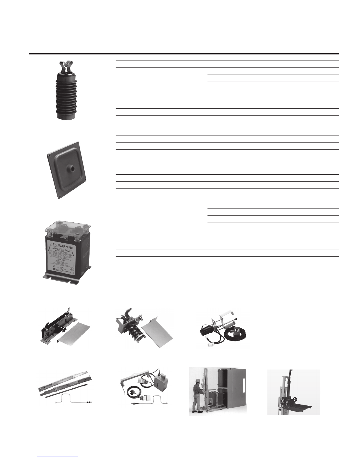
Truck operated cell (TOC) switch: Indicates when breaker is in the
CONNECT position. Furnished with standard push on wire terminals. Optional ring tongue terminals are available.
Mechanism operated cell (MOC) switch: Provides additional
normally open and closed contacts for when control and protection
scheme exceeds the available auxiliary contacts in the breaker.
Furnished with standard push on wire terminals. Optional ring
tongue terminals are available.
This feature is available in two different configurations:
1.) Functions in both the TEST and CONNECT positions, or
2.) Functions only in the CONNECT position.
Eaton strongly recommends use of the TEST and CONNECT position
configuration.
Test jumper: Used to operate breaker electrically while breaker is on
extension rails or transport dolly.
Test cabinet: Used to provide power to operate breaker outside its
compartment for the purpose of testing functionality.
Key provisions with positional interlock: This enables locking of
the levering-in cage when the breaker is in the TEST position with a
padlock or keyed cylinder lock.
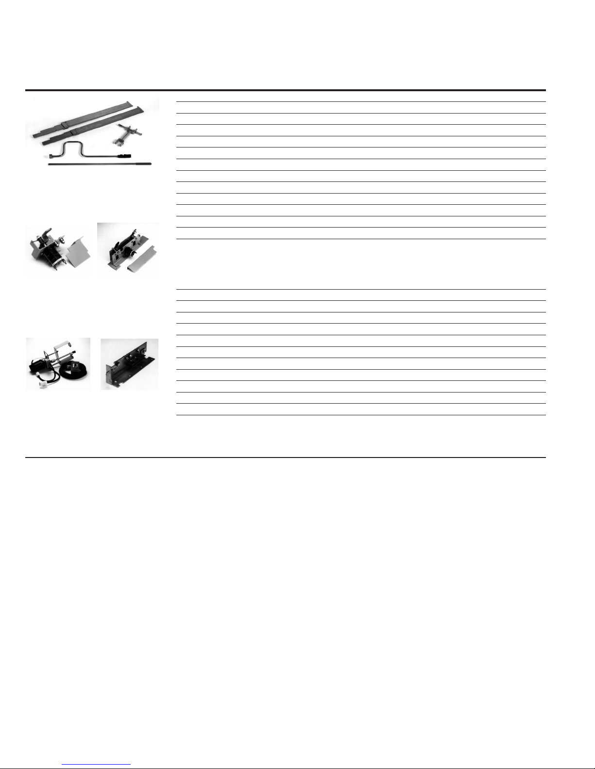
Wheel conversion kit (MG & TD only): Due to how the manual
ground and test device is designed this is the best direct roll-in
wheel kit to use.
Wheel conversion kit for direct roll-in: This wheel kit can be used
to convert a standard breaker or electrical ground and test device to
a direct roll-in version.
Conversion kit ROF to non-ROF: This kit is used to convert a direct
roll-in cell to a non direct roll-in cell. It provides the teeter totter
feature that prevents removing a breaker from the breaker cell when
the extension rails or MV breaker lift pan are not in place. Also,
the short ramp feature in the front of each rail would need to be
removed.
Conversion kit non-ROF to ROF: This kit is used to convert a nondirect roll-in cell to a direct roll-in cell. It provides the ramp feature
that goes on the end of each rail to help guide the steel wheels on
the side of the breaker up onto the rail rolling surface. This is only
to be used in the lower switchgear cells that are level with the floor.
The teeter totter feature that keeps the breaker from being rolled out
of the cell would need to be removed.
Secondary conversion kit: This kit converts an automatic secondary
in a BPI pan assembly to a manual enabled automatic secondary.
When the release lever is raised above the stop feature the secondaries will slide forward to automatically connect, see section 8.2 for
more details.
Closed door racking guide: This feature can be added to the front
of the BPI pan assembly to provide a guide for the manual leveringin tool when the switchgear door is closed to guide the levering-in
crank socket onto the levering-in drive screw nut.
14
EATON www.eaton.com
Instructions for installation,
operation, and maintenance of type
VCP-W vacuum circuit breakers
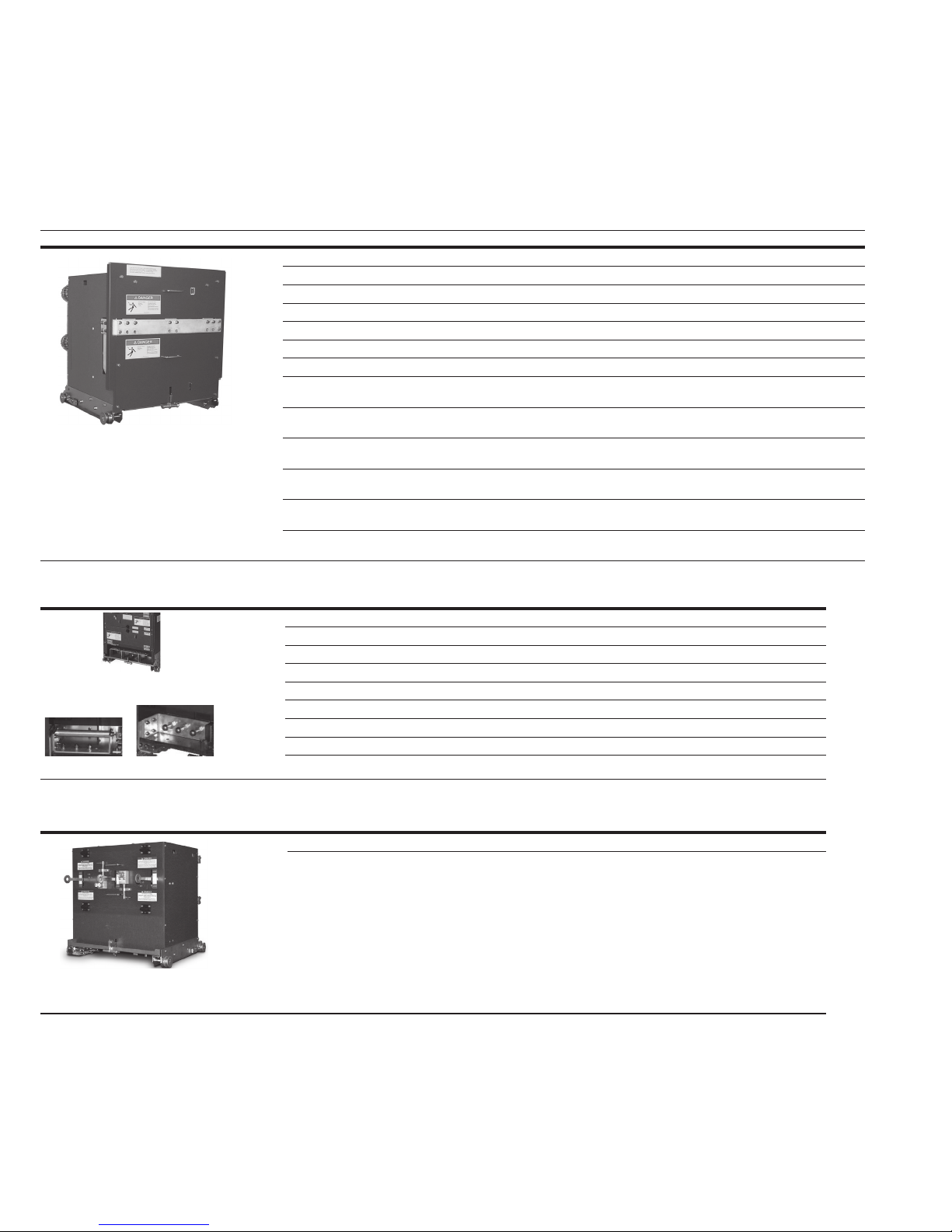
Table 7. Accessories for 36-inch wide breaker compartments for 29-inch frame breaker.
Description Style number
TOC (truck-operated cell) switch
4A/5B contacts
TOC (truck-operated cell) switch
4A/ 5B contacts ring-tongue terminals
5A/5B TOC switch
Standard set of accessories
Portable lifter and lift pan
Optional accessories include (clockwise):
lifting yoke, test cabinet, spin-free levering
crank, and test jumper
5A/5B MOC switch
Portable lifter
MOC (mechanism-operated cell) switch
5A/4B contacts (test and connect) 1C20007G12
5A/4B contacts (connect only) 1C20007G13
10A/8B contacts (test and connect) 1C20007G14
10A/8B contacts (connect only) 1C2 0007G15
15A/12B contacts (test and connect) 1C20007G16
15A/12B contacts (connect only) 1C20007G17
5A/4B contacts (test and connect) ring-tongue terminals 1C20007G28
5A/4B contacts (connect only) ring-tongue terminals 1C20007G29
10A/8B contacts (test and connect) ring-tongue terminals 1C20007G30
10A/8B contacts (connect only) ring-tongue terminals 1C20007G31
15A/12B contacts (test and connect) ring-tongue terminals 1C20007G32
15A/12B contacts (connect only) ring-tongue terminals 1C20007G33
Spin-free levering-in crank with clutch 701B601G11
Extension rails (right and left, one set) 7813C41G03
Set of rail clamps 6511C8 3G11
Lifting yoke 69 1C607G 11
Manual charging handle 8064A02G11
Standard set of accessories
Spin-free levering-in crank with clutch
Extension rails (right and left, one set)
Manual charging handle
Set of rail clamps
Portable lifter (26-/36-inch conver tible) 1C19086 H01
MV breaker lift pan 1C20220G01
Drawout ramp 1C14163G08
Docking transport dolly 6510C71G21
Electrical levering-in device 1A30257G01
Test jumper 6526C23G11
Test cabinet
Any DC close and any trip
AC or DC close and DC trip
120 Vac close and capacitor trip
240 Vac close and capacitor trip
AC or DC charge, DC close and trip
Key provisions with positional Interlock
This allows for key locking the levering-in cage
when the breaker is in the TEST position.
Wheel conversion kit (MG & TD only) 68C5010G41
Wheel conversion kit for direct roll-in 68C5010G 42
Conversion kit ROF to NON-ROF 1C19779G101
Conversion kit NON- ROF to ROF 1C19779G102
Secondary conversion kit: to convert automatic
secondary to manual operation
Closed door racking guide 1C2 0339G02
Instruction Booklet IB131006EN
Effective March 2019
1C20006G12
1C20006G15
1A30136G02
8346A28G21
8346A28G22
8346A28G23
8346A28G60
8346A28G24
6510C48G22
1C2 0335G01
EATON www.eaton.com
15
Instruction Booklet IB131006EN
Effective March 2019
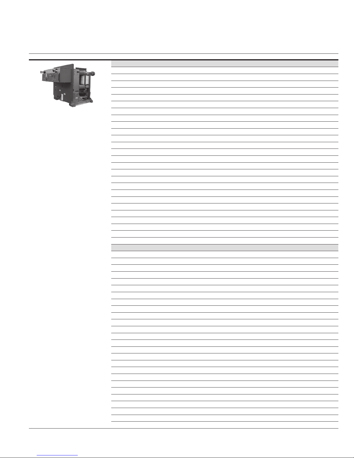
Table 8. Narrow design accessories for 26-inch-wide breaker compartments.
Description Style number
TOC (truck-operated cell) switch 4A/3B contacts 7797C20G01
MOC (mechanism-operated cell) switch
4A/3B contacts (test and connect) 7797C24G02
4A/3B contacts (connect only) 7797C24G03
8A/6B contacts (test and connect) 7797C24G04
8A/6B contacts (connect only) 7797C24G05
Set of ND accessories
ND 4A/3B
TOC switch
Electric levering-in
device
ND 4A/3B
MOC switch
Padlock/key
interlock
12A/9B contacts (test and connect) 7797C24G06
Spin-free levering-in crank with clutch 701B601G11
Primar y contact spanner wrench 502A850G01
Extension rails (right and left, one set) 7813C41G03
Set of rail clamps 6511C8 3G12
Lifting yoke 691C607G02
Manual charging handle 8064A02G11
Set of ND accessories
Spin-free levering-in crank with clutch
Primar y contact spanner wrench
Extension rails (right and left, one set)
Manual charging handle
Set of rail clamps
Portable lifter (26-/36-inch conver tible) 1C19086 H01
MV breaker lift pan and short extension rail kit 1C19086 G01
Drawout ramp 1C14163G01
Docking transport dolly 6510C71G02
Electrical levering-in device 1A30257G01
Tes t jumpe r 1C15331G0 1
Test cabinets
Any DC close and any trip 8346A28G41
AC or DC close and DC trip 8346A28G42
120 Vac close and capacitor trip 8346A28G43
240 Vac close and capacitor trip 8346A28G60
Padlock/key provisions with positional interlock
Includes the padlock assembly plus a
positional interlock. This allows for key
locking the levering-in cage when the
breaker is locked in the DISCONNECT position
Instructions for installation,
operation, and maintenance of type
VCP-W vacuum circuit breakers
1A30136G04
6510C48G01
16
EATON www.eaton.com
Instructions for installation,
operation, and maintenance of type
VCP-W vacuum circuit breakers
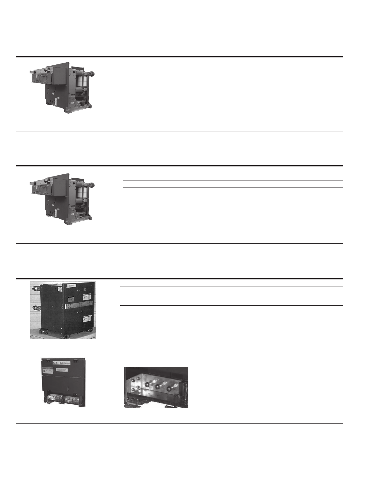
Table 9. 27 kV VCP-W accessories.
Description Style number
TOC (truck operated cell) switch 5A/5B contacts 6510C49G12
TOC (direct roll-in) 691C568G06
MOC (mechanism operated cell) switch 5A/4B contacts (test and connect) 6529C58G02
Spin-free levering-in crank 701B601G11
Standard levering-in crank 701B601G12
Epoxy stand-off insulator
Epoxy cable support
Extension rails (right and left—one set) 7813C41G03
Set of rail clamps 6511C8 3G11
Lifting yoke 69 1C607G 11
Manual charging handle 8064A02G11
Standard set of 27 kV accessories Levering-in crank with clutch manual
Portable lifter 1C19086 H01
MV breaker lift pan 1C20220G01
Drawout ramp 1C14163G02
Docking transport dolly 6510C71G11
Electrical levering-in device (120 Vac) 1A30257G01
Test cabinet Any DC close and any trip 8346A28G21
Tes t jumpe r 6526C23G11
120 Vac capacitor trip device 3A39175G01
240 Vac capacitor trip device 3A39175G02
27 kV epoxy cable support 7799C52H01
8.25 inch epoxy stand-off insulator 1A34286H01
Instruction Booklet IB131006EN
Effective March 2019
5A/4B contacts (connect only) 6529C58G03
10A/8B contacts (test and connect) 6529C58G04
10A/8B contacts (connect only) 6529C58G05
15A/12B contacts (test and connect) 6529C58G06
15A/12B contacts (connect only) 6529C58G07
1A30136G02
charging handle
Wheel kit (for direct roll-in) 68C 5010G42
AC or DC close and DC trip 8346A28G22
120 Vac close and capacitor trip 8346A28G23
240 Vac close and capacitor trip 8346A28G60
Capacitor trip device
5A/5B TOC switch
Standard accessories include
(clockwise): Left and right removable
extension rails, manual charging
handle, and levering crank
Optional accessories include
(clockwise): lifting yoke, test
cabinet, spin-free levering crank,
5A/5B MOC switch
and test jumper
Electrical levering-in device
Portable lifter
Portable lifter and lift pan
EATON www.eaton.com
17
Instruction Booklet IB131006EN
Effective March 2019
operation, and maintenance of type
Instructions for installation,
VCP-W vacuum circuit breakers
Ground and test device (G&TD) accessories: Eaton offers a broad spectrum of manual and electrical G&TDs. All of the manual G&TDs
provide access to all the line and load terminals to enable phase checking. Also, they provide the ability to verify operation of the voltage
sensing equipment against a live source while verifying that the other connection does not have any voltage present prior to applying the
grounds. The simple electrical G&TDs only provide access to line or load terminals. One of the designs provides the ability to perform cable
testing as well as grounding the desired circuit.
Table 10. Simple manual ground and test devices—bus bar type.
25 and 40 kA 50 kA 63 kA
Description Style number Style number Style number
Simple manual ground
and test device
Upper and lower terminals 1200 A (26” narrow design) 4A35130G01
Upper and lower terminals 1200/2000 A 66A5092G42 66A5092G02 66A5092G12
Upper and lower terminals 3000 A 66A5092G43 66A5092G03 66A5092G13
Upper terminals only 1200/2000 A 66A5092G44 66A5092G04 66A5092G14
Lower terminals only 1200/2000 A 66A5092G45 66A5092G05 66A5092G15
Upper terminals only 3000 A 66A5092G46 66A5092G06 66A5092G16
Lower terminals only 30 00 A 66A5092G47 66A5092G07 66A5092G17
Upper and lower terminals
1200/2000 A with ROF wheels installed
Upper and lower terminals
3000 A with ROF wheels installed
Upper terminals only
1200/2000 A with ROF wheels installed
Lower terminals only
1200/2000 A with ROF wheels installed
Upper terminals only
3000 A with ROF wheels installed
Lower terminals only
3000 A with ROF wheels installed
66A5092G82 66A5092G62 66A5092G72
66A5092G83 66A5092G63 66A5092G73
66A5092G84 66A5092G64 66A5092G74
66A5092G85 66A5092G65 66A5092G75
66A5092G86 66A5092G66 66A5092G76
66A5092G87 66A5092G67 66A5092G77
— —
Table 11. 15 kV VCP-W simple manual ground and test device—“bail” and “ball” type a .
Description Style number
Bail 1200/2000 A upper/lower 66A5201G01
Bail 3000 A upper/lower 66A5201G02
Ball 1200/2000 A upper/lower 66A5291G01
Bail type manual ground
and test device
Bail connector Ball connector
Ball 3000 A upper/lower 66A5291G02
Bail 1200/2000 A upper/lower with ROF wheels installed 66A5201G11
Bail 3000 A upper/lower with ROF wheels installed 66A5201G12
Ball 1200/2000 A upper/lower with ROF wheels installed 66A5291G11
Ball 3000 A upper/lower with ROF wheels installed 66A5291G12
a Cables are not provided
Table 12. Complex manual (selectable) ground and test device.
Description Style number
1200/2000/3000 A, 50 kA with ROF 94G7092G712
1200/2000/3000 A, 50 kA (standard, non-ROF) 94G7091G711
Ground and test device
18
EATON www.eaton.com
Instructions for installation,
operation, and maintenance of type
VCP-W vacuum circuit breakers
Table 13. Simple electrically operated ground and test device.
Description Style number Style number Style number
Without roll-on-floor wheels (ROF) factory installed
Upper terminal
1200/2000 A, 4 8 Vdc 66A5302G75 — —
1200/2000 A, 125 Vdc or 120 Vac 66A5302G76 — —
1200/2000 A, 250 Vdc or 240 Vac 66A5302G77 — —
1200/2000 A, 4 8 Vdc — 66A5302G02 —
1200/2000 A, 125 Vdc or 120 Vac — 66A5302G03 —
Simple electrically operated ground
and test device
1200/2000 A, 250 Vdc or 240 Vac — 66A5302G04 —
3000 A, 48 Vdc — 66A5302G05 —
3000 A, 125 Vdc or 120 Vac — 66A5302G06 —
3000 A, 250 Vdc or 240 Vac — 66A5302G07 —
1200/2000/3000 A, 48 Vdc — — 66A5302G12
1200/2000/3000 A, 125 Vdc or 120 Vac — — 66A5302G13
1200/2000/3000 A, 250 Vdc or 240 Vac — — 66A5302G14
Lower terminal
1200/2000 A, 4 8 Vdc 66A5302G85 — —
1200/2000 A, 125 Vdc or 120 Vac 66A5302G86 — —
1200/2000 A, 250 Vdc or 240 Vac 66A5302G87 — —
1200/2000 A, 4 8 Vdc — 66A5302G22 —
1200/2000 A, 125 Vdc or 120 Vac — 66A5302G23 —
1200/2000 A, 250 Vdc or 240 Vac — 66A5302G24 —
3000 A, 48 Vdc — 66A5302G25 —
3000 A, 125 Vdc or 120 Vac — 66A5302G26 —
3000 A, 250 Vdc or 240 Vac — 66A5302G27 —
1200/2000/3000 A, 48 Vdc — — 66A5302G32
1200/2000/3000 A, 125 Vdc or 120 Vac — — 66A5302G33
1200/2000/3000 A, 250 Vdc or 240 Vac — — 66A5302G34
With roll-on-floor wheels (ROF) factory installed
Upper terminal
1200/2000 A, 4 8 Vdc with ROF 66A5302G53 — —
1200/2000 A, 125 Vdc or 120 Vac with ROF 66A5302G54 — —
1200/2000 A, 250 Vdc or 240 Vac with ROF 66A5302G55 — —
1200/2000 A, 4 8 Vdc with ROF — 66A5302G35 —
1200/2000 A, 125 Vdc or 120 Vac with ROF — 66A5302G36 —
1200/2000 A, 250 Vdc or 240 Vac with ROF — 66A5302G37 —
3000 A, 48 Vdc with ROF — 66A5302G38 —
3000 A, 125 Vdc or 120 Vac with ROF — 66A5302G39 —
3000 A, 250 Vdc or 240 Vac with ROF — 66A5302G40 —
1200/2000/3000 A, 4 8 Vdc with ROF — — 66A5302G41
1200/2000/3000 A, 125 Vdc or 120 Vac with ROF — — 66A5302G42
1200/2000/3000 A, 250 Vdc or 240 Vac with ROF — — 66A5302G43
Lower terminal
1200/2000 A, 4 8 Vdc with ROF 66A5302G57 — —
1200/2000 A, 125 Vdc or 120 Vac with ROF 66A5302G58 — —
1200/2000 A, 250 Vdc or 240 Vac with ROF 66A5302G59 — —
1200/2000 A, 4 8 Vdc with ROF — 66A5302G44 —
1200/2000 A, 125 Vdc or 120 Vac with ROF — 66A5302G45 —
1200/2000 A, 250 Vdc or 240 Vac with ROF — 66A5302G46 —
3000 A, 48 Vdc with ROF — 66A5302G47 —
3000 A, 125 Vdc or 120 Vac with ROF — 66A5302G48 —
3000 A, 250 Vdc or 240 Vac with ROF — 66A5302G49 —
1200/2000/3000 A, 4 8 Vdc with ROF — — 66A5302G50
1200/2000/3000 A, 125 Vdc or 120 Vac with ROF — — 66A5302G51
1200/2000/3000 A, 250 Vdc or 240 Vac with ROF — — 66A5302G52
Instruction Booklet IB131006EN
Effective March 2019
25 and 40 kA 50 kA 63 kA
EATON www.eaton.com
19
Instruction Booklet IB131006EN
Effective March 2019
operation, and maintenance of type
VCP-W vacuum circuit breakers
Table 14. Simple electrically operated ground and test device for VCP-W without key interlocks.
Description Style number
Lower terminal
1200/2000 A, 125 Vdc or 120 Vac, 50 kA with ROF 66A5312G45
Electrically operated ground and test device
Note: These units are also available as direct-roll-on-the-floor products via a separately purchased wheel kit.
Table 15. Simple electrically operated ground and test device for VCP-WXC.
Description Style number
Upper terminal
1200/2000/3000 A, 125 Vdc or 120 Vac, 63 kA 66A5302G83
Lower terminal
1200/2000/3000 A, 125 Vdc or 120 Vac, 63 kA 66A5302G93
Instructions for installation,
Electrically operated ground and test device
Note: These units are also available as direct-roll-on-the-floor products via a separately purchased wheel kit.
Table 16. 27 kV manual ground and test device.
Description Style number
1200/2000 A, bus bar type —top and bottom studs 1C 94 354G01
1200/2000 A, bus bar type —top and bottom studs with factory
installed wheel kit
1200/2000 A, ball type—top and bottom studs 66A5296G01
1200/2000 A, ball type—top and bottom studs with factory installed
wheel kit
27 kV simple manual ground and
test device—bus bar type
1C94 35 4G11
66A5296G11
Ball type
20
EATON www.eaton.com
Ball connector

Instructions for installation,
operation, and maintenance of type
VCP-W vacuum circuit breakers
Instruction Booklet IB131006EN
Effective March 2019
Table 17. Dummy elements
Description
a.
Style
number
5 kV, 1200 A (up to 50 kA) 691C605G03
5 kV, 2000 A (up to 50 kA) 691C605G04
5 kV, 3000 A (up to 63 kA) 691C605G05
15 kV, 1200 A (up to 50 kA) 691C605G06
15 kV, 2000 A (up to 5 0 kA) 691C605G07
15 kV, 3000 A (up to 6 3 kA)
a
Dummy elements applicable for breakers rated VCP-W MVA, VCP-W K = 1, and VCP-WSE.
b
Dummy element also applicable for VCP-WXC breaker.
b
691C605G08
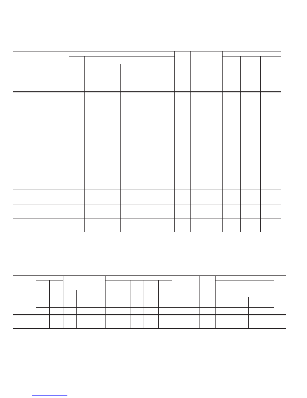
3.6 Type VCP-W vacuum circuit breaker element weights
(Tables 18, 19, and 20).
Table 18. VCP-W ANSI rated breaker weightsa.
Rating Amperes Lbs. (kg)
50VCPW-ND250 12 00 345 (157)
50VCP-W250
50VCPW-SE250
50VCP-W350
50VCPW-SE350
75VCP-W500
75VCPW-SE500
150VCP-W500
150VCPW-SE500
150VCP-W750
150VCPW-SE750
150VCP-W1000
150VCPW-SE1000
150VCP-W1500(63)
150VCPW-SE1500(63)
270VCP-W750(16) 600
270 VCP-W1000(22) 600
270 VCP-W1250(25) 600
270 VCP-W1600(32) 120 0
270VCP-W2000(40) 120 0
a
Does not include shipping carton.
1200
2000
3000
1200
2000
3000
1200
2000
3000
1200
2000
3000
1200
2000
3000
1200
2000
3000
1200
2000
3000
1200
2000
1200
2000
1200
2000
2000
2000
35 0 (159)
410 (186)
525 (238)
460 (209)
490 (222)
525 (238)
375 (170)
410 (186)
525 (238)
350 (159)
410 (186)
525 (238)
350 (159)
410 (186)
525 (238)
460 (209)
490 (222)
525 (238)
525 (238)
530 (241)
550 (250)
460 (209)
480 (218)
500 (227)
460 (209)
480 (218)
500 (227)
460 (209)
480 (218)
500 (227)
545 (245)
560 (252)
545 (245)
560 (252)
EATON www.eaton.com
21

Instruction Booklet IB131006EN
Effective March 2019
Instructions for installation,
operation, and maintenance of type
VCP-W vacuum circuit breakers
Table 19. VCP-W IEC rated breaker weightsa.
Normal
Rating
current
amperes Lb s. (kg)
36VCPW-ND25 630
1250
36VCPW-ND32 630
1250
72VCPW-ND25 630
1250
72VCPW-ND32 630
1250
36VCP-W25 630
1250
2000
36VCP-W32 1250
2000
36VCP-W40 1250
2000
72VCP-W25 630
1250
2000
72VCP-W32 1250
2000
72VCP-W40 1250
2000
120VCP-W25 630
1250
2000
120VCP-W32 1250
2000
120VCP-W40 1250
2000
175VCP-W25 630
1250
2000
175VCP-W32 125 0
2000
175VCP-W40 125 0
2000
240 VCP-W1 6 630
1250
2000
240 VCP-W20 630
1250
2000
40 VCP-W25 630
1250
2000
a
Does not include shipping carton.
350 (159)
35 0 (159)
350 (159)
35 0 (159)
350 (159)
35 0 (159)
350 (159)
35 0 (159)
350 (159)
350 (159)
410 (186)
350 (159)
410 (186)
375 (170)
410 (186)
350 (159)
350 (159)
410 (186)
350 (159)
410 (186)
375 (170)
410 (186)
350 (159)
350 (159)
410 (186)
350 (159)
410 (186)
375 (170)
410 (186)
350 (159)
350 (159)
410 (186)
375 (170)
410 (186)
375 (170)
410 (186)
462 (210)
484 (220)
506 (230)
462 (210)
484 (220)
506 (230)
462 (210)
484 (220)
506 (230)
Table 20. VCP-W (K = 1) breaker weightsa.
Rating Amperes Lbs. (kg)
150 VCP-W 25 1200
2000
3000
150 VCP-W 40 1200
2000
3000
150 VCP-W 50 1200
2000
3000
150 VCP-W 63 1200
2000
3000
75 VCP-W 40 1200
2000
3000
75 VCP-W 50 1200
2000
3000
50 VCP-W 25 1200
2000
3000
50 VCP-W 40 1200
2000
3000
50 VCP-W 50 1200
2000
3000
50 VCP-W 63 1200
2000
3000
a
Does not include shipping carton.
35 0 (159)
375 (170)
500 (227))
375 (170)
375 (170)
500 (227)
48 0 (218)
490 (222)
500 (227)
460 (209)
490 (222)
525 (238)
375 (170)
375 (170)
500 (227)
48 0 (218)
490 (222)
525 (227)
35 0 (159)
375 (170)
500 (227)
375 (170)
375 (170)
500 (227)
48 0 (218)
490 (222)
500 (227)
460 (209)
490 (222)
525 (238)
22
EATON www.eaton.com
 Loading...