

Eaton 150VCP-W500, 50VCP-W250, 150VCP-W750, 150VCP-W1000, 50 VCP-W 40C Installation, Operation And Maintenance Manual
...
I.B. 32-255-1G
Effective 12/02 Supersedes I.B. 32-255-1F dated January 2000
Cutler-Hammer
Instructions for Installation, Operation and Maintenance
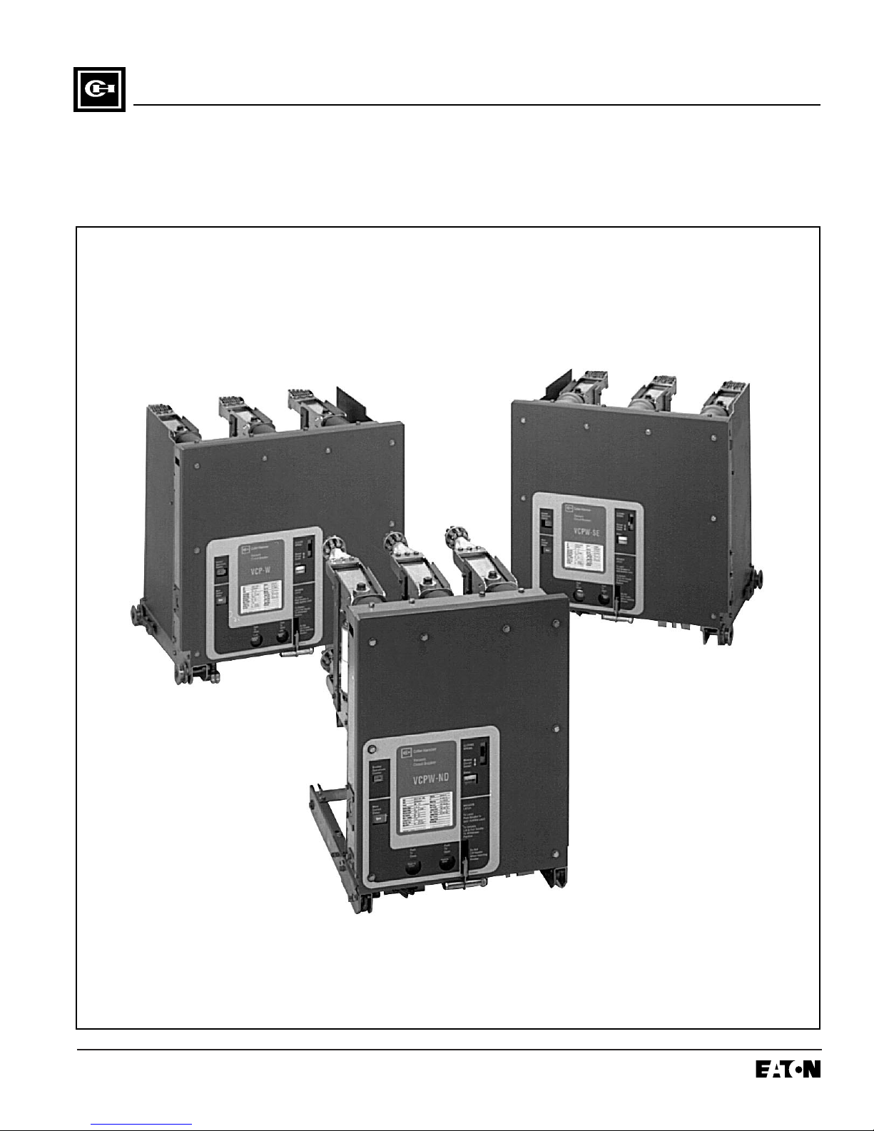
of Type VCP-W Vacuum Circuit Breakers


I.B. 32-255-1G
Page iii
Effective 12/02
All possible contingencies which may arise during installation, operation or maintenance, and all details and
variations of this equipment do not purport to be covered by these instructions. If further information is
desired by purchaser regarding his particular installation, operation or maintenance of particular equipment,
contact a Cutler-Hammer representative.
IMPROPERLY INSTALLING OR MAINTAINING
THESE PRODUCTS CAN RESULT IN DEATH, SERIOUS PERSONAL INJURY, OR PROPERTY DAMAGE.
READ AND UNDERSTAND THESE INSTRUCTIONS
BEFORE ATTEMPTING ANY UNPACKING, ASSEMBLY, OPERATION OR MAINTENANCE OF THE CIRCUIT BREAKERS.
INSTALLATION OR MAINTENANCE SHOULD BE
ATTEMPTED ONLY BY QUALIFIED PERSONNEL.
THIS INSTRUCTION BOOK SHOULD NOT BE CONSIDERED ALL INCLUSIVE REGARDING INSTALLATION OR MAINTENANCE PROCEDURES. IF FURTHER INFORMATION IS REQUIRED, YOU SHOULD
CONTACT CUTLER-HAMMER.
THE CIRCUIT BREAKER ELEMENTS DESCRIBED IN
THIS BOOK ARE DESIGNED AND TESTED TO
OPERATE WITHIN THEIR NAMEPLATE RATINGS.
OPERATION OUTSIDE OF THESE RATINGS MAY
CAUSE THE EQUIPMENT TO FAIL, RESULTING IN
DEATH, BODILY INJURY AND PROPERTY DAMAGE.
ALL SAFETY CODES, SAFETY STANDARDS
AND/OR REGULATIONS AS THEY MAY BE
APPLIED TO THIS TYPE OF EQUIPMENT MUST BE
STRICTLY ADHERED TO.
THESE CIRCUIT BREAKER ELEMENTS ARE
DESIGNED TO BE INSTALLED PURSUANT TO THE
AMERICAN NATIONAL STANDARDS INSTITUTE
(ANSI). SERIOUS INJURY, INCLUDING DEATH, CAN
RESULT FROM FAILURE TO FOLLOW THE PROCEDURES OUTLINED IN THIS MANUAL. THESE CIRCUIT BREAKER ELEMENTS ARE SOLD PURSUANT
TO A NON-STANDARD PURCHASING AGREEMENT
WHICH LIMITS THE LIABILITY OF THE MANUFACTURER.
!
WARNING
!
WARNING

I.B. 32-255-1G
Page iv
Effective 12/02
TABLE OF CONTENTS
PAGE
SECTION 1 INTRODUCTION
1-1 Preliminary Comments and Safety Precautions..................................................................................................1
1-1.1 Warranty and Liability Information..........................................................................................................1
1-1.2 Safety Precautions .................................................................................................................................1
1-2 General Information.............................................................................................................................................1
1-3 Type VCP-W Vacuum Circuit Breaker Element Ratings (Tables 1.1, 1.2, 1.3 and 1.4)......................................3
1-4 Outlines and Dimensions ....................................................................................................................................5
SECTION 2 SAFE PRACTICES
2-1 Recommendations ..............................................................................................................................................7
SECTION 3 RECEIVING, HANDLING AND STORAGE
3-1 General ...............................................................................................................................................................8
3-2 Receiving.............................................................................................................................................................8
3-3 Handling..............................................................................................................................................................8
3-4 Storage ...............................................................................................................................................................8
3-5 Tools and Accessories........................................................................................................................................9
3-6 Type VCP-W Vacuum Circuit Breaker Element Weights (Tables 3.1 and 3.2)...................................................9
SECTION 4 INITIAL INSPECTION AND INSTALLATION
4-1 Introduction........................................................................................................................................................16
4-2 Manual Operation Check...................................................................................................................................16
4-3 Vacuum Interrupter Integrity..............................................................................................................................16
4-4 Insulation...........................................................................................................................................................16
4-5 Contact Erosion and Wipe.................................................................................................................................16
4-6 Primary Circuit Resistance................................................................................................................................16
4-7 Nameplate.........................................................................................................................................................16
4-8 Electrical Operation Check................................................................................................................................17
4-8.1 Circuit Breaker Insertion and Removal.................................................................................................17
4-8.2 Operation Check Performance.............................................................................................................19
4-9 Circuit Breaker/Structure Interfacing.................................................................................................................20
4-9.1 Interface Interlocks/Interfacing Check..................................................................................................20
SECTION 5 DESCRIPTION AND OPERATION
5-1 Introduction........................................................................................................................................................22
5-2 Interrupter Assembly.........................................................................................................................................22
5-2.1 Vacuum Interrupter...............................................................................................................................22
5-2.2 Contact Erosion Indication ...................................................................................................................23
5-2.3 “T” Cutout Loading Spring Indicator .....................................................................................................23
5-2.4 Contact Wipe and Stroke .....................................................................................................................23
5-2.5 Phase Barriers......................................................................................................................................23

I.B. 32-255-1G
Page v
Effective 12/02
PAGE
5-3 Stored Energy Mechanism................................................................................................................................24
5-3.1 Operation of Stored Energy Mechanism ..............................................................................................24
5-3.2 Charging...............................................................................................................................................27
5-3.3 Closing Operation.................................................................................................................................27
5-3.4 Tripping Operation................................................................................................................................27
5-3.5 Trip Free Operation..............................................................................................................................27
5-4 Control Schemes...............................................................................................................................................27
5-4.1 Timing...................................................................................................................................................29
5-4.2 Secondary Disconnects........................................................................................................................29
5-4.3 Undervoltage Trip Device.....................................................................................................................29
5-5 Interlocks and Interfacing..................................................................................................................................31
5-6 Levering Mechanism.........................................................................................................................................31
5-7 Operations Counter...........................................................................................................................................31
5-8 Ground Contact.................................................................................................................................................31
5-9 MOC and TOC Switch Operations....................................................................................................................31
SECTION 6 INSPECTION, MAINTENANCE AND TROUBLESHOOTING
6-1 Introduction........................................................................................................................................................32
6-2 Frequency of Inspection and Maintenance .......................................................................................................32
6-2.1 Qualified Personnel..............................................................................................................................32
6-2.2 General Torque Guidelines ..................................................................................................................32
6-3 Inspection and Maintenance Procedures..........................................................................................................34
6-4 Vacuum Interrupter Integrity Test......................................................................................................................35
6-5 Contact Erosion and Wipe.................................................................................................................................36
6-6 Insulation...........................................................................................................................................................36
6-7 Insulation Integrity Check..................................................................................................................................37
6-8 Primary Circuit Resistance Check.....................................................................................................................38
6-9 Mechanism Check.............................................................................................................................................38
6-9.1 CloSure
TM
Test .....................................................................................................................................38
6-10 Lubrication.........................................................................................................................................................42
6-11 Troubleshooting Chart.......................................................................................................................................43
SECTION 7 RENEWAL PARTS
7-1 General .............................................................................................................................................................46
7-1.1 Ordering Instructions............................................................................................................................46

I.B. 32-255-1G
Page vi
Effective 12/02
FIGURES
Figure Title Page
1-1 Type VCP-W and Type VCPW-SE Circuit Breaker Outlines and Dimensions in inches...........................5
1-2 Type VCPW-ND Circuit Breaker Outlines and Dimensions in inches........................................................6
3-1 Typical VCP-W Tools and Accessories...................................................................................................11
3-2 Typical Front View VCP-W Vacuum Circuit Breaker Element.................................................................12
3-3 Typical VCP-W Vacuum Circuit Breaker Element with Front Cover Removed .......................................13
3-4 Typical Rear View VCP-W Vacuum Circuit Breaker Element..................................................................14
3-5 Typical VCP-W Vacuum Circuit Breaker Element Escutcheon ...............................................................15
4-1 Type VCP-W Circuit Breaker Manual Charging Handle in Use...............................................................16
4-2 Typical VCP-W Circuit Breaker Compartment.........................................................................................18
4-3 Engaging Extension Rails in a Lower Circuit Breaker Compartment.......................................................19
4-4 Typical VCP-W Circuit Breaker Bottom View ..........................................................................................19
4-5 Pulling Secondary Disconnect Cage to Engage Secondaries in TEST Position.....................................20
4-6 Engaging Levering-In Crank....................................................................................................................20
5-1 Typical VCP-W Rear View Showing Vacuum Interrupters and Current Carrying System.......................22
5-2 Graphic Representation of Arc Interruption.............................................................................................23
5-3 Closing Cam and Trip Linkage ................................................................................................................25
5-4 Charging Schematic ................................................................................................................................26
5-5 Typical VCP-W DC and AC Control Schemes.........................................................................................28
5-6 Undervoltage Trip Device Configuration..................................................................................................30
6-1 Lubrication Points....................................................................................................................................33
6-1b 150 VCP-W 63 63kA Pole Unit................................................................................................................33
6-2 Vacuum Interrupter Showing Contact Erosion Indicator with Breaker Open...........................................36
6-3 Vacuum Interrupter Showing Contact Erosion Indicator with Breaker Closed.........................................36
6-4 Wipe Indication Procedure ......................................................................................................................37
6-5 Status Indicators......................................................................................................................................38
6-6 Starting Tape at Bottom of Cam..............................................................................................................39
6-7 Wrapping Tape Up Aroung Cam .............................................................................................................39
6-8 Attaching Tape Around to Back of Cam ..................................................................................................39
6-9 Attaching CloSure
TM
Test Tool at Hole “A” ..............................................................................................39
6-10 Attaching CloSureTMTest Tool at HP.......................................................................................................40
6-11 Manually Charging Closing Strips............................................................................................................40
6-12 Manually Closing Circuit Breaker with Marker in Hole “C”.......................................................................40
6-13 Top View of CAM and Marker Interface...................................................................................................40
6-14 Move Marker 15
o
to Right.......................................................................................................................40
6-15 Move Marker 15
o
to Left .........................................................................................................................41
6-16 Remove Marker Masking Tape from Cam...............................................................................................41
6-17 Place Tape on Right Side Panel of Breaker............................................................................................41
6-18 Illustrative Testing Tape Sample .............................................................................................................41
6-19 Front View of CloSureTMTool Showing Mounting/Testing Hole Locations..............................................41
6-20 Typical Circuit Breaker Font View with CloSureTMTool Attached............................................................42

I.B. 32-255-1G
Page vii
Effective 12/02
TABLES
Table Title Page
1.1 Type VCP-W Vacuum Circuit Breaker Through 15 kV Rated Symmetrical Current Basis........................2
1.2 Type VCP-W Vacuum Circuit Breaker 27 kV Rated Symmetrical Current Basis ......................................3
1.3 Type VCP-W Extra Capability Vacuum Circuit Breaker 5-15 kV Rated Symmetrical Current Basis ........3
1.4 Type VCP-W Generator Vacuum Circuit Breaker 5-15 kV Rated Symmetrical Current Basis .................4
1.5 Type VCP-W Generator Vacuum Circuit Breaker Through 17.5 kV Rated Symmetrical Current Basis ...4
1.6 Type VCP-W Generator Vacuum Circuit Breaker Through 17.5 kV Rated Symmetrical Current Basis....4
3.1 Type VCP-W ANSI Breaker Weights.........................................................................................................9
3.2 VCP-W IEC Rated Breaker Weights........................................................................................................10
5.1 VCP-W Circuit Breaker Barrier Configurations........................................................................................24
5.2 Circuit Breaker Timing .............................................................................................................................29
6.1 Torque Guidelines ...................................................................................................................................33
6.2 Test Voltage.............................................................................................................................................35
6.3 Typical Resistance Measurements..........................................................................................................38
6.4 Closure
TM
Tool Mounting/Testing Locations by Circuit Breaker Type......................................................42
7.1 Recommended Renewal Parts for ANSI Rated Breakers .......................................................................46
7.2 Recommended Renewal Parts for IEC Rated Breakers..........................................................................53

I.B. 32-255-1G
Page viii
Effective 12/02
I.B. 32-255-1G
Page 1
Effective 12/02
SECTION 1: INTRODUCTION
1-1 PRELIMINARY COMMENTS AND SAFETY PRECAUTIONS
This technical document is intended to cover most
aspects associated with the installation, operation and
maintenance of Type VCP-W, VCPW-SE, and VCPWND Vacuum Circuit Breakers. It is provided as a guide
for authorized and qualified personnel only. Please refer
to the specific WARNING and CAUTION in Paragraph
1-1.2 before proceeding past Section 1. If further information is required by the purchaser regarding a particular installation, application or maintenance activity, a
Cutler-Hammer representative should be contacted.
1-1.1 WARRANTY AND LIABILITY INFORMATION
NO WARRANTIES, EXPRESSED OR IMPLIED,
INCLUDING WARRANTIES OF FITNESS FOR A PARTICULAR PURPOSE OF MERCHANTABILITY, OR
WARRANTIES ARISING FROM COURSE OF DEALING OR USAGE OF TRADE, ARE MADE REGARDING
THE INFORMATION, RECOMMENDATIONS AND
DESCRIPTIONS CONTAINED HEREIN. In no event will
Cutler-Hammer be responsible to the purchaser or user
in contract, in tort (including negligence), strict liability or
otherwise for any special, indirect, incidental or consequential damage or loss whatsoever, including but not
limited to damage or loss of use of equipment, plant or
power system, cost of capital, loss of power, additional
expenses in the use of existing power facilities, or
claims against the purchaser or user by its customers
resulting from the use of the information and descriptions contained herein.
1-1.2 SAFETY PRECAUTIONS
All safety codes, safety standards and/or regulations
must be strictly observed in the installation, operation
and maintenance of this device.
THE WARNINGS AND CAUTIONS INCLUDED AS
PART OF THE PROCEDURAL STEPS IN THIS DOCUMENT ARE FOR PERSONNEL SAFETY AND PROTECTION OF EQUIPMENT FROM DAMAGE. AN
EXAMPLE OF A TYPICAL WARNING LABEL HEADING IS SHOWN ABOVE IN REVERSE TYPE TO
FAMILIARIZE PERSONNEL WITH THE STYLE OF
PRESENTATION. THIS WILL HELP TO INSURE
THAT PERSONNEL ARE ALERT TO WARNINGS,
WHICH MAY APPEAR THROUGHOUT THE DOCUMENT. IN ADDITION, CAUTIONS ARE ALL UPPER
CASE AND BOLDFACE AS SHOWN BELOW.
COMPLETELY READ AND UNDERSTAND THE
MATERIAL PRESENTED IN THIS DOCUMENT
BEFORE ATTEMPTING INSTALLATION, OPERATION
OR APPLICATION OF THE EQUIPMENT. IN ADDITION, ONLY QUALIFIED PERSONS SHOULD BE
PERMITTED TO PERFORM ANY WORK ASSOCIATED WITH THE EQUIPMENT. ANY WIRING INSTRUCTIONS PRESENTED IN THIS DOCUMENT MUST BE
FOLLOWED PRECISELY. FAILURE TO DO SO
COULD CAUSE PERMANENT EQUIPMENT DAMAGE.
1-2 GENERAL INFORMATION
The purpose of this book is to provide instructions for
unpacking, storage, use, operation and maintenance of
Type VCP-W, VCPW-SE, and VCPW-ND Vacuum Circuit
Breakers. These circuit breakers are horizontal drawout
type removable interrupting elements designed for use
in VacClad-W Metal-Clad Switchgear and appropriate
VCP-W modules. They provide reliable control and protection for medium voltage electrical equipment and circuits. All VCP-W circuit breaker elements are designed
to ANSI Standards for reliable performance, ease of
handling and simplified maintenance. In addition, VCPW circuit breakers are tested to both ANSI and IEC
Standards for application around the world.
The VCPW-SE circuit breaker element is a VCP-W circuit breaker designed specifically for special environment applications and operating conditions through 27
kV. The VCPW-ND circuit breaker element is a narrow
design VCP-W circuit breaker designed specifically for
use in 5 kV applications where floor space requirements
would not allow the industry standard 36 inch wide
switchgear. From this point on, all circuit breaker elements will be referred to as Type VCP-W unless the reference is specific to a particular design.
SATISFACTORY PERFORMANCE OF THESE CIRCUIT
BREAKER ELEMENTS IS CONTINGENT UPON PROPER APPLICATION, CORRECT INSTALLATION AND
ADEQUATE MAINTENANCE. THIS INSTRUCTION
!
CAUTION
!
WARNING
!
WARNING

I.B. 32-255-1G
Page 2
Effective 12/02
BOOK MUST BE CAREFULLY READ AND FOLLOWED IN ORDER TO OBTAIN OPTIMUM PERFORMANCE FOR LONG USEFUL LIFE OF THE CIRCUIT
BREAKER ELEMENTS.
THE CIRCUIT BREAKER ELEMENTS DESCRIBED IN
THIS BOOK ARE DESIGNED AND TESTED TO OPER-
ATE WITHIN THEIR NAMEPLATE RATINGS. OPERATION OUTSIDE OF THESE RATINGS MAY CAUSE
THE EQUIPMENT TO FAIL, RESULTING IN DEATH,
BODILY INJURY AND PROPERTY DAMAGE.
ALL SAFETY CODES, SAFETY STANDARDS AND/OR
REGULATIONS AS THEY MAY BE APPLIED TO THIS
TYPE OF EQUIPMENT MUST BE STRICTLY ADHERED
TO.
!
WARNING
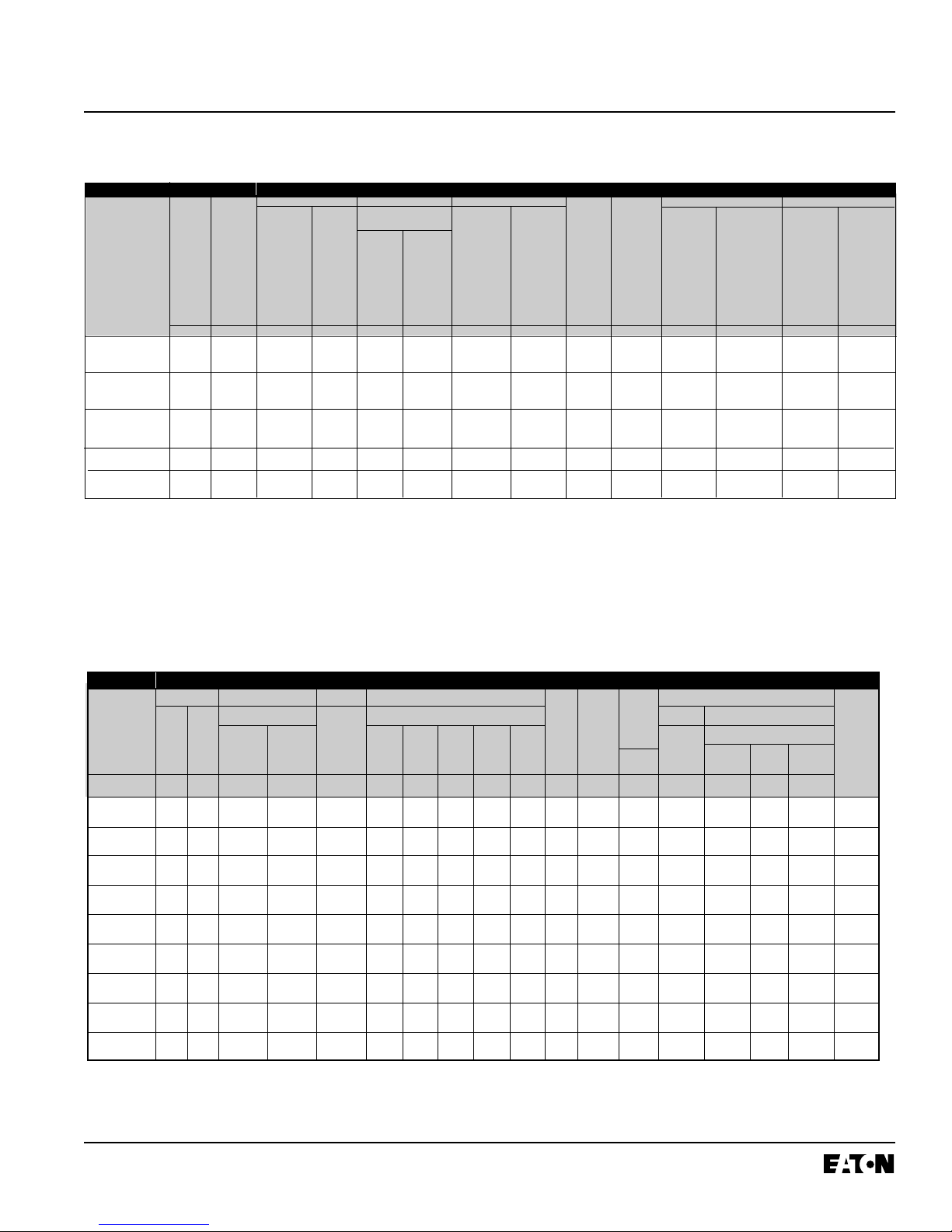
1-3 TYPE VCP-W VACUUM CIRCUIT BREAKER ELEMENT RATINGS (TABLES 1.1, 1.2, 1.3, 1.4, 1.5 AND 1.6)
Table 1.1 (ANSI Standards➀) Type VCP-W Vacuum Circuit Breaker Through 15 kV Rated Symmetrical Current Basis
➀
Applicable ANSI Standards C37.04-1979, C37.09-1979 and C37.06-1987.
Operating Duty Cycle CO-15 seconds-CO. Operating Time Values: Opening
30-45 ms, Closing 45-60 ms and Reclosing 18 cycles (300 rms).
➁
Non-standard circuit breakers with High Close and Latch (momentary)
rating for special applications.
➂
Consult Application Data 32-265 for further information.
➃
Optional interrupting time of 3 cycles is available.
➄
Also 3-second short time current carrying capability.
Identification Rated Values
Circuit Nominal Nominal Voltage Insulation Level Current Inter- Permis- Maximum Current Values
Breaker Voltage 3-Phase Maximum Voltage Withstand Test Continuous Short rupting sible Voltage Maximum Closing Closing
Type Class MVA Voltage Range Voltage Current Circuit Time
➃
Tripping Divided Symmetrical and and
Class Factor
➂
at 60 Hz Current Delay By K Interrupting Latching Latching
(at Rated Capability Capability Capability
Max. kV) Momentary
Power Impulse K Times 2.7 K 1.6 K
Frequency Rated Short Times Times
(1 Min.) Circuit Rated Rated
Current
➂➄
Short Short
Circuit Circuit
Current Current
E K I Y E/K
kV MVA kV rms kV rms kV Peak Amperes kA rms Cycles Seconds kV rms kA rms kA Peak kA rms
50VCPW-ND250 4.16 250 4.76 1.24 19 60 1200 29 5 2 3.85 36 97 58
50VCP-W250 4.16 250 4.76 1.24 19 60 1200 29 5 2 3.85 36 97 58
2000 132
➁
78
➁
3000
50VCP-W350 4.16 350 4.76 1.19 19 60 1200 41 5 2 4.0 49 132 78
2000
3000
75VCP-W500 7.2 500 8.25 1.25 36 95 1200 33 5 2 6.6 41 111 66
2000
3000
150VCP-W500 13.8 500 15 1.30 36 95 1200 18 5 2 11.5 23 62 37
2000 97
➁
58
➁
3000
150VCP-W750 13.8 750 15 1.30 36 95 1200 28 5 2 11.5 36 97 58
2000 130
➁
77
➁
3000
150VCP-W1000 13.8 1000 15 1.30 36 95 1200 37 5 2 11.5 48 130 77
2000
3000
150VCP-W1500
(63)
13.8 1500 15 1.00 36 95 1200 63 5 2 15.0 63 170 101
2000
3000
I.B. 32-255-1G
Page 3
Effective 12/02
Table 1.2 (ANSI Standards➀) Type VCP-W Vacuum Circuit Breaker 27 kV Rated Symmetrical Current Basis
Identification Rated Values
Circuit Nominal Nominal Voltage Insulation Level Current Inter- Permis- Transient Recovery Voltage Current Values
Breaker Voltage 3-Phase Maximum Voltage Withstand Test Continuous Short rupting sible E
2
t
2
Closing Capacitor
Type Class MVA Voltage
➁
Range Voltage Current Circuit Time ➃Tripping Rise and Switching
Class Factor
➂
at 60 Hz Current
➄
Delay Time Latching Cable
Capability Charging
Power Impulse 3 Second 2.7 K Times
Frequency Short Time Rated
(1 Min.)
Current
Short
Carrying
Circuit
Capability Current
EK I Y
kV MVA kV rms kV rms kV Peak Amperes kA rms Cycles Seconds kV Peak µs kA Peak Amperes
270VCP-W750
(16)
27 750 27 1.0 60 125 600 16 5 2 51 105 43 31.5
1200
2000
270VCP-W1000
(22)
27 1000 27 1.0 60 125 600 22 5 2 51 105 60 31.5
1200
2000
270VCP-W1250
(25)
27 1250 27 1.0 60 125 600 25 5 2 51 105 68 31.5
1200
2000
270VCP-W1600
(32)
27 1600 27 1.0 60 125 1200 31.5 5 2 51 105 85 31.5
2000
270VCP-W2000
(40)
27 2000 27 1.0 60 125 1200 40 5 2 51 105 106 31.5
2000
➀
CESI tested to applicable ANSI Standards C37.04 - 1979, C37.09 - 1979, and
C37.06 - 199X. Consult Cutler-Hammer for CESI reports on file. Operating duty
cycle CO-15 seconds-CO. Operating time values: opening 33-55 ms, closing
50-60 ms and reclosing 18 cycles (300 ms).
➁
Testing at 28.5 kV.
➂
K=1.0, therefore E = E/K and I = KI. Consult Application Data 32-265 for further
information.
➃
Optional interrupting time of 3 cycles is available.
➄
Also maximum interrupting rating.
5.95
5.95
10.3
17.5
17.5
17.5
27
27
27
1
1
1
1
1
1
1
1
1
24
24
42
42
42
42
60
60
60
75
75
95
95
95
95
125
125
125
40
50
50
25
40
50
25
31.5
40
75
57
57
52
57
57
52
50
75
75
75
57
57
52
75
57
50
58
64
64
62
64
64
62
31
36
36
58
64
64
62
36
40
49
139
139
139
97 (2)
139
139
85
97
104
40
50
50
25
40
50
25 (8)
32 (7)
40 (7)
50
50
50
50
50
50
50
50
50
2
2
2
2
2
2
2
1
1
0.9
0.9
0.8
0.9
0.9
0.8
0.9
0.9
0.8
0.95
0.9
0.8
0.9
0.9
0.8
0.9
0.9
0.8
1.1
1.1
1.1
15
18
—
15
18
—
15
18
—
20
18
—
15
18
—
15
18
—
20
20
20
3.5
2.7
—
3.5
2.7
—
3.5
2.7
—
3.5
2.7
—
3.5
2.7
—
3.5
2.7
—
4.2
4.2
4.2
Max
Voltage
V
Voltage
Range
Factor
K
Voltage
Power
Frequency
(1 Min.)
Lightening
Impulse
1.2x50us
Withstand Test
Insulation Level
Continuous
Current at
60 Hz
Sym.
Inter-
rupting
at V (Isc)
% dc
compo-
nent
(Idc)
Asym.
Inter-
rupting
(It)
Closing
&
Latching
Capability
Short-
Time
Current
for
3 sec.
Short-Circuit Current
Current
Inter-
rupting
Time
(1)
Maximum
Permis-
sible
Tripping
Delay
Transient
Recovery
Voltage
(RRRV)
(3)
Isolated
Shunt
Capacitor
Bank
Current
General
Purpose
Capacitor
Bank
Current
Back to Back Capacitor Switching
Definite Purpose
Capacitor Switching Ratings
kHzkA PeakA rmsA rmskV / µsSecondsmskA rmskA PeakkA rms%
kA rms
Total
A rmskV PeakkV rmskV rms
50 VCP-W 40C
50 VCP-W 50C
75 VCP-W 50C
150 VCP-W 25C
150 VCP-W 40C
150 VCP-W 50C
270 VCP-W 25C
270 VCP-W 32C
270 VCP-W 40C
1200
2000
3000
1200
2000
3000
1200
2000
3000
1200
2000
3000
1200
2000
3000
1200
2000
3000
1200
1600
1200
1600
1200
1600
630 (5)
1000 (5)
—
630 (5)
1000 (5)
—
630 (5)
1000 (5)
—
600 (6)
1000 (5)(6)
—
630 (5)(6)
1000 (5)(6)
—
630 (5)(6)
1000 (5)(6)
—
400
400
400
Circuit
Breaker
Type
Mechanical
Endurance
No-Load
Operations
Inrush
Current
Inrush
Frequency
10,000
10,000
5,000
10,000
10,000
5,000
10,000
10,000
5,000
10,000
10,000
5,000
10,000
10,000
5,000
10,000
10,000
5,000
2,500
2,500
2,500
(1) 3 cycles
(2) Close & Latch Current for 1200A Type 150 VCP-W 25C is proven at
15kV. For sealed interrupters at high altitudes, switching voltage is
not de-rated.
(3) For higher RRRV contact Cutler-Hammer for more information.
(4) Breaker tested to 2700A single bank switching for momentary
load (Thermal derating must consider harmonic content of
current waveform).
(5) Breaker tested to 1270A back to back switching for momentary load
(Thermal derating must consider harmonic content of
current waveform).
(6) Capacitor Switching Ratings are proven at 15kV. For sealed
interrupters at high altitudes, switching voltage is not de-rated.
(7) 1 second
(8) 2 seconds
Identifcation Rated Values
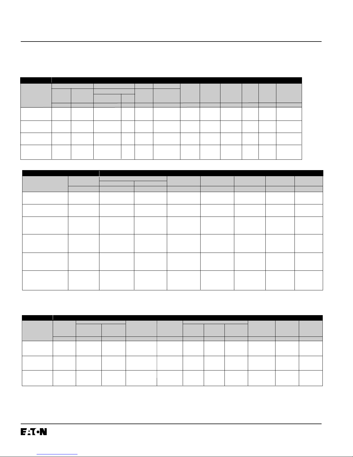
Table 1.3 (ANSI Standards) Type VCP-WC Extra Capability Vacuum Circuit Breaker 5-15 kV Rated Symmetrical
Current Basis
Close and Latch
Capability
Momentary
kA Peak
Identification Rated Values
Circuit Voltage
➁
Insulation Level Normal Current Short Circuit Transient Recovery Voltage Short Short Cable
Breaker Type Power Lightening Breaking U
c
t
3
t
d
Time Circuit Charging
Frequency Impulse Current (3 Second) Making Breaking
Withstand Current Current Current
kV rms kV rms kV Peak Amperes kA rms kA Peak µs µs kA rms kA Peak Amperes
240VCP-W16 24 60 125 630 16 41 88 13 16 40 31.5
1250
2000
240VCP-W20 24 60 125 630 20 41 88 13 20 50 31.5
1250
2000
240VCP-W25 24 60 125 630 25 41 88 13 25 63 31.5
1250
2000
I.B. 32-255-1G
Page 4
Effective 12/02
Table 1.5 (IEC-56 Standards➀) Type VCP-W Vacuum Circuit Breaker Through 17.5 kV Rated Symmetrical Current Basis
➀
Interrupting time is 3 cycles at 50/60 Hz. Rated operating sequence 0-3 minCO-3 min-CO.
Table 1.6 (IEC-56 Standards➀) Type VCP-W Vacuum Circuit Breaker Through 24 kV Rated Symmetrical Current Basis
➀
CESI certified for rated operating sequence: O-0.3 seconds-CO-15 seconds-CO
in accordance with IEC 56. Consult Cutler-Hammer for CESI certificates on file.
➁
Tested at 28.5 kV.
Identification Rated Values
Circuit Voltage Class Insulation Level Normal Current Short Circuit 3 Second Short Short Circuit Cable Charging
Breaker Type Power Frequency Impulse Withstand Breaking Current Time Current Making Current Breaking Amps
kV rms kV Peak kV Peak Amperes kA rms kA rms kA Peak Amperes
36VCPW-ND25 3.6 10 40 630, 1250 25 25 63 25
36VCPW-ND32 3.6 10 40 630, 1250 31.5 31.5 79 25
72VCPW-ND25 7.2 20 60 630, 1250 25 25 63 25
72VCPW-ND32 7.2 20 60 630, 1250 31.5 31.5 79 25
36VCP-W25 3.6 10 40 630, 1250, 2000 25 25 63 25
36VCP-W32 3.6 10 40 1250, 2000 31.5 31.5 79 25
36VCP-W40 3.6 10 40 1250, 2000 40 40 100 25
72VCP-W25 7.2 20 60 630, 1250, 2000 25 25 63 25
72VCP-W32 7.2 20 60 1250, 2000 31.5 31.5 79 25
72VCP-W40 7.2 20 60 1250, 2000 40 40 100 25
120VCP-W25 12.0 28 75 630, 1250, 2000 25 25 63 25
120VCP-W32 12.0 28 75 1250, 2000 31.5 31.5 79 25
120VCP-W40 12.0 28 75 1250, 2000 40 40 100 25
175VCP-W25 17.5 38 95 1250, 2000 25 25 63 31.5
175VCP-W32 17.5 38 95 1250, 2000 31.5 31.5 79 31.5
175VCP-W40 17.5 38 95 1250, 2000 40 40 100 31.5
Table 1.4 (ANSI Standards) Type VCP-WG Generator Vacuum Circuit Breaker Through 5-15 kV Rated Symmetrical
Current Basis
Circuit
Breaker Type
50VCP-WG50
50VCP-WG63
150VCP-WG50
150VCP-WG63
Voltage
Maximum Voltage
Voltage Range Factor
E K
kV rms
Insulation Level
Withstand Test Voltage
Power Frequency Impulse
(1 minute)
kV rms kV Peak
Current
Continuous Short Circuit
Current Current (at Rated
at 60 Hz Maximum kV)
I
Amperes kA rms
Interrupting
Time
Cycles
Permissible
Tripping
Time
Y
Seconds
Maximum
Voltage
Divided by K
E/K
kV rms
Peak
Voltage
E2
kV
Time-toPeak
t2
µs
4.76 1 19 60
4.76 1 19 60
15.0 1 36 95
15.0 1 36 95
1200
2000
3000
1200
2000
3000
1200
2000
3000
1200
2000
3000
50 3 2 4.76 27 8.8 137
63 3 2 4.76 28 9.0 173
50 3 2 15.0 27 3.5 137
63 3 2 15.0 28 3.5 173
Identification Rated Values

I.B. 32-255-1G
Page 5
Effective 12/02
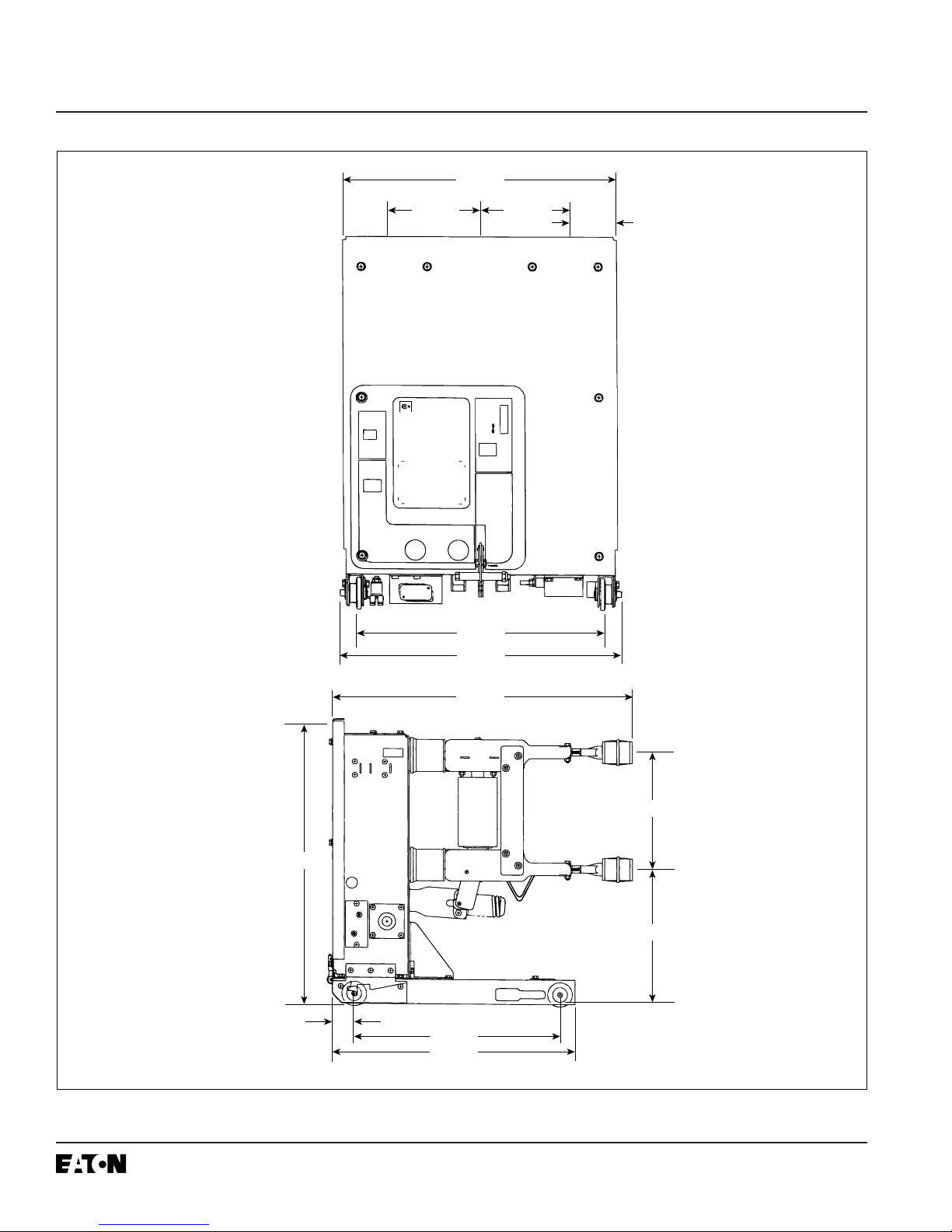
1-4 OUTLINES AND DIMENSIONS
Figure 1-1 Type VCP-W and Type VCPW-SE Circuit Breaker Outlines and Dimensions in inches
Breaker Identification ABCDE
240 VCP-W, 270 VCP-W & 270 VCP-WC 10.00 14.00 16.25 34.80 35.22
50/350, 50/350C, 150/1000, 150/1000C, 150/63, 10.00 12.00 13.63 29.94 31.22
All 3000A VCP-W, VCPW-SE, VCP-WG & VCP-WC
Except those immediately below
All Other VCP-W & VCPW-SE including 50/25C & 10.00 12.00 13.63 29.81 29.44
150/75C, 1200A
29.13
A
A
D
B
2.25
E
C
20.88
24.63
Cutler-Hammer
Vacuum
Breaker
Operation
Circuit Breaker
Counter
VCP-W
Main
Contact
Status
Push
To
Close
CLOSING
SPRING
Manual
Charge
Socket
Status
BREAKER
LATCH
To Latch:
Push Breaker In
Until Audible Latch
To Unlatch:
Lift & Pull Handle
To Withdrawn
Position
Push
To
Open
Do Not
Lift Handle
When Inserting
Breaker
27.80
29.56
I.B. 32-255-1G
Page 6
Effective 12/02
Figure 1-2 Type VCPW-ND Circuit Breaker Outlines and Dimensions in inches
21.38
Breaker
Operation
Counter
Main
Contact
Status
7.00
Cutler-Hammer
Vacuum
Circuit Breaker
VCPW-ND
Push
To
Close
Push
To
Open
CLOSING
SPRING
Manual
Charge
Socket
Status
BREAKER
LATCH
To Latch:
Push Breaker In
Until Audible Latch
To Unlatch:
Lift & Pull Handle
To Withdrawn
Position
19.44
21.96
Do Not
Lift Handle
When Inserting
Breaker
7.00
3.69
30.38
29.44
2.25
20.88
24.63
12.00
13.63

I.B. 32-255-1G
Page 7
Effective 12/02
SECTION 2: SAFE PRACTICES
2-1 RECOMMENDATIONS
Type VCP-W Vacuum Circuit Breaker Elements are
equipped with high speed, high energy operating mechanisms. They are designed with several built-in interlocks and safety features to provide safe and proper
operating sequences.
TO PROTECT THE PERSONNEL ASSOCIATED WITH
INSTALLATION, OPERATION, AND MAINTENANCE
OF THESE CIRCUIT BREAKER ELEMENTS, THE
FOLLOWING PRACTICES MUST BE FOLLOWED:
• Only qualified persons, as defined in the local electrical code, who are familiar with the installation and
maintenance of medium voltage circuits and equipment, should be permitted to work on these circuit
breaker elements.
• Read these instructions carefully before attempting
any installation, operation or maintenance of these
breakers.
• Always remove the breakers from the enclosure
before performing any maintenance. Failure to do so
could result in electrical shock leading to death,
severe personal injury or property damage.
• BE EXTREMELY CAREFUL while the circuit breaker
is on the extension rails. Use provided rail clamps to
firmly hold the circuit breaker on the extension rails
while performing such activities as charging, closing
and tripping. Carelessness could cause the circuit
breaker to fall from the rails resulting in personal injury
to those in the area.
• Do not work on a closed breaker or a breaker with
closing springs charged. The closing spring should be
discharged and the main contacts open before working on the breaker. Failure to do so could result in cutting or crushing injuries.
• Do not use a circuit breaker by itself as the sole
means of isolating a high voltage circuit. Remove the
breaker to the DISCONNECT position and follow good
lockout and tagging rules, as well as all applicable
codes, regulations and work rules.
• Do not leave the breaker in an intermediate position in
the cell. Always have the breaker either in the TEST
or CONNECTED position. Failure to do so could result
in a flash over and possible death, personal injury or
property damage.
• Always remove the maintenance tool from the breaker
after charging the closing springs.
• Breakers are equipped with safety interlocks. Do not
defeat them. This may result in death, bodily injury or
equipment damage.
!
WARNING

I.B. 32-255-G
Page 8
Effective 12/02
SECTION 3: RECEIVING, HANDLING AND
STORAGE
3-1 GENERAL
Type VCP-W Vacuum Circuit Breaker Elements are
subjected to complete factory production tests and
inspection before being packed. They are shipped in
packages designed to provide maximum protection to
the equipment during shipment and storage and at the
same time to provide convenient handling. Tools, such
as the maintenance tool, are shipped separately.
3-2 RECEIVING
If the circuit breaker element is not to be used immediately but is to be placed in storage; maximum protection
can be obtained by keeping it packed as shipped.
Upon receipt of the equipment, inspect the containers
for any signs of damage or rough handling. Open the
containers carefully to avoid any damage to the contents. Use a nail puller rather than a crow bar when
required. When opening the containers, be careful to
save any loose items or hardware that may be otherwise discarded with the packing material. Check the
contents of each package against the packing list.
Examine the circuit breaker element for any signs of
shipping damage such as broken, missing or loose
hardware, damaged or deformed insulation and other
components. File claims immediately with the carrier if
damage or loss is detected and notify the nearest
Cutler-Hammer Office.
3-3 HANDLING
DO NOT USE ANY LIFTING DEVICE AS A PLATFORM FOR PERFORMING MAINTENANCE, REPAIR
OR ADJUSTMENT OF THE BREAKER OR FOR
OPENING, CLOSING THE CONTACTS OR CHARGING THE SPRINGS. THE CIRCUIT BREAKER ELEMENT MAY SLIP OR FALL CAUSING SEVERE PERSONAL INJURY. ALWAYS PERFORM MAINTENANCE, REPAIR AND ADJUSTMENTS ON A SOLID
WORK SURFACE CAPABLE OF SUPPORTING THE
BREAKER ELEMENT.
When a breaker element is ready for installation, a lifting
yoke in conjunction with an overhead lifter or portable
floor lifter can be used to move a breaker element.
When a breaker element is to be lifted, position the lifting yoke over the breaker element and insert lifters into
the breaker element side openings with the lifting hole
toward the interrupters. Once the lifting yoke is securely
seated in the holes, the breaker element can be carefully lifted and moved.
3-4 STORAGE
If the circuit breaker element is to be placed in storage,
maximum protection can be obtained by keeping it
packed as shipped. Before placing it in storage, checks
should be made to make sure that the breaker element
is free from shipping damage and is in satisfactory operating condition.
The circuit breaker element is shipped with its contacts
open and closing springs discharged. The indicators on
the front panel should confirm this. Insert the maintenance tool in the manual charge socket opening (Figure
3-3). Charge the closing springs by pumping the handle
up and down approximately 38 times until a crisp metallic “click” is heard. This indicates that the closing springs
are charged and is shown by the closing spring
“charged” (yellow) indicator. Remove the maintenance
tool. Operate the push-to-close button. The breaker element will close as shown by the breaker contacts
“closed” (red) indicator. Operate the push-to-open button. The breaker element will trip as shown by the
breaker contacts “open” (green) indicator. After completing this initial check, leave the closing springs “discharged” and breaker contacts “open”.
Outdoor storage of the breaker element is NOT recommended. If unavoidable, the outdoor location must be
well drained and a temporary shelter from sun, rain,
snow, corrosive fumes, dirt, falling objects and excessive moisture must be provided. Containers should be
arranged to permit free circulation of air on all sides and
temporary heaters should be used to minimize condensation. Moisture can cause rusting of metal parts and
deterioration of high voltage insulation. A heat level of
approximately 400 watts for each 100 cubic feet of volume is recommended with the heaters distributed uniformly throughout the structure near the floor.
Indoor storage should be in a building with sufficient
heat and air circulation to prevent condensation. If the
building is not heated, the same general rule for heat as
for outdoor storage should be applied.
!
CAUTION
I.B. 32-255-1G
Page 9
Effective 12/02
3-5 TOOLS AND ACCESSORIES
Tools and accessories, both standard and optional are
available for use with the circuit breaker element (Figure
3-1).
Spin-Free Levering-In Crank: Used to crank breaker
between TEST and CONNECTED positions (Style
701B601G11).
Standard Levering-In Crank: (Style 701B601G12).
Maintenance Tool: Used to charge closing springs
manually (Style 8064A02G11).
Extension Rails: Permits breaker to be withdrawn from
its compartment (Style 7813C41G03 for VCP-W and
VCPW-SE) and (Style 7813C41G04 for VCPW-ND).
Rail Clamps: Used to secure breaker to extension rails
(Style 6511C83G11 for VCP-W and VCP-SE) and (Style
6511C83G02 for VCPW-ND).
Lifting Yoke: Used to lift breaker (Style 691C607G11
for VCP-W and VCPW-SE) and (Style 691C607G02 for
VCPW-ND).
Drawout Ramp: Used to insert or withdraw breaker
from lower compartment without portable lifter (Style
1C14163G02 for VCP-W and VCPW-SE) and (Style
1C14163G01 for VCPW-ND).
Portable Lifter: Used to lift breaker to or from extended rails (Style 1C14504H01).
Docking Transport Dolly: Used to insert or withdraw
breaker from lower compartment without portable lifter
or move breaker from one location to another (Style
6510C71G11 for VCP-W and VCPW-SE) and (Style
6510C71G02 for VCPW-ND).
Electrical Levering-In Device: Used to electrically
move breaker between TEST and CONNECTED positions (Style 1A30257G01).
Test Jumper: Used to operate breaker electrically
while breaker is on extension rails or transport dolly
(Style 6526C23G11 for VCP-W and VCPW-SE) and
(Style 1C15331G01 for VCPW-ND).
Test Cabinet: Used to provide power to operate breaker outside its compartment (Styles 8346A28G21 – G23
for VCP-W and VCPW-SE depending upon voltage
requirements) and (Styles 8346A28G41 – 43 for VCPWND depending upon voltage requirements).
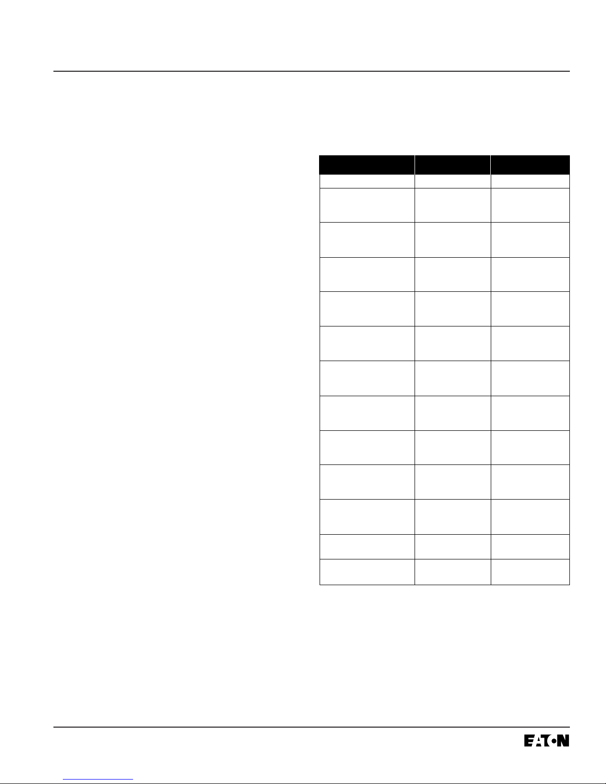
Table 3.1 VCP-W ANSI Rated Breaker Weights
➀
Rating Amperes Lbs. (kg)
50VCPW-ND250 1200 345 (157)
50VCP-W250 1200 350 (159)
50VCPW-SE250 2000 410 (186)
3000 525 (238)
50VCP-W350 1200 460 (209)
50VCPW-SE350 2000 490 (222)
3000 525 (238)
75VCP-W500 1200 375 (170)
75VCPW-SE500 2000 410 (186)
3000 525 (238)
150VCP-W500 1200 350 (159)
150VCPW-SE500 2000 410 (186)
3000 525 (238)
150VCP-W750 1200 350 (159)
150VCPW-SE750 2000 410 (186)
3000 525 (238)
150VCP-W1000 1200 460 (209)
150VCPW-SE1000 2000 490 (222)
3000 525 (238)
150VCP-W1500
(63)
1200 525 (238)
150VCPW-SE1500
(63)
2000 530 (241)
3000 550 (250)
270VCP-W750
(16)
600 460 (209)
1200 480 (218)
2000 500 (227)
270VCP-W1000
(22)
600 460 (209)
1200 480 (218)
2000 500 (227)
270VCP-W1250
(25)
600 460 (209)
1200 480 (218)
2000 500 (227)
270VCP-W1600
(32)
1200 545 (245)
2000 560 (252)
270VCP-W2000
(40)
1200 545 (245)
2000 560 (252)
3-6 TYPE VCP-W VACUUM CIRCUIT BREAKER
ELEMENT WEIGHTS (TABLES 3.1 AND 3.2)
➀
Does not include shipping carton.

I.B. 32-255-G
Page 10
Effective 12/02
Normal
Rating Current Lbs. (kg)
Amperes
36VCPW-ND25 630 350 (159)
1250 350 (159)
36VCPW-ND32 630 350 (159)
1250 350 (159)
72VCPW-ND25 630 350 (159)
1250 350 (159)
72VCPW-ND32 630 350 (159)
1250 350 (159)
36VCP-W25 630 350 (159)
1250 350 (159)
2000 410 (186)
36VCP-W32 1250 350 (159)
2000 410 (186)
36VCP-W40 1250 375 (170)
2000 410 (186)
72VCP-W25 630 350 (159)
1250 350 (159)
2000 410 (186)
72VCP-W32 1250 350 (159)
2000 410 (186)
72VCP-W40 1250 375 (170)
2000 410 (186)
120VCP-W25 630 350 (159)
1250 350 (159)
2000 410 (186)
120VCP-W32 1250 350 (159)
2000 410 (186)
120VCP-W40 1250 375 (170)
2000 410 (186)
175VCP-W25 630 350 (159)
1250 350 (159)
2000 410 (186)
175VCP-W32 1250 375 (170)
2000 410 (186)
175VCP-W40 1250 375 (170)
2000 410 (186)
240VCP-W16 630 462 (210)
1250 484 (220)
2000 506 (230)
240VCP-W20 630 462 (210)
1250 484 (220)
2000 506 (230)
240VCP-W25 630 462 (210)
1250 484 (220)
2000 506 (230)
➀
Does not include shipping carton.
Table 3.2 VCP-W IEC Rated Breaker Weights
➀
I.B. 32-255-1G
Page 11
Effective 12/02
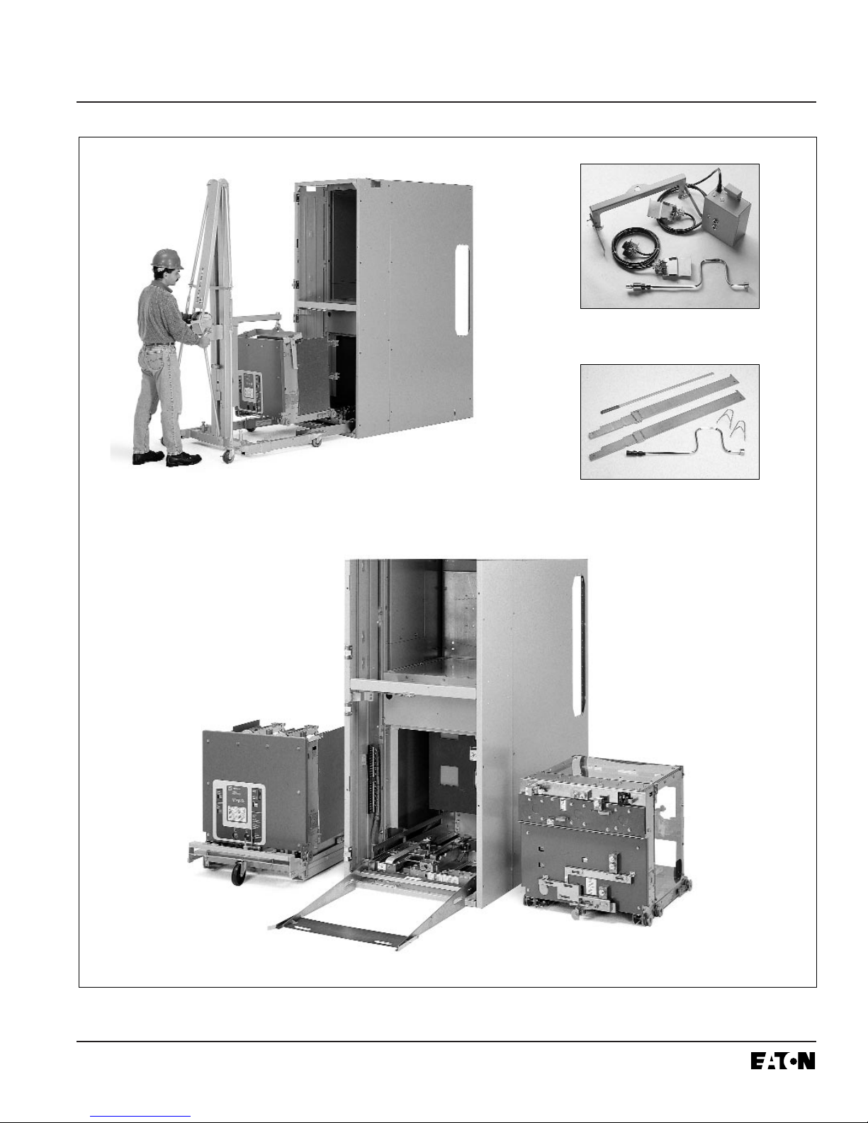
Figure 3-1 Typical VCP-W Tools and Accessories
Optional portable lifter
Optional accessories
Standard accessories
Optional dockable dolly
Optional drawout ramp
Optional ground and test
devices and dummy elements
I.B. 32-255-G
Page 12
Effective 12/02
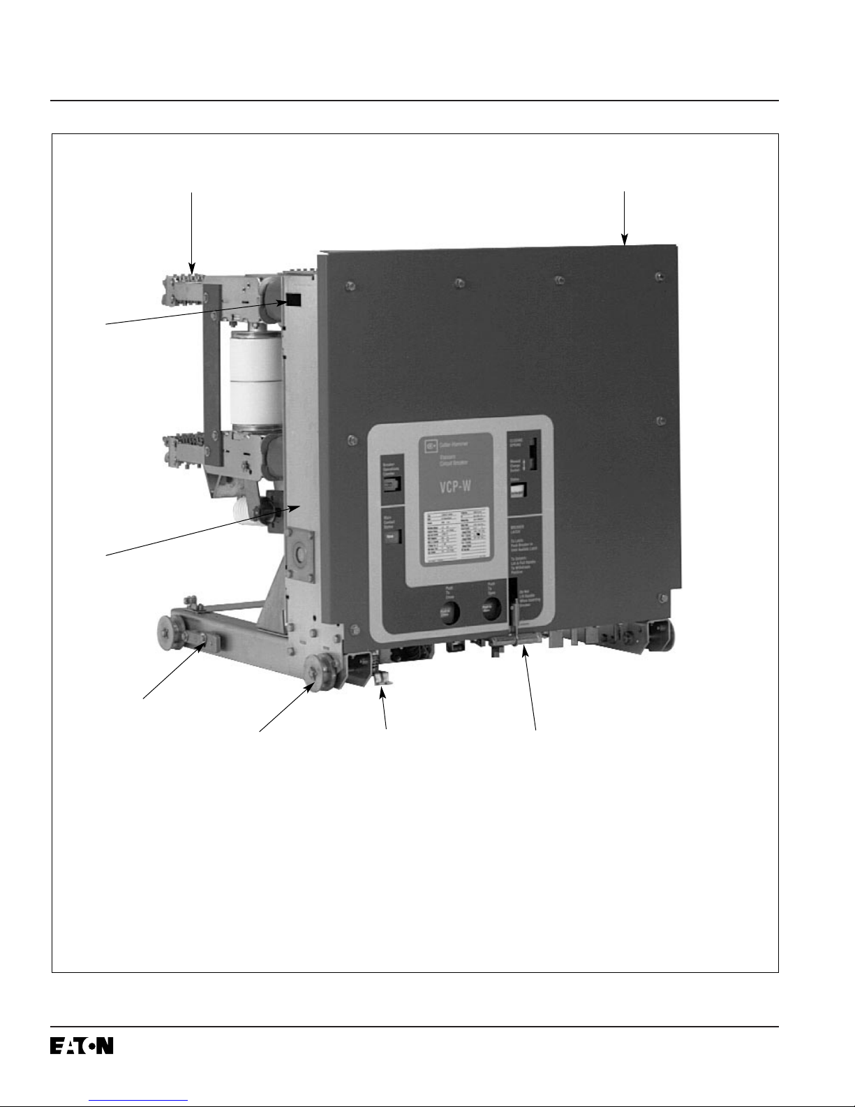
Figure 3-2 Typical Front View VCP-W Vacuum Circuit Breaker Element
➄ Mechanism Enclosure
➅ Lifting Yoke Opening
➆ Primary Disconnect
➇ Ground Contact
➀ Front Panel
➁ Lift/Pull Handle
➂ Wheel
➃ Extension Rail Interlock
➀
➁
➃
➇
➆
➅
➄
➂
I.B. 32-255-1G
Page 13
Effective 12/02
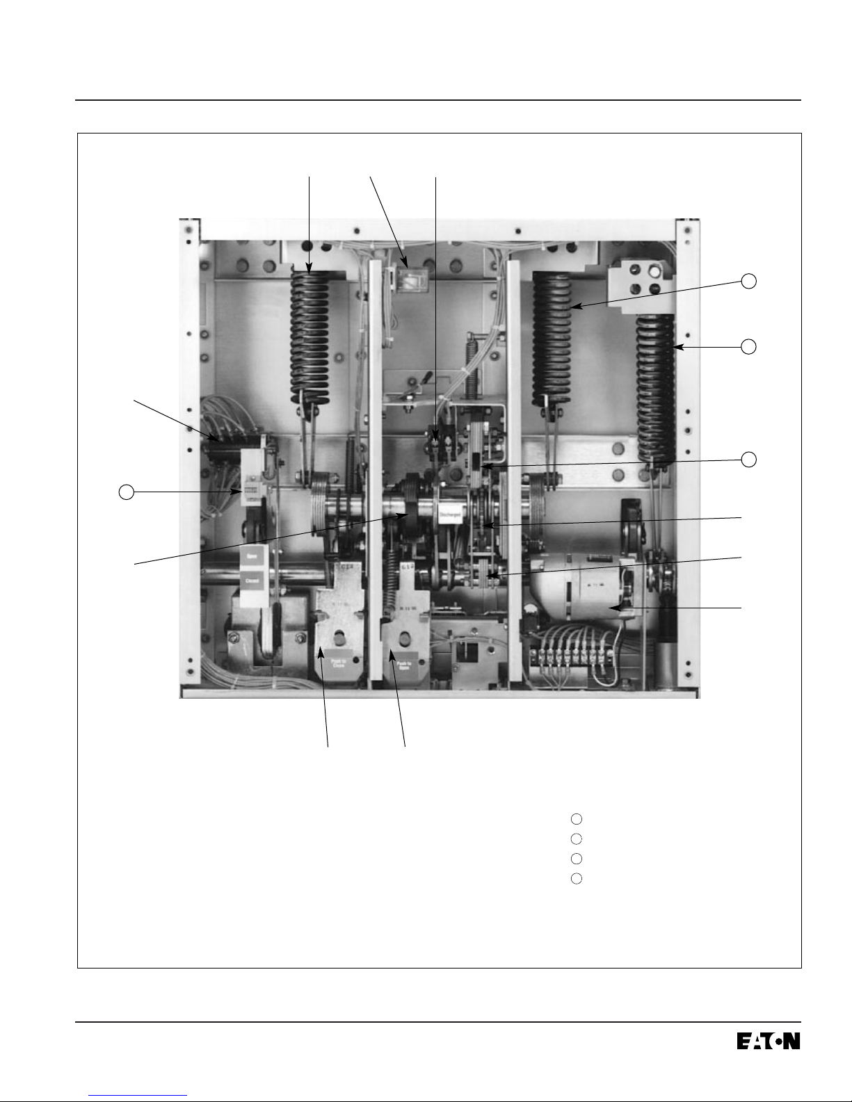
Figure 3-3 Typical VCP-W Vacuum Circuit Breaker Element with Front Cover Removed
➅ Spring Release (Close Coil)
Assembly
➆ Shunt Trip Assembly
➇ Charging Motor
➈ Charging Pawl
➉ Ratchet Wheel
ƒ R. H. Closing Spring
≈ Opening Spring
∆ Manual Charge Socket
∆ Operation Counter
➀➁➃
➇
➈
13
➆
➅
➄
➂
➀ L.H. Closing Spring
➁ Anti-Pump Relay
➂ Auxiliary Switch
➃ Motor Cutoff Switch
➄ Closing Cam
14
11
12
➉
13
11
12
14
 Loading...