

Eaton 455U-D User Manual
ELPRO Technologies Pty Ltd, 9/12 Billabong Street, Stafford Q 4053, Australia.
Tel: +61 7 3352 8600 Fax: +61 7 3352 8677
Email: Elpro-Sales@eaton.com Web: www.eaton.com/wireless
User Manual
455U-D
Radio Modem

Contents
Man_455U-D Rev 3.07 Page 3
Thank you for your selection of the 455U-D radio modem. We trust it will give
you many years of valuable service.
ATTENTION!
Incorrect termination of supply wires may
cause internal damage and will void warranty.
To ensure your 455U-D enjoys a long life,
double check ALL your connections with
the user’s manual
before turning the power on.
Important Regulatory Information
FCC
Part 15 – This device has been tested and found to comply with the limits for a Class
B digital device, pursuant to Part15 of the FCC rules (Code of Federal
Regulations 47CFR Part 15). Operation is subject to the condition that this
device does not cause harmful interference.
Part 90 – This device has been type accepted for operation by the FCC in accordance
with Part90 of the FCC rules (47CFR Part 90). See the label on the unit for
the specific FCC ID and any other certification designations.
Note This device should only be connected to PCs that are covered by either a
FCC DoC or are FCC certified.
Industry Canada
RSS-119 - This device has been type accepted for operation by Industry Canada in
accordance with RSS-119 of the Industry Canada rules. See the label on the
unit for the specific Industry Canada certification number and any other
certification designations.
Notice
Any changes or modifications not expressly approved by ELPRO
Technologies P/L could void the user’s authority to operate this equipment.
To operate this equipment legally the user must obtain a radio operating
license from the government agency. This is done so the government can
coordinate radio users in order to minimize interference.

455U-D Radio Modem User Manual
Page 4 © Jan 2016
How to Use This Manual
To receive the maximum benefit from your 455U-D product, please read the
Introduction, Installation and Configuration chapters of this manual
thoroughly before putting the 455U-D to work.
Chapter Four Specifications details the features of the product and lists the
standards to which the product is approved.
Chapter Five Troubleshooting will help if your system has problems and
Chapter Seven specifies the Warranty and Service conditions.
The foldout sheet 455U-D Installation Guide is an installation drawing
appropriate for most applications.
WARNING
1. To avoid the risk of electrocution, the antenna, antenna cable, and all
terminals of the 455U-D module should be electrically protected. To
provide maximum surge and lightning protection, the module should be
connected to a suitable earth and the antenna, antenna cable, and the
module should be installed as recommended in the Installation Guide.
2. To avoid accidents during maintenance or adjustment of remotely
controlled equipment, all equipment should be first disconnected from the
455U-D module during these adjustments. Equipment should carry clear
markings to indicate remote or automatic operation. eg. "This equipment
is remotely controlled and may start without warning. Isolate at the
switchboard before attempting adjustments."
3. The 455U-D module is not suitable for use in explosive environments
without additional protection.
4. All antenna installation and servicing should be done by qualified
personal only. When installing or working near the antenna it is
important to ensure that the transmitter is not operating, ensure the
transmitter is disabled.
5. The antenna can have very high RF radiating fields and must be installed
so that under normal operating conditions that a person cannot approach
within 2.3 metres (7.5 feet) of the antenna. See chapter 2 for antenna
installation guidelines.

Contents
Man_455U-D Rev 3.07 Page 5
CONTENTS
WARNING ............................................................................................................................... 4
CHAPTER ONE INTRODUCTION ..................................................................... 8
1.1 GENERAL ................................................................................................................. 8
1.1.1 Basic Operation ......................................................................................................... 9
1.1.2 Operating Modes ....................................................................................................... 9
1.1.3 Repeater Functionality ............................................................................................. 10
1.1.4 Hot Redundant Standby ........................................................................................... 10
1.2 UNACKNOWLEDGED MODE.................................................................................... 10
1.3 ACKNOWLEDGED MODE ........................................................................................ 11
1.4 SECURITY ENCRYPTION ......................................................................................... 14
1.5 SERIAL AND RADIO DATA ...................................................................................... 14
1.5.1 PLC-Mode ............................................................................................................... 15
1.5.2 Character Type ......................................................................................................... 15
1.5.3 Serial Data Rate ....................................................................................................... 16
1.5.4 Radio Data Rate ....................................................................................................... 16
1.5.5 Radio Message ......................................................................................................... 16
1.6 ADDRESSING .......................................................................................................... 17
1.6.1 Multiple Device Connectivity (MDC) ..................................................................... 18
1.7 OPTIMUM PATH ROUTING ...................................................................................... 18
1.8 DUTY CYCLE LIMITING .......................................................................................... 19
1.9 WHAT OPERATING MODE TO USE ? ....................................................................... 19
1.9.1 Unacknowledged or Acknowledged mode? ............................................................ 19
1.9.2 Error Check ? ........................................................................................................... 20
CHAPTER TWO INSTALLATION .................................................................. 21
2.1 GENERAL ............................................................................................................... 21
2.2 ANTENNA INSTALLATION ....................................................................................... 21
2.2.1 3dB/6dB Collinear antenna. .................................................................................... 23
2.2.2 Yagi antennas. ......................................................................................................... 24
2.3 POWER SUPPLY ...................................................................................................... 24
2.4 SERIAL CONNECTIONS ........................................................................................... 26
2.4.1 RS232 Serial Port ................................................................................................ 26
2.4.2 RS232 Configuration Port ................................................................................... 27
2.4.3 RS485 Serial Port ................................................................................................ 27
2.5 DISCRETE I/O POINT .............................................................................................. 28
2.5.1 Using the Discrete I/O as an Output .................................................................... 28
2.5.2 Using the Discrete I/O point as an Input .............................................................. 28
CHAPTER THREE CONFIGURATION ........................................................................ 29

455U-D Radio Modem User Manual
Page 6 © Jan 2016
3.1 BEFORE CONFIGURING ........................................................................................... 29
3.1.1 Addressing ............................................................................................................... 29
3.1.2 Command Mode ...................................................................................................... 30
3.2 DEFAULT CONFIGURATION .................................................................................... 30
3.3 CONFIGURATION PROGRAM ................................................................................... 30
3.3.1 Reading and Configuring a module ......................................................................... 31
3.3.2 Saving and Opening a configuration file ............................................................. 32
3.3.3 Modifying an existing configuration ................................................................... 32
3.3.4 Serial Communications terminal ......................................................................... 33
3.3.5 Reset and Advanced mode .................................................................................. 33
3.5 UNACKNOWLEDGED MODE.................................................................................... 35
3.5.1 RS-485 Port ............................................................................................................. 35
3.5.2 RS-232 Port ............................................................................................................. 36
3.5.3 Unacknowledged mode Repeaters ....................................................................... 37
3.5.4 Broadcast Network .............................................................................................. 38
3.5.5 Addressed Network ............................................................................................. 39
3.5.6 Multiple Transmissions ....................................................................................... 40
3.6 RADIO AND SERIAL CONFIGURATION ..................................................................... 40
3.6.1 Radio Data Rate ....................................................................................................... 40
3.6.2 Serial Port Settings .................................................................................................. 40
3.6.3 Other Settings .......................................................................................................... 41
3.7 ACKNOWLEDGED MODE ........................................................................................ 42
3.7.1 Auto Dial (Auto-Connect Master) ....................................................................... 42
3.7.2 Auto Answer (Auto-Connect Slave) .................................................................... 44
3.7.3 Single-Connect Acknowledged mode ................................................................. 44
3.8 DUAL REDUNDANCY ............................................................................................. 45
3.8.1 Single Host Device .............................................................................................. 46
3.8.2 Redundant Host Pair ............................................................................................ 46
3.8.3 Dual Redundanct Control Connection ................................................................. 47
3.8.4 Dual Redundant Indications ................................................................................ 48
3.8.5 Firmware versions prior to 3.03 .......................................................................... 50
3.9 LOW POWER MODE ............................................................................................... 51
3.10 OPTIMUM PATH ROUTING ...................................................................................... 52
3.10.1 Path Configuration ............................................................................................... 52
3.10.2 Configuring for Modbus Protocol (RTU or ASCII) ............................................ 53
3.10.3 Modbus RTU Protocol ........................................................................................ 54
3.10.4 Modbus ASCII protocol ...................................................................................... 54
3.10.5 DF1 protocol ........................................................................................................ 54
3.10.6 DNP3 ................................................................................................................... 54
3.11 ADVANCED SETTINGS - S REGISTERS ..................................................................... 54
3.12 HAYES AT COMMANDS ......................................................................................... 54
3.13 AT CONFIGURATION EXAMPLES ............................................................................ 55

Contents
Man_455U-D Rev 3.07 Page 7
3.13.1 Data Logger Network with Central Computer .................................................... 55
3.13.2 Unacknowledged mode with broadcast messages and repeaters. ........................ 56
3.14 SWITCH CONFIGURATION ....................................................................................... 57
CHAPTER FOUR TROUBLESHOOTING .................................................................... 58
4.1 POWER-UP AND NORMAL OPERATION ................................................................... 58
4.2 LED INDICATION DIAGNOSTICS CHART ................................................................. 59
4.3 OPERATING PROBLEMS .......................................................................................... 60
4.4 TEST FUNCTIONS ................................................................................................... 61
4.4.1 Bit Error Ratio Test (BER) ...................................................................................... 61
4.4.2 Other Radio Testing - AT&Tx ................................................................................ 62
4.4.3 On-line diagnostics .................................................................................................. 63
4.5 RADIO PATH TESTING ............................................................................................ 65
4.6 CHANGING THE RADIO PARAMETERS ..................................................................... 66
4.7 DIAGNOSTIC MESSAGES ........................................................................................ 67
CHAPTER FIVE SPECIFICATIONS ............................................................................. 68
CHAPTER SIX WARRANTY & SERVICE ................................................................... 71
APPENDIX A HAYES COMMANDS ............................................................................. 72
APPENDIX B RESPONSE CODES ................................................................................ 81
APPENDIX C S-REGISTERS .......................................................................................... 82

455U-D Radio Modem User Manual
Page 8 © Jan 2016
Chapter One INTRODUCTION
1.1 General
The 455U-D radio modem provides reliable radio modem operation with advanced
communication control and diagnostics functions. Radio modems transmit serial data over a
long distance via radio. The serial data is not changed - the output data is the same as the
input data. Although the 455U-D is intended to be simple in its application, it also provides
many sophisticated features. This manual should be read carefully to ensure that the modules
are configured and installed to give reliable performance.
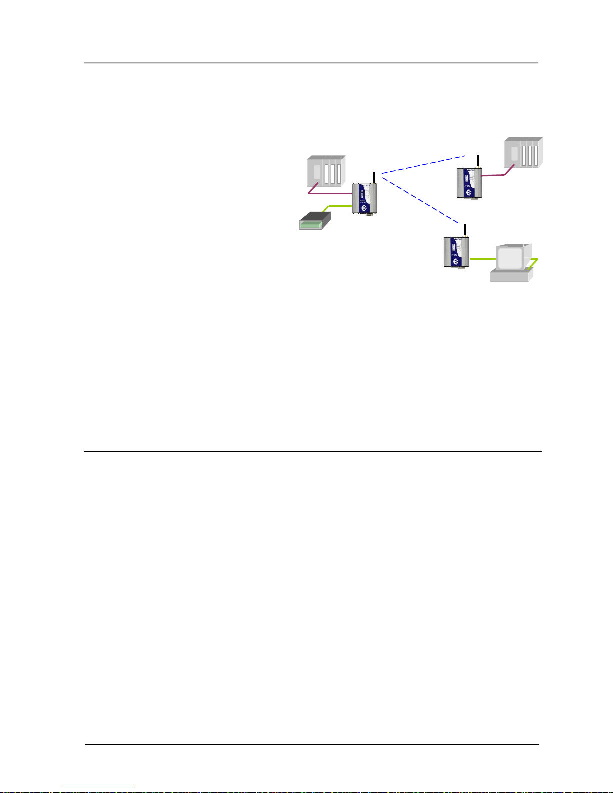
Each 455U-D module will connect to a host device by RS232 or RS485 serial connection.
Examples of host devices are PLC’s, data loggers, intelligent transducers and computers. The
455U-D unit can receive data from the host device and transmit this data by radio to another
(or several) 455U-D module. The other module will recreate the serial data and output it as
either a RS232 or RS485 serial signal. The 455U-D unit provides two-way communications each module can accept serial data and also output serial data.
The 455U-D module has two data ports (one RS232 and one RS485) and can connect to two
host devices independently. The 455U-D also has another RS232 port (via a RJ45 connector)
which can be used only for configuration or access to diagnostics information - the RS232 data
port can also be used for configuration and diagnostics.
RS232 is an electrical standard format for a full duplex point-to-point serial connection.
RS485 is an electrical standard format for a half-duplex multidrop serial connection. Up
to 32 devices can communicate on a common RS485 serial bus.
Each 455U-D can simultaneously
connect to signals from both RS232 and
RS485. In addition, RS232 data from
one host device can be transmitted to a
remote 455U-D unit and output as
RS485 data to another host device.
The unit includes a fixed frequency
radio transceiver. A range of models
support operation in the following
bands: 58 to 72MHz; 148 to 174MHz;
220 to 235 MHz; and seven 20MHz radio bands in the range of 360 to 512MHz. The user can
configure the frequency within the radio band (refer to Diagnostics section).
The 455U-D is available with a high power radio (0.5 – 5W) suitable for licensed narrowwidth channels (12.5, 20 or 25KHz). The models operating in the 360 to 512MHz range are
also available with a lower power radio (10 – 500mW) suitable for license-free narrow-width
channels, in countries where these are available.
The operating parameters of the 455U-D are configured from a PC using a Microsoft
Windows configuration package provided free with the module, or from a PC terminal using
Hayes commands.
RS232
RS232
RS485
RS485
MULTIPLE DEVICE CONNECTIVITY

Chapter One Introduction
Man_455U-D Rev 3.07 Page 9
Ordering Information
455U - Type – Radio Type – RF Power – Channel – Band – Frequency
Type D Data modem, full functionality
B Data modem, Bell 202 or V23 messaging
A External modem, 600 ohm audio input
C Data modem compatible with ELPRO 405U *only 400MHz models
Radio Type L 10 – 500mW H 0.5 – 5W
Power Actual power requested - for example, 100mW or 2W
Channel N 12.5 KHz W 20/25 KHz
Band 60 58 – 72MHz 150 148 – 174 MHz
220 220 – 235 Mhz (note: 220 model is wide band only)
390 380 – 400 MHz 410 400 – 420 MHz
430 420 – 440 MHz 440 430 – 450 MHz
460 450 – 470 MHz 480 470 – 490 MHz
500 490 – 512 MHz
Frequency Actual frequency requested in MHz - for example, 471.0725
For different transmit and receive frequencies, enter Rxxxxx/Txxxxxx,
for example, R460.5000/T472.3000
1.1.1 Basic Operation
The operation of the 455U-D radio modem is relatively simple. As data is received at the
serial port, the data is transmitted on the radio channel. Up to 1020 bytes of data can be
transmitted in one transmission. The radio transmission commences when the first data byte is
received, and ends when there are no more data bytes in the input buffer, or when the number
of bytes transmitted equals the maximum message length (user configurable - default 1020
bytes). If more than 1020 bytes is input, the 455U-D unit will transmit the first 1020 bytes,
then the next 1020 bytes, and so on until all of the data has been transmitted.
Because the radio data rate could be less than the input serial data rate, an input memory
buffer of up to 8Kbytes is provided. The RS232 connection provides CTS control to prevent
the buffer overflowing. There are no data flow control signals for RS485.
1.1.2 Operating Modes
A radio channel cannot provide as secure a data channel as a wired connection. The 455U-D
uses a radio band with a low level of natural or industrial noise, however there is a chance of
interference from other users on the radio channel. We recommend that the flow of data over
the radio channel is controlled by using error detection and “handshaking” - that is, returning
an acknowledgment transmission if a data packet is received on the radio channel without
error. This function can be performed by either the host devices or the 455U-D modules.
The modules may be configured by the user to operate in one of two modes. In
Unacknowledged mode, it is assumed that the host devices control the flow of data - the
455U-D does not provide handshaking. In Acknowledged mode, the 455U-D units provide
handshaking to control the flow of data.
The RS485 port always operates in Unacknowledged mode.
455U-D Radio Modem User Manual
Page 10 © Jan 2016
1.1.3 Repeater Functionality
A 455U-D unit can act as a repeater for other units. A repeater receives a radio message from
one unit and re-transmits it on to another unit.
Up to seven repeater addresses can be configured in a radio link.
If transmitting to the wildcard 0 address in Unacknowledged mode (that is, a broadcast
transmission), then the repeater unit can be configured to also output the data to its own host
device.
1.1.4 Hot Redundant Standby
Two 455U-D units can be installed together in a Dual Redundant relationship - an active unit
with a hot redundant standby. One unit is configured as a “primary” unit and the other the
“secondary”. The secondary unit acts as a standby for the primary.
Under normal operation, the primary unit is active and the standby is inactive. If the internal
diagnostics in the primary detects a fault or an operating problem, the primary stops normal
operation and the secondary becomes active. The inactive unit is powered and operational,
however communications out of the unit via the radio transmitter and RS485 port is disabled.
Both units have the same configuration apart from primary/secondary selection.
1.2 Unacknowledged Mode
The default configuration of the 455U-D modem is unacknowledged mode - the modules are
set in this mode at the factory.
In unacknowledged mode,
units do not provide
handshaking functions to
control the flow of data.
Messages are not
acknowledged, and are sent
on a “Best attempt” basis. It
is up to the host equipment
to determine if data is lost or
corrupted.
To improve reliability in this mode, units may be configured to send each message multiple
times (configured in S-Register S29). The receiving unit will detect repeat messages and only
send the data out the serial port once.
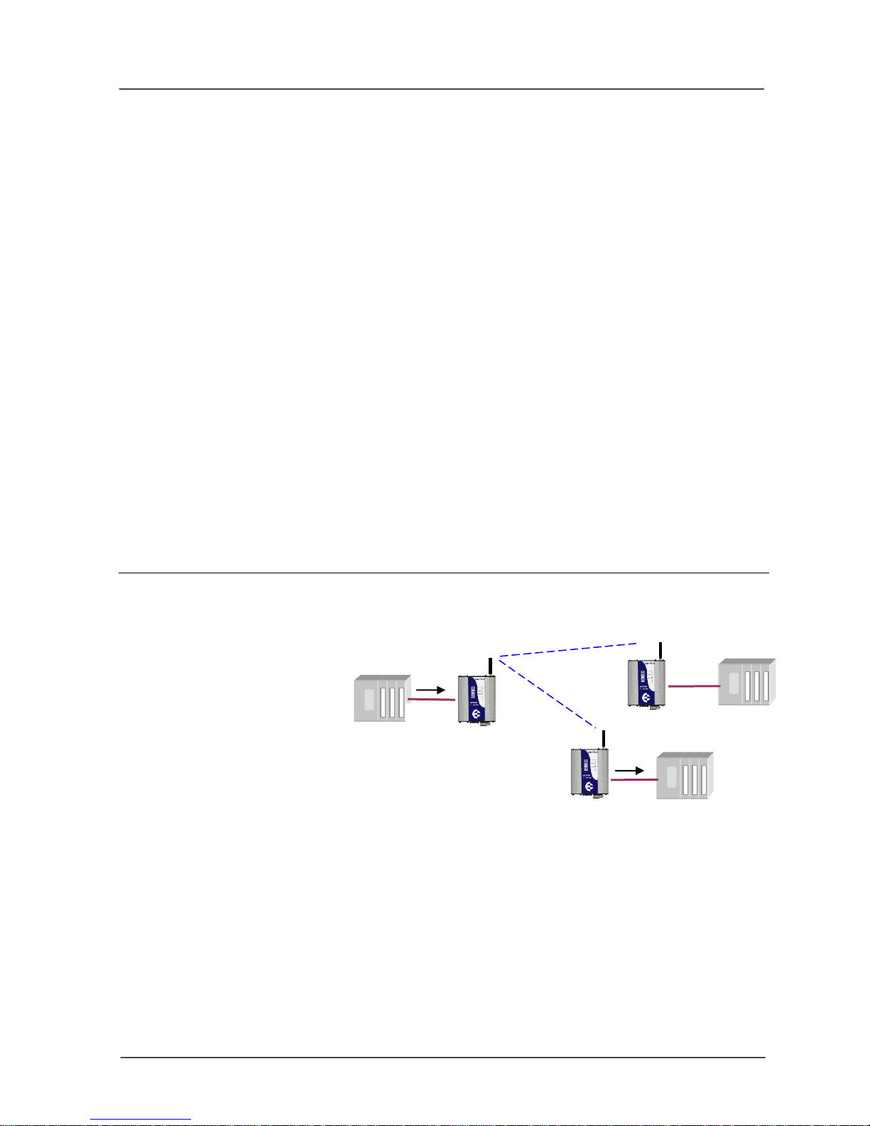
Each modem is configured with a separate unit address. In Unacknowledged mode, messages
may be sent
to a particular modem by using the remote unit’s address, or
UNACKNOWLEDGED MODE
ADDRESSED TO A PARTICULAR
UNIT
DATA
DATA
NO
Chapter One Introduction
Man_455U-D Rev 3.07 Page 11
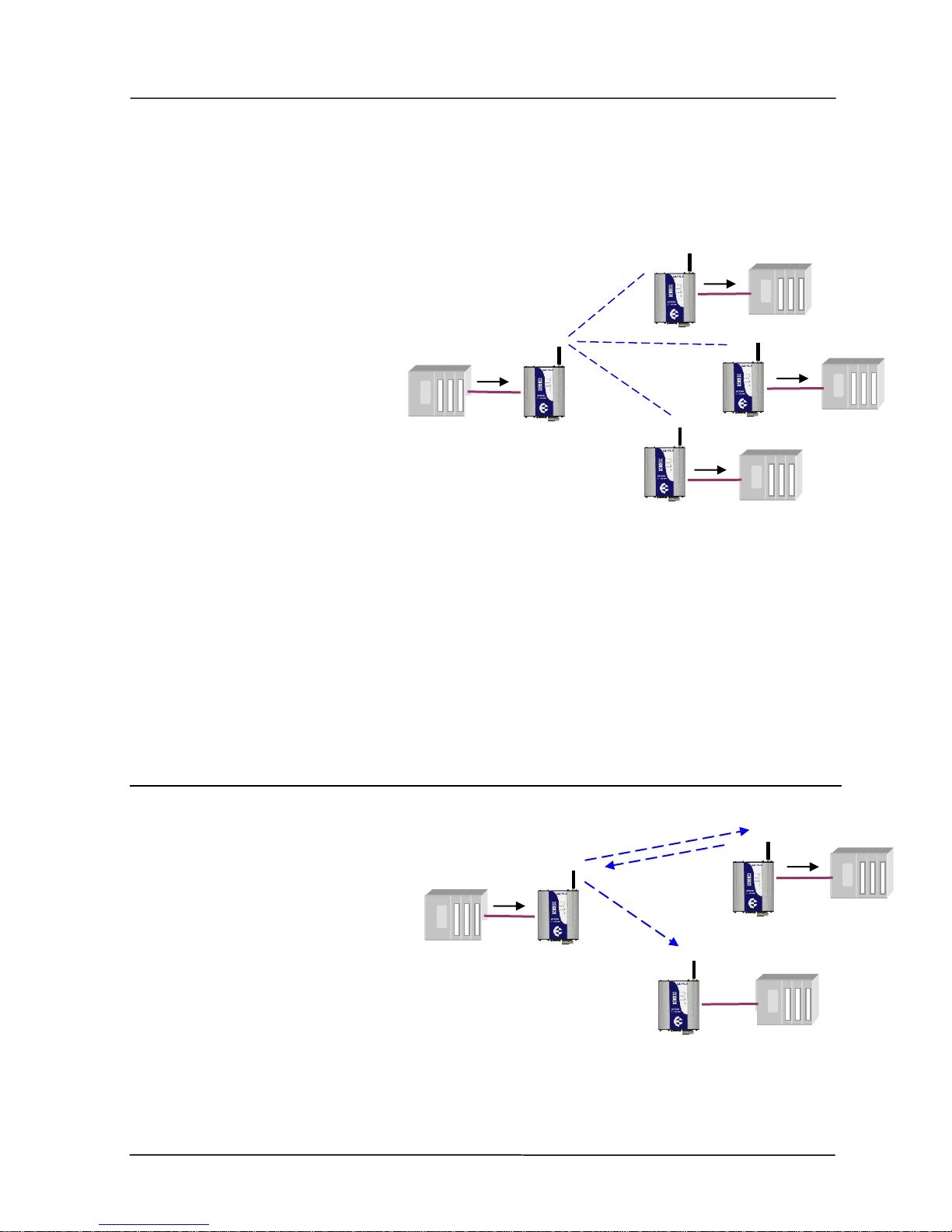
UNACKNOWLEDGED MODE
ADDRESSED TO ALL UNITS USING
WILDCARD ADDRESS 0
DATA
DATA
DATA
DATA
to all modems in the system, as a broadcast message by using the wildcard address 0. The
wildcard address is used to send a message to a group of modems.
Data received at the serial port is transmitted out of the radio port, addressed to the configured
destination 455U-D module, or to all modules by using address 0. Data received from the
radio with the correct addressing is transmitted out of one of the serial ports (RS232 or
RS485).
Prior to transmitting, units will listen to the radio channel to
ensure that it is clear - units will hold off from
transmitting until the radio channel is clear.
At the RS232 port, the CTS pin
can be configured to go high while
there is space in the input data
buffer - otherwise it is always high.
Host devices should provide a
suitable protocol to ensure that
error checking, handshaking and implementation of an
appropriate re-transmission scheme is provided. This mode of operation is particularly suited
to devices designed to operate over a multidrop network, such as PLC systems designed for
operation over a RS-485 network.
If error checking is not configured at the receiving unit, data will start to be output
immediately after the first byte of data has been received. If error checking is configured, data
will be output approx 1mSec after the end of the message. For example, a message with 20
bytes of data transmitted at 19200 bits/sec will begin to be output approx 23 msec after the
data is input, if there is no error checking, or 31 msec after the data is input if error checking is
configured - this assumes the minimum lead-in time of 20 msec is configured.
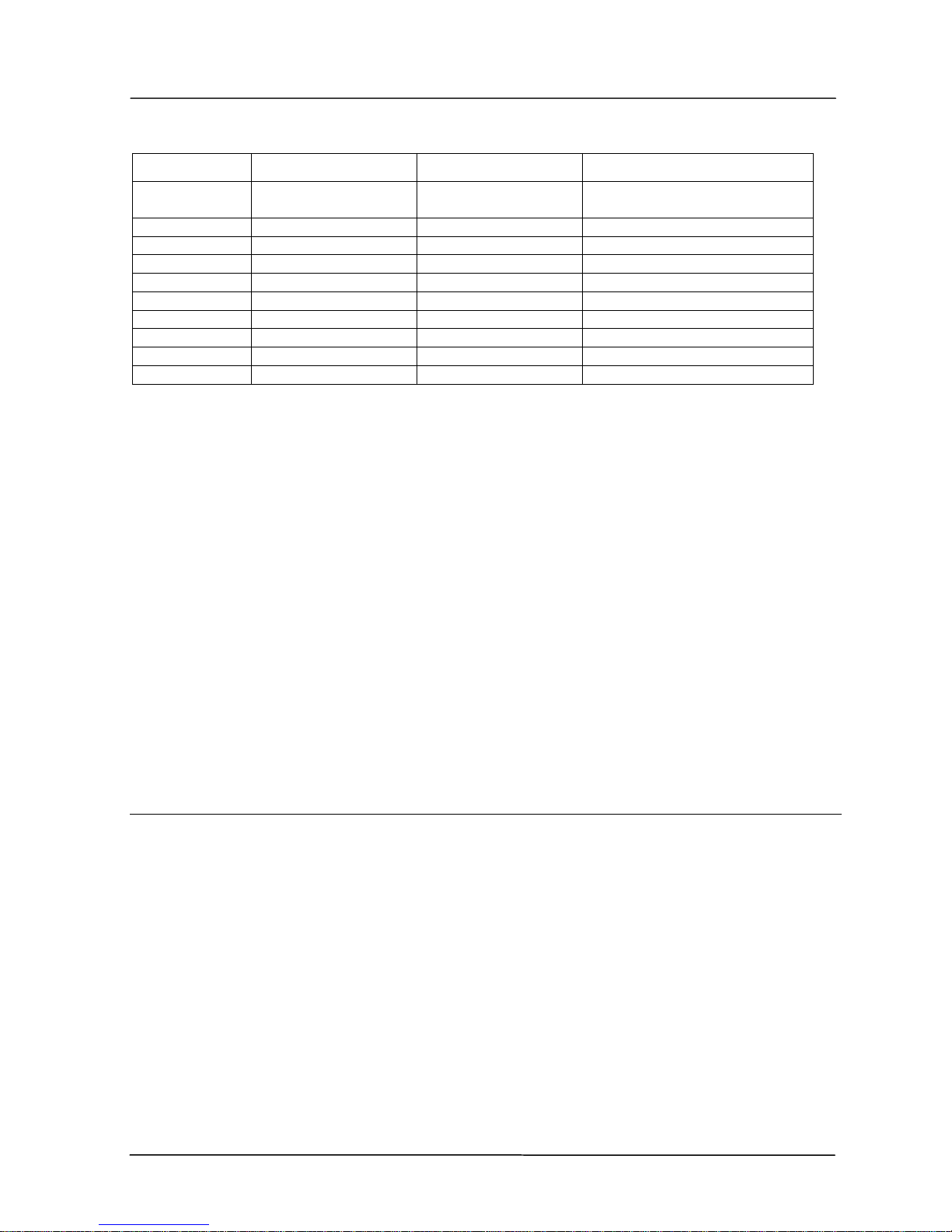
1.3 Acknowledged Mode
In Acknowledged mode, data is
transferred between the RS-232
ports of two modules (that is, a
point to point link). One of the
modules is configured as a
“master” (or initiator) unit and the
other as a “slave” (or responder)
unit. There can be many slave
units in the system; however the
master unit will only link to one
slave at any one time.
Note that Acknowledged mode only applies to the RS-232 port. The RS-485 port always
operates in Unacknowledged mode.
ACKNOWLEDGED MODE
DATA
DATA
NO
DATA MESSAGE
ACK

455U-D Radio Modem User Manual
Page 12 © Jan 2016
To establish a link, the master unit transmits a special “connect” message. This initial message
does not include any data. If the addressed slave unit receives the connect message, and is not
already connected to another 455U-D unit, it will return an acknowledgment message. Both
units will activate their DCD LED, and also activate their DCD output signal (if configured).
If the master unit does not receive the acknowledgment, the DCD output will reset. When the
connection is made (DCD set), the 455U-D units can transmit data to each other.
A master can be configured to connect to a pre-configured slave address in two ways:
on power up - the master will only connect to one fixed slave address and if the
connection link fails, the master will continuously try to make a new connection, or
it can be “commanded” by its host device using AT commands - the host device can
control the master 455U-D to “dial” a slave address, connect, transfer data, and then
disconnect (or “hang up”), and connect to a different slave address.
Once the communications channel has been established, the 455U-D unit will accept input
data and send radio messages with data. When a 455U-D unit receives a radio message, it will
check the system address and destination address, and also the error-check (optional). If these
are correct, it will return a ACK (acknowledgment) message to the source unit. If the system
address or destination address is not correct, or if the error-check is not correct, then no return
message is sent.
There can also be up to five intermediate repeaters in the link. Each 455U-D unit is
configured with a unit address - only the unit with an address matching the destination address
of the radio message will process the message and output the serial data.
Establishing a Communications Link
Master Unit
Slave Unit
Listen to ensure channel is clear
If clear, transmit “connect” message
Radio TX LED flashes
----------------->
Receives message
Radio RX LED flashes
Check system and destination
address
If OK, set DCD LED and output
Radio RX LED flashes
<-----------------
If message OK, transmit back an
ACK message.
Radio TX LED flashes
Acknowledgment received okay
communication link established
Set DCD LED and output
If the source unit does not receive an ACK message, it will re-transmit the same message. It
will attempt to transmit the message the configured number of times (S-Register S30). If the
unit still does not receive an ACK message after the configured number of attempts, it will

Chapter One Introduction
Man_455U-D Rev 3.07 Page 13
reset the LINK LED, and reset the DCD output on the DB9 RS232 port and reset the DIO
output (if configured).
During normal operation, if there has been no radio activity for a period (called the “link
check” period), the master unit will transmit a “check” message to check the radio path. The
link check period is user-configurable (S-Register S6). If the slave doesn’t receive any
messages within the configured link check timeout (Configuration Setting \T), it will drop the
radio link, and turn off the LINK LED, and reset the DIO and DCD signals (if configured).
Successful Communications
Source Module
Destination Module
Serial data is received
Serial LED flashes
Listen to ensure channel is clear
If clear, transmit message
Radio TX LED flashes
----------------->
Receive message
Radio RX LED flashes
Check system and destination
address
If OK, check error-check
Radio RX LED flashes
<-----------------
If message okay, transmit back
an ACK message.
Radio TX LED flashes
Acknowledgment received okay -
communication complete
Serial data is output
Serial LED flashes
Unsuccessful Communications
Source Module
Destination Module
Listen to ensure channel is clear
If clear, transmit message
TX LED flashes
----------------->
Receives message
RX LED flashes
Check system and destination
address
If incorrect, transmit no message
and no serial output.
No ACK received
Retry multiple times (Configure With
S-Register S30)
----------------->
If no ACK message received after
all attempts
“NO CARRIER” message sent to
host
DCD signal and DCD LED reset

455U-D Radio Modem User Manual
Page 14 © Jan 2016
1.4 Security Encryption
Some applications require that the system be made secure from eavesdropping and hacking.
To provide for these applications, the modem supports AES-128 data encryption.
The modem may be configured to transmit messages with or without encryption, accept
messages without encryption, or to require that received messages are encrypted.
Messages sent with encryption have an additional 16 bytes of data added to the start of the
radio message (the initialization vector).
1.5 Serial and Radio Data
The 455U-D module provides a full-duplex RS232 serial port and half-duplex RS485 serial
port. The radio communications is half-duplex. Many applications use full duplex RS232
communications but do not require full duplex - the protocol used operates at half-duplex and
will operate with the 455U-D without problems. If an application really requires full duplex
communications, then the 455U-D should not be used.
Data input at the serial port is placed into the input buffer. This buffer will store up to
8Kbytes of data, and CTS/RTS control can be configured on the RS232 port to prevent
overflow.
When the 455U-D unit detects data in the input buffer, it initiates a radio message. The radio
message will end when the number of transmitted bytes reaches the maximum message length
(configurable by the user), or if the input buffer becomes empty.
If the configured serial data rate is the same or more than the radio data rate, then data is
transmitted as soon as it enters the input buffer - data “streams” from the input buffer to the
radio port. If the serial rate is less than the radio rate, then the transmission will be delayed for
a period to allow sufficient data to build up in the input buffer to avoid the radio emptying the
input buffer before a complete serial message has been input. This delay is configurable
separately for the RS232 and RS485 serial ports. Alternatively a Transmitter Hold up time can
be configured (S-Register S27) to keep the transmitter keyed up between characters.
The radio transmission will stop when the input buffer is empty or when the radio has
transmitted the maximum number of bytes (user configurable - maximum 1020 bytes). If
there is still data in the input buffer, the 455U-D will start another radio transmission.
An error-check can be added to each radio message - this is a user-configurable selection. If
error checking is configured, then a 16 bit CRC error-check is added to the end of the
transmitted data packet. The receiving module will receive the full data packet and check the
CRC before outputting the data.
The maximum size of the data packet is configurable by the user (maximum is 1020 bytes). If
less data than the maximum size is input to the 455U-D, then the 455U-D will transmit the
actual data input. If more data is input than the maximum size, then the 455U-D will transmit
multiple packets until all of the data is transmitted.

Chapter One Introduction
Man_455U-D Rev 3.07 Page 15
Because of radio start-up delays, the effective radio data rate will be lower than the transmitted
data rate. If you are sending large blocks of data, and the serial rate is equal or more than the
radio rate, we recommend that you use CTS/RTS flow control to prevent the input buffer from
overflowing.
1.5.1 PLC-Mode
The 455U-D will operate most efficiently when the serial data rate is higher or the same as the
radio data rate. If the serial data rate is less than the radio rate, there is a risk that the radio
will empty the input buffer too quickly, resulting in a single input message being broken into
more than one output messages. Many host protocols such as those used by PLC’s, will not
accept a message being broken into sections with delays between the sub-sections.
To avoid this occurring, the 455U-D will automatically delay the radio transmission starting if
the serial rate is less than the radio rate. This is called “PLC Mode”. The radio will not start
transmitting until a certain number of bytes have been input into the input buffer. The 455UD calculates the number of starting bytes depending on the values of the configured serial and
radio rates. The number of bytes to start transmitting is stored in register S18 (S20 for RS485))
- when a configuration is entered whereby the serial rate is less than the radio rate, the 455U
configuration software will automatically enter an appropriate value in S18. The user can
change this value. If the serial rate is the same as the radio rate, or more, than there is no
delay.
There is an automatic protection - if a certain time has elapsed and the number of starting
bytes has not been input, then the radio will start transmitting. This is an override protection.
The 455U-D will automatically calculate the override time based on the configured serial rate
and S18 (the number of bytes required to start). The override time is stored in register S19
(S21 for RS485) - this value can also be changed by the user.
In applications where the extra delay introduced by buffering data at the sending modem is
unacceptable, an alternative is to configure a “Transmitter Hold up” time (S-Register S27).
This keeps the transmission keyed up between data characters.
1.5.2 Character Type
The 455U-D may be configured by the user to
recognize the following types of characters - 7 or 8
data bits, even or odd or no parity, 1 or 2 stop bits.
Most applications will require the character type to be
the same at each 455U-D modem in the system.
Nevertheless, the character type may be configured to
be different at different 455U-D modems. Data is
transmitted by radio as an eight-bit byte without stop
or start bits. If the input data is 7 data bits, then the
byte transmitted by radio comprises the 7 bits plus a zero bit. Input characters with 8 bits are
transmitted as just the 8 data bits, with no parity. Because the data is transmitted without
parity, the user may configure CRC error checking to be added to each transmitted data packet.
Data is output at the destination module based on the character type configured at that module
- that is, the start/stop bits and parity is added to the radio data.
Data
Parity
Stop
7
Even
1
2
Odd
1 2 None
2 8 Even
1
Odd
1
None
1
2

455U-D Radio Modem User Manual
Page 16 © Jan 2016
1.5.3 Serial Data Rate
The communications baud rates supported on both the RS232 serial port and the RS485 serial
port are 600, 1200, 2400, 4800, 9600, 14400, 19200, 28800, 31250, 38400, 57600, 76800,
93750, 115200 and 187500 baud - the user selects one of these rates during the configuration of
the modem.
The RS232 and RS485 ports may be configured with separate data rates.
1.5.4 Radio Data Rate
The data is transmitted by radio as direct modulated synchronous data at 1200, 2400, 4800
9600, or 19200 bits/second - (19200 baud only operates with 25KHz channel widths). The
user must configure the radio data rate at each 455U-D module. The configured radio data
rates must be the same for each module in a system.
The 455U-D uses four-level frequency modulation for the highest data rates - 9600 b/s for
12.5 KHz channels and 19200 b/s for 25 KHz channels. The other rates use two level
frequency modulation. Two level modulation results in less data errors, resulting in more
reliable operation. It is recommended that radio rates of 4800 (12.5 KHz) or 9600 (25 KHz)
be used unless the application requires the higher data rates.
1.5.5 Radio Message
The radio message includes the following: A 40 msec leading sequence of alternating 1’s and 0’s provides the receiving unit with
time to capture and lock onto the incoming signal (the lead-in time can be configured to
be longer for systems using talk-through repeaters).
A system address is superimposed on each message to provide discrimination between
different 455U-D systems on the same radio channel. Each 455U-D unit in the same
system must be configured with the same system address - refer Configuration section.
Although other 455U-D modules may hear the radio transmissions, because they have a
different system address, the radio transmission is ignored and no serial data is output.
Addressing for the sending unit, any repeater units, and the final destination unit indicates
where the message is to be sent and how to get there.
An error-check (16 bit CRC) and security encryption (AES128) may be configured by the
user.
Up to 1020 bytes of data may be transmitted in a message - the maximum message size is
configurable between 1 and 1020 bytes. The data consists of a sequence of 8 bit bytes. Start,
stop and parity bits are not transmitted, but they are re-generated at the receiving unit (if
configured).
Chapter One Introduction
Man_455U-D Rev 3.07 Page 17
The time taken to transmit a message is :-
Section
Item
Number
Time (At 9600 Baud)
PEAMBLE
Lead-in
40 msec Default
(Configurable)
40 msec
HEADER
System Address
2 Bytes
2.08 msec
Header Control
2 Bytes
2.08 msec
Source Address
1 Byte
1.04 msec
Destination Address
1 Byte
1.04 msec
Intermediate Address
1 Byte per address
1.04 msec for each address
Header Error Check
1 Byte
1.04 msec
ENCRYPTION
Initialisation Vector
16 Bytes (if enabled)
16.64 msec (If configured)
DATA
Message Data
Data Bytes
1.04 msec x no of data bytes
CHECK
CRC Error Check
2 bytes (if enabled)
2.08 msec (If CRC configured).
The time for each byte is 1.04msec @9600 bits/sec, 2.08 msec at 4800 bits/sec, and 4.16 msec
at 2400 bits/sec.. If error checking is not configured at the receiving unit, data will start to be
output immediately after the first data byte has been received. If error checking is configured,
data will be output approx 1msec after the end of the message. For example, a message with
20 bytes of data transmitted at 9600 bits/sec with no repeaters, will start to be output approx
71msec after the data is input, if error checking is configured, and will start to be output
approx 47 msec after the data is input if no error checking is configured.
A “transmit delay” time and a “receive delay” time may also be configured. These parameters
may be used to fine tune and give priority to different 455U-D units in a system.
After each message is transmitted, a 455U-D unit will not transmit another message during
the transmit delay time. This could be used to allow a reply message to be received before
the next message is sent.
After a message is received, a message will not be transmitted during the receive delay time.
This could be used to delay a reply message until other messages have been sent.
1.6 Addressing
A 455U-D network comprises modules with the same "system" address. Only modules with
the same system address will communicate with each other. This feature allows more than one
system to operate in the same area on the same radio channel.
A 455U-D must also be configured with a “unit” address - this gives the module a unique
identification. The unit address is used to identify the two data ports on each 455U-D. The
RS232 port is accessed by addressing the configured unit address. The RS485 port is accessed
by addressing the configured unit address +128. So, to access the RS232 port on unit 7, use
address 7. To access the RS485 port on this unit, use address 135 (128+7).
Addresses 0 and 128 are reserved as “wildcard” addresses. Sending a message to address 0
results in all modules accepting the message. Address 0 refers to every RS232 port in the
system. Address 128 is the wildcard address for every RS485 port in the system.
455U-D Radio Modem User Manual
Page 18 © Jan 2016
1.6.1 Multiple Device Connectivity (MDC)
Because each serial port is individually addressed, the 455U-D is able to connect to two serial
devices and manage two independent wireless links. This is called Multiple Device
Connectivity, or MDC functionality.
Some of the features if MDC are:
Each serial port is configured
individually however with the same
system address.
The device connected to the RS485
port can link to the RS485 port or the
RS232 port on another 455U-D - the
same applies to the RS232 device.
However if a wild-card address is used
(0 or 128), then all remote serial ports must be the same - that is, all R485 or all RS232.
The RS485 port always operates in Unacknowledged mode. The RS232 port can be in
Unacknowledged or Acknowledged mode. The DCD status indication will relate to the
RS232 port.
Each wireless link can include repeater addresses.
Because both communications channels use the same radio channel, activity on one port
may impact communications on the other port, by introducing delays in message
transmission.
1.7 Optimum Path Routing
Optimum Path Routing (OPR) is an advanced feature providing fast and efficient radio
networking. OPR is a protocol-specific feature using the link layer of a variety of host
protocols, allowing routing of messages for up to 64 different host addresses.
Supported host protocols are:
DF1 (half duplex master and slave),
Modbus (Master and Slave) - RTU and ASCII formats,
Profibus (Peer-to-Peer) and
DNP3 (peer-to-peer).
Under OPR, a “path” is configured for each host protocol address, comprising the 455U
destination address and any 455U repeater addresses in the path. When the 455U unit receives
a data message from its host, the 455U will interrogate the message for the host destination
address and use the pre-configured OPR path to send the radio message.
For more information, refer to section 3 of this Manual.
RS232
RS232
RS485
RS485
MULTIPLE DEVICE CONNECTIVITY

Chapter One Introduction
Man_455U-D Rev 3.07 Page 19
1.8 Duty Cycle Limiting
Some licenses require that the modem limits its communications so that it is transmitting for
no more than a maximum proportion of the available time. This applies to European 500mW
380-520MHz unlicensed bands, where the modem must limit its duty cycle to 10%.
Duty cycle limit is set to 100% except for modems which are configured for the European
limited duty cycle bands.
To change the duty cycle limit, use the AT#D command. (AT#D100 for 100%).
Duty cycle limiting must be calculated over a time no greater than one hour. You might prefer
to calculate the duty cycle limit over a shorter time. The AT#T command sets the time in
minutes to use to calculate the duty cycle.
1.9 What Operating Mode to Use ?
1.9.1 Unacknowledged or Acknowledged mode?
Unacknowledged mode provides simpler operation as the units do not acknowledge
transmissions received. However confirmed operation in unacknowledged mode will only occur
if the host devices check the messages and return acknowledgments. Generally, if a device is
able to operate on a RS485 multi-drop serial link, it is suitable for unacknowledged mode.
The RS-485 port only operates in Unacknowledged mode. It is possible for the RS-485 port to be
operating at the same time as the RS-232 port is sending data to another location, using either
Acknowledged or Unacknowledged mode (MDC).
RS-232 links can also be made in Unacknowledged mode - the 455U units can effectively
provide a “multi-drop” network for RS232 devices, provided the devices use a communications
protocol that includes addressing and message acknowledgments.
Normally Unacknowledged mode would be used with PLC’s and similar devices.
Acknowledged mode is suitable for point-to-point RS-232 links where the host devices do not
provide addressing or message acknowledgment. Multi-point networks are possible in
Acknowledged mode, however a “master” host device must control connecting and
disconnecting to remote units using AT commands.
It is possible to configure different units in the same system with different operating modes,
however this requires care. A 455U-D unit configured in one mode can act as a repeater for
messages sent between two 455U-D units configured in the other mode, and it is always possible
to send Unacknowledged mode messages to the RS-485 port on a module regardless of the
configuration of the RS-232 port.

455U-D Radio Modem User Manual
Page 20 © Jan 2016
1.9.2 Error Check ?
Error-checking may be configured in both Unacknowledged and Acknowledged mode. When
the error-check is configured, a 16-bit CRC (Cyclic Redundancy Check) attached to the end of
each message. This check is used to detect any corruption of the data when it is received at
another 455U-D unit.
Error checking is individually selected for the RS232 port and the RS485 port.
When a unit receives a radio message with error-check, it will not output data until it has
received the whole message and ensured that the error-check is correct. If the unit does not have
error-check configured, then it will output data as it is received, streaming from the radio out the
serial port. Hence operation of the units is faster if error-check is not configured.
Usually units in the same system will have the same error-check configuration; however it is
possible for users to configure the units differently. Each message sent indicates within the
message header whether it uses error-checking or not, so a single modem can receive messages
with and without error checking without requiring changes to the configuration.
Error-check is strongly recommended for Acknowledged mode operation. If error-check is not
configured, then a 455U-D unit will transmit an acknowledgment message (ACK) whenever it
receives a radio message, without checking for errors. If error-check is configured, the unit will
only transmit an ACK message if the error-check is correct.
When using OPR with Modbus RTU or DNP3 protocols, error check should be disabled as these
incorporate their own error check within the data frame.
When using OPR with Modbus ASCII protocol, error check should be enabled as this protocol
only incorporates a weak LRC error check.
When using OPR with DF1 protocol, Error check must be enabled if the DF1 protocol is
configured for Block Character Check (BCC). Error check must be disabled if the DF1 protocol
is configured for Cyclic Redundancy Check (CRC). Best performance is found when DF1 is
configured to use CRC, and Error check is disabled on the 455U-D.

Chapter Two Installation
Man_455U-D Rev 3.07 Page 21
Chapter Two INSTALLATION
2.1 General
The 455U-D module is housed in a rugged aluminum case suitable for DIN-rail mounting.
Terminals will accept wires up to 2.5 sqmm (12 gauge) in size.
Normal 110-240V AC supply should not be connected to any terminal of the 455U-D
module. Refer to Section 2.3 Power Supply.
To operate this equipment legally the user must operate on a designated license-free radio
channel and within the operating parameters of the license-free channel, or obtain a radio
operating license from the responsible government agency. This is done so the government can
coordinate radio users in order to minimize interference.
Before installing a new system, it is preferable to bench test the complete system.
Configuration problems are easier to recognize when the system units are adjacent. Following
installation, the most common problem is poor communications caused by incorrectly installed
antennas, or radio interference on the same channel, or the radio path being inadequate. If the
radio path is a problem (ie path too long, or obstructions in the way) then higher performance
antennas or a higher mounting point for the antenna may rectify the problem. Alternately, use
an intermediate 455U-D Module as a repeater.
The foldout sheet 455U-D Installation Guide provides an installation drawing appropriate to
most applications. Further information is detailed below.
Each 455U-D module should be effectively earthed via the "GND" terminal on the 455U-D
module - this is to ensure that the surge protection circuits inside the 455U-D module are
effective.
2.2 Antenna Installation
The 455U-D module will operate reliably over large distances. The distance which may be
reliably achieved will vary with each application - depending on the type and location of
antennas, the degree of radio interference, and obstructions (such as hills or trees) to the radio
path. The expected range depends on the configured radio data rate and radio bandwidth.
Data Rate
Radio Bandwidth
Expected Range
4800 baud
12.5kHz
60 km (40 miles)
9600 baud
12.5kHz
30 km (20 miles)
9600 baud
25kHz
60 km (40 miles)
19,200 baud
25kHz
30 km (20 miles)
Where it is not possible to achieve reliable communications between two 455U-D modules,
then a third 455U-D module may be used to receive the message and re-transmit it. This
module is referred to as a repeater.

455U-D Radio Modem User Manual
Page 22 © Jan 2016
An antenna must be connected to each 455U-D module using the female SMA connector at
the top of the module.
To achieve the maximum transmission distance, the antennas should be raised above
intermediate obstructions such that the radio path is true “line of sight”. Because of the
curvature of the earth, the antennas will need to be elevated at least 5 metres (15 feet) above
ground for paths of 5 km (3 miles). For short distances, the modules will operate reliably with
some obstruction of the radio path. Obstructions which are close to either antenna will have
more of a blocking effect than obstructions in the middle of the radio path. For example, a
group of trees around the antenna is a large obstruction, and the antenna should be raised
above the trees. However if there is at least 100 meters (300 feet) of clear path before a group
of trees, the trees will have less effect on the radio path. To help in planning radio systems,
ELPRO provides a free utility for estimating path performance.
The modules provide test diagnostics to test the radio path and display radio signal strength.
An antenna should be connected to the module via 50 ohm coaxial cable (eg RG58, Cellfoil or
RG213) terminated with a male SMA connector. The higher the antenna is mounted, the
greater the transmission range will be, however as the length of coaxial cable increases so do
cable losses. For use on unlicensed frequency channels, there are several types of antennas
suitable for use. It is important antennas are chosen carefully to avoid contravening the
maximum allowed power limit on the on the radio channel - if in doubt refer to a authorized
ELPRO distributor in your country or email ELPRO on support@elprotech.com.
The gains and losses of some typical antennas and cable types are
Antenna
450MHz Gain (dB)
150/220MHz Gain (dB)
60MHz Gain (dB)
Dipole with integral cable
0 0 0
3dBd Collinear
5
5 (only 150MHz)
N/A
6dBd Collinear
8
N/A
N/A
6 element Yagi
9
N/A
N/A
9 element Yagi
12
N/A
N/A
16 element Yagi
15
N/A
N/A
Cable type
Loss @ 450MHz
(dB per 10 m)
Loss @ 150/220MHz
(dB per 10 m)
RG58
-4.5
-2.4 (-2.8)
-1.3
RG213
-1.65
-0.9 (-1.1)
-0.5
Cellfoil
-2.25
-1.4 (-1.7)
-0.9
The net gain of the antenna/cable configuration is determined by adding the antenna gain and
the cable loss. For example, at 450MHz a 6dBd Collinear with 20 metres of RG58 has a net
loss of 1 dB (8dB – ((20/10) x 4.5) dB) = 8dB – 9dB = -1dB
Another important consideration when installing the antenna system is RF exposure. The
Chapter Two Installation
Man_455U-D Rev 3.07 Page 23
antenna can radiate a large amount of RF energy. It is important to ensure that a person cannot
approach the antennas within the recommended minimum safe distances in the table below.
Antenna Type
Minimum safe distance
(450MHz)
Minimum safe distance
(60/150/220MHz)
Dipole
0.4 metres
0.2 metres
3dBd Collinear
0.7 metres
0.4 metres
6dBd Collinear
0.9 metres
N/A
6 element Yagi
1.2 metres
N/A
9 element Yagi
1.5 metres
N/A
16 element Yagi
2.3 metres
N/A
Connections between the antenna and coaxial cable should be carefully taped to prevent
ingress of moisture. Moisture ingress in the coaxial cable is a common cause for problems
with radio systems, as it greatly increases the radio losses. We recommend that the connection
be taped with a layer of PVC insulating tape, then a layer of vulcanizing tape such as “3M 23
tape”, with a final layer of PVC insulating tape.
Where antennas are mounted on elevated masts, the masts should be effectively earthed to
avoid lightning surges. Although the 455U-D module is fitted with surge protection, additional
surge suppression devices are recommended if lightning surge problems are experienced. If
the antenna is not already shielded from lightning strike by an adjacent earthed structure, a
lightning rod may be installed above the antenna to provide shielding.
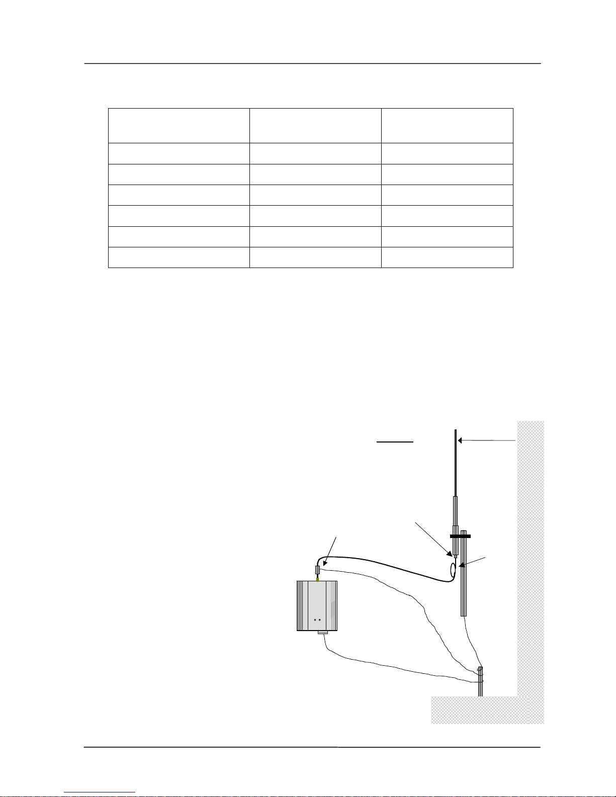
2.2.1 3dB/6dB Collinear antenna.
A collinear antenna transmits the same
amount of radio power in all directions as such they are easy to install and use.
For marginal radio paths, the following
lengths are the recommended maximum
for the coaxial cable to the antenna.
RG58 -10 meters, RG213 - 20 meters.
Note that this applies to marginal paths
only - if the radio path has a strong radio
signal, then longer lengths of cable (and
hence more cable loss) can be tolerated.
If more than 20 meters of cable is
required for a marginal path installation,
then a low loss cable such as 10D-FB, or
a higher gain antenna should be used.
Collinear antennas should be mounted
vertically, at least 1 meter away from a
wall or mast.
Wavelengths
450 MHz 66 cm
COLINEAR
ANTENNA
MAST
MODEM
SURGE ARRESTOR
(OPTIONAL)
COAXIAL CABLE
WEATHERPROOF
CONNECTORS WITH “3M
23” TAPE
PROVIDE GOOD GROUND
CONNECTION TO MAST, MODULE AND
SURGE ARRESTOR
GND
1 Wavelength minimum
IF GROUND CONDITIONS ARE POOR,
INSTALL MORE THAN ONE STAKE
STRESS RELIEF LOOP
220 MHz 163 cm
150 MHz 200 cm
455U-D Radio Modem User Manual
Page 24 © Jan 2016
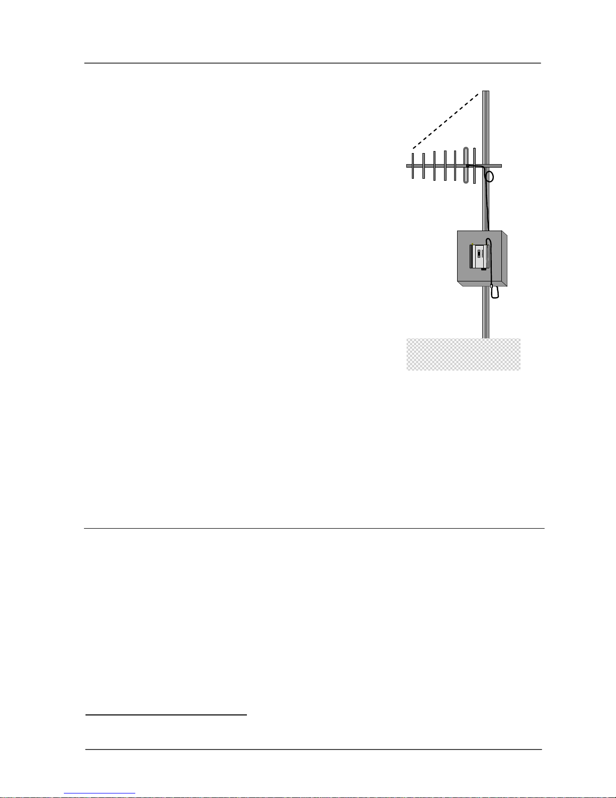
2.2.2 Yagi antennas.
A Yagi antenna provides high gain in the forward direction,
but lower gain in other directions. This may be used to
compensate for coaxial cable loss for installations with
marginal radio path.
The Yagi gain also acts on the receiver, so adding Yagi
antennas at both ends of a link provides a double
improvement.
Yagi antennas are directional. That is, they have positive gain
to the front of the antenna, but negative gain in other
directions. Hence Yagi antennas should be installed with the
central beam horizontal and must be pointed exactly in the
direction of transmission to benefit from the gain of the
antenna. The Yagi antennas may be installed with the
elements in a vertical plane (vertically polarized) or in a
horizontal plane (horizontally polarized). For a two station
installation, with both modules using Yagi antennas,
horizontal polarization is recommended. If there are more
than two stations transmitting to a common station, then the Yagi antennas should have
vertical polarization, and the common (or “central” station should have a collinear (nondirectional) antenna.
Also note that Yagi antennas normally have a drain hole on the folded element - the drain hole
should be located on the bottom of the installed antenna.
2.3 Power Supply
The 455U-D has a 15-28VDC “normal” supply and a 12 - 15VDC alternate supply. The
supply requires a minimum capacity of 24 Watt for the high power radio version (0.5-5W) or
6W for the low radio power version (10 – 500mW).
If the normal 24V supply is used, the 455U will provide battery charging for a 12V sealed
lead-acid backup battery connected to the 12V terminals. The internal battery charger will
provide a float charge voltage of 13.8VDC with current limit set to 0.8A (minimum supply
voltage 15V).
Alternately the 455U can be supplied through the “12V” terminals using a 12-15V supply.
For DC supplies, the negative side of the supply is connected to earth (“Earth” terminal). The
supply negative is connected to the module case internally. The positive side of the supply
must not be connected to earth. The DC supply may be a floating supply or negatively
earthed.
Directional Antenna
installed with drain
holes down
45
o
Coax feed looped at
connection

Chapter Two Installation
Man_455U-D Rev 3.07 Page 25
The power requirements of the 455U-D units at 12VDC is 110mA (quiescent) and 2A when
transmitting (5 Watt), or 450mA for 500mW.
B
A
Earth
+24
+12
DIO
15 – 30 VDC
Power
Supply
DC Out
- +
455U
Optional Battery
Fuse 5A
_
+
B
A
Earth
+24
+12
DIO
12 – 15 VDC
Power
Supply
DC Out
455U
_
+
455U-D Radio Modem User Manual
Page 26 © Jan 2016
DCE HOST
DB9
MALE
MODEM
DB9
MALE
RD
TD
SG
RTS
CTS
DSR
DTR
DCD
RD
TD
SG
RTS
CTS
DSR
DTR
DCD
2
5
7
8
6
4
1
3
2
5
7
8
6
4
1
3
DCE HOSTMODEM
DB9
MALE
DB9
FEMALE
RD
TD
SG
RTS
CTS
DSR
DTR
DCD
RD
TD
SG
RTS
CTS
DSR
DTR
DCD
2
5
7
8
6
4
1
3
2
5
7
8
6
4
1
3
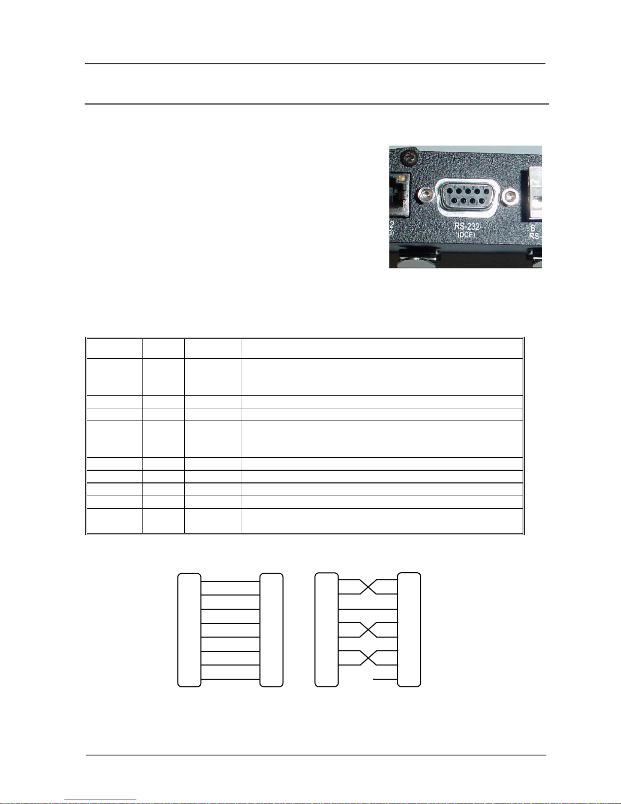
2.4 Serial Connections
2.4.1 RS232 Serial Port
The serial port is a 9 pin DB9 female and provides for
connection to a host device as well as a PC terminal for
configuration, field testing and for factory testing.
Communication is via standard RS232 signals. The 455U-D
is configured as DCE equipment with the pinout detailed
below. Hardware handshaking using the CTS/RTS lines is
provided. The CTS/RTS lines can be configured to reflect
the status of the local unit’s input buffer. The 455U-D
supports XON/XOFF flow control.
Example cable drawings for connection to a DTE host (a PC) or another DCE host (or modem)
is detailed below.
DB9 Connector Pinout
Pin
Name
Direction
Function
1
DCD
Out
Data carrier detect –
- driven when link is established in Acknowledged mode
- driven when module is online in unacknowledged mode
2
RD
Out
Transmit Data from modem – Serial Data Output
3
TD
In
Receive Data into modem – Serial Data Input
4
DTR
In
Data Terminal Ready - DTR can be configured to initiate low
power mode, or to force a link disconnection (“hang up” in
Acknowledged mode.
5
SG
Signal Ground
6
DSR
Out
Data Set Ready - always high when unit is powered on.
7
RTS
In
Request to Send - hardware flow control configurable
8
CTS
Out
Clear to send - hardware flow control configurable
9
RI
Out
Ring indicator - indicates another module is attempting to connect
in Acknowledged mode.
 Loading...