

Eaton 415U-2-C Instruction Leaflet
Surge Arrestor
(recommended)
Instruction Leaflet IL032054EN
Effective November 2017
415U-2-C wireless mesh networking I/O and
gateway installation guide
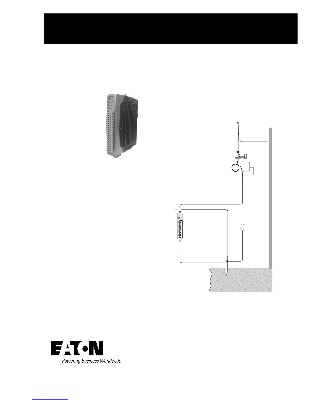
Antenna installation
When selecting an antenna, consider radio proximity.
Use Figure 1 as a guide for installing an antenna and attaching it
to the 415U-2-C.
Figure 1. Antenna installation
Wavelength:
340MHz = 35” (88cm)
400MHz = 30” (75cm)
480MHz = 25” (63cm)
Connect Coax to
building earth in
accordance with
6.2 g) and 6.2 i) of
IEC60728-11:2005
Coaxial Cable
Stress
Relief
Loop
Antenna
*
1 Wavelength
(minimum)
Weatherproof
Connections
(recommended:
3M™ 23 selfbonding tape)
GND
415U-2
GND
at least 11 AWG (4 mm2)
Provide good ground
connection to mast,
module, and surge
arrestor.
If ground conditions
are poor, use more
than one stake.
Earth Stake
Mast
Earth Conductor
at least 5 AWG
(16 mm2)
For maximum
*
range, install
above local
obstructions.
Connecting to the module for configuration
•
Download and install configuration application “CConfig”
from EATON website www.eaton.com/wireless
•
Connect to PC using supplied USB cable
•
Connect to the device at 192.168.111.1
•
Username: user
Password: user
Or 1.1.1.1 (firmware v2.4)
The PC will be automatically assigned an IP address via
DHCP
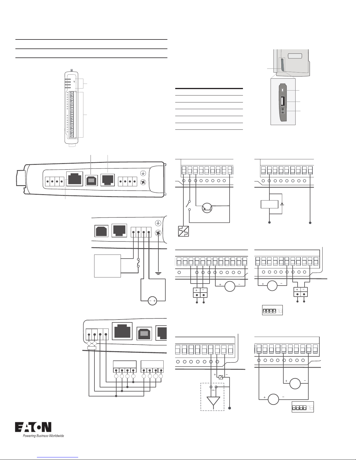
Instruction Leaflet IL032054EN
PWR
RF
232
485
LED Indicator
Lights
I/O Connectors
+24V
DC Load
+ –
D1 D3 D4 D5 D6 D7 D8
GND +24V
D2
mA
Loop-Powered
Sensor
Exernally
Powered
Sensor
Power Supply
GND +24V
AI1+AI1_AI2+AI2
_
AI3 AI4
AO1+AO2
+
GND +24V
mA
Loop-Powered
Sensor
Power Supply
Externally
Powered
Sensor
DIP Switch Setting
for Current IP
AI1+AI1_AI2+AI2
_
AI3 AI4
AO1+AO2
+
GND +24V
1 2 3 4 5 6
ON
for Voltage IP
RS232
USB RS232 SUPPLY
+
-
GND
BAT SUP
SUP
+
15-30 Vdc
Supply
3A Fuse
Optional
10.8–15 Vdc
Lead Acid
Battery
–
+
USB Host
Factory Boot
Switch
Configuration
Switches
Side
Access
Panel
Effective November 2017
415U-2-C wireless mesh networking I/O and gateway installation guide
NOTE
All connections must be SELV <50Vac and <60Vdc.
The following illustrations show the ports on the 415U2-C.
USB Port RS-232 Port
SUP
BAT SUP
GND
B A
+
-
ETHERNET USB RS232 SUPPLY
RJ-45 Ethernet Port
(connects to hub or switch)
+
-
Configuration switches
Use the DIP switches in the
side access panel to select
analog input voltage and
current, external boot, and
default configuration settings.
DIP DESCRIPTION
1 AI3 current/voltage
2 AI3 current/voltage
3 AI4 current/voltage
4 AI4 current/voltage
5 Unused
6 Enables default configuration
Input and output connections
The digital input/output channels can be wired as inputs or outputs.
Digital input Digital output
D1 D3 D4 D5 D6 D7 D8
D2
+
Transistor
Switch
Device
GND
Power supply wiring
The ground (GND) and “SUP–“
terminals are connected
internally to the ground terminal
and to the module enclosure.
Connect the screw terminal on
the end plate to ground for surge
protection.
Refer to user manual for RF duty
cycle derating when powering
the module from SUP+ and SUPterminals.
Expansion I/O power
and RS‑485 serial
B A
+
-
connection
An on-board RS-485
terminating resistor provides
line termination for long runs.
Enable terminating resistors
at far end of the RS-485
cable.
B A
RS-485
Eaton
1000 Eaton Boulevard
Cleveland, OH 44122
United States
Eaton.com
Eaton’s wireless business
www.eaton.com/wireless
B A B A
ETHERNET
115S-xx 115S-xx
USB
+
-
Voltage-free Contact
TTL CMOS
Output
Differential current inputs (Al1, Al2) Single-ended current input (Al3, Al4)
Analog output Single-ended voltage input
_
AI3 AI4
AO1+AO2
AI
+
COM
GND +24V
AI1_AI2+AI2
+
-
AI1+AI1_AI2+AI2
0–25V
Sensor
V
PLC
© 2017 Eaton
All Rights Reserved
Printed in USA
Publication No. IL032054EN
November 2017
Eaton is a registered trademark.
All other trademarks are property
of their respective owners.
AO1+AO2
_
AI3 AI4
0–5 Vdc
Sensor
V
ON
1 2 3 4 5 6
DIP Switch Setting
+
GND +24V
 Loading...