

Eaton 1MM, 37MM, 3MM, 35SS, 35MM Installation Instructions Manual
...
Installation Instructions for Type 1MM, 3MM, 35MM, 37MM,
35SS, and 37SS Modular Metering Centers
DANGER
H A Z A R D O U S V O LTA G E . W I L L C AUSE
SEV ER E I NJURY O R D EATH .
Tur n OFF pow er su ppl ying t his e qui pm en t bef ore wo rk in g
in sid e.
TEN SI ON DA N GER EU SE. PEU T CA USE R
DES BLE SSUR ES GR AV ES OU LA MO RT.
Co uper l ’al ime nt ati on é le ct ri que d e cet é qui pe me nt av ant
d’ y e ffe ctuer des trava ux.
)
PELIGRO
VO LTAJE PE LI GRO S O. CA USA HE RID AS
SEV ER AS O M UE RTE .
IN TER RUM PA el su min ist ro de e ner gia que a lim enta es te
e qu ip o an te s d e tr ab aj ar en e l in te ri or de l mi sm o.
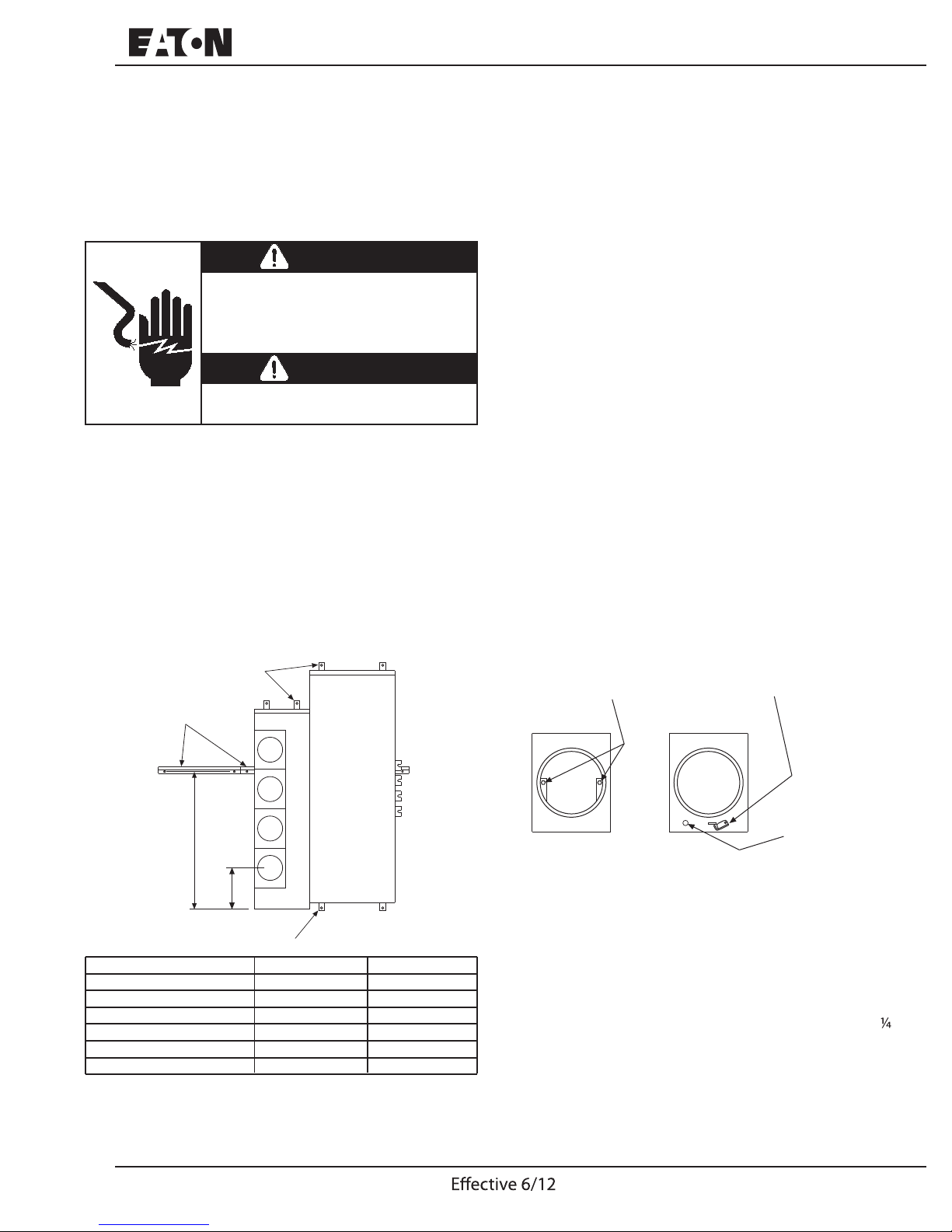
INSTALL MOUNTING RAILS ON WALL:
Establish the required height of the centerline of the bottom
meter socket, per the utility company specifications.
Determine the bottom line of the meter modules and main
devices. Use a “Z” dimension per the table below. That
is the distance from the bottom meter socket line to the
bottom of a meter module.
Measure up a distance “X” (see table) inches from the
bottom line of the meter modules to mounting holes for the
mounting rail. Strike a level line for the fasteners and attach
the mounting rails. (See Fig. 1 below).
MOUNTING FEET
MOUNTING RAIL(S)
MAIN DEVICE
Please read these instructions completely before installing
or removing device. Improper installation could be
hazardous to personnel and/or equipment.
Por favor lea estas instrucciones en su totalidad antes de
instalar o mover el aparato. Una instalacion inapropiada
puede ser peligrosa para el personal y/o el equipo.
Veuillez lire les présentes directives au complet avant
d’installer ou de retirer le dispositif. Une mauvaise installation
pourait causer des blessures au personnel et/ou
endommager l’equipement.
MOUNTING FEET:
Swivel the mounting feet at the top and bottom of the enclosures as shown (meter modules have two mounting feet
and main devices have four mounting feet). After marking
holes on the wall, the mounting feet may be moved away
for drilling of the holes. (See Fig. 1 below).
METER SOCKET COVERS:
Remove all the meter socket covers which are over the
horizontal main bus. Ring style covers are attached with
two screws inside the socket rim. Ringless style covers
are attached with an external movable latch. (See Fig. 2).
Ringless style covers have barrel lock provision K.O. To
use, remove knockout and apply kit 3MMBLKIT or 37MMBLK.
METER COVER
SCREWS
MOVABLE LATCH
“X”
“Z”
MOUNTING FEET
TYPE OF METER MODULE
1MM, 3MM - 125 AMP
1MM, 3MM - 200 AMP
35SS, 37SS - 1 METER
35SS, 37SS - 2,3 METER
35MM, 37MM - 1,3,4 METER
35MM, 37MM - 2 METER
“X” in.(mm)
34-7/32 (869.16)
34-7/32 (869.16)
17-1/16 (433.39)
35-3/16 (893.76)
30-11/16 (779.46)
30-11/16 (779.46)
Fig. 1 Locations of Mounting Feet, Rails, and Modules
I.L. 70-8306
“Z” in.(mm)
12-19/32 (319.88)
18-15/32 (469.11)
19-27/32 (504.03)
18-1/2 (469.90)
13 (330.20)
27 (685.80)
RING STYLE
COVER
RINGLESS STYLE
COVER
Fig. 2 Ring Type and Ringless Covers
METER MODULES:
Hang meter modules on the mounting rails, loosen all of
the main bus joint bolts, and slide the meter modules
together.
Fasten the enclosures together, in order to bond devices
together and provide suitable ground path, with the (2) # 20 screws supplied with each module.
Torque to 26 lb-in (2.94 N-m).
Torque each main bus joint bolt to 300 lb-in (33.90 N-m).
Secure mounting feet to the wall. (See Fig. 3 on Page 2).
1
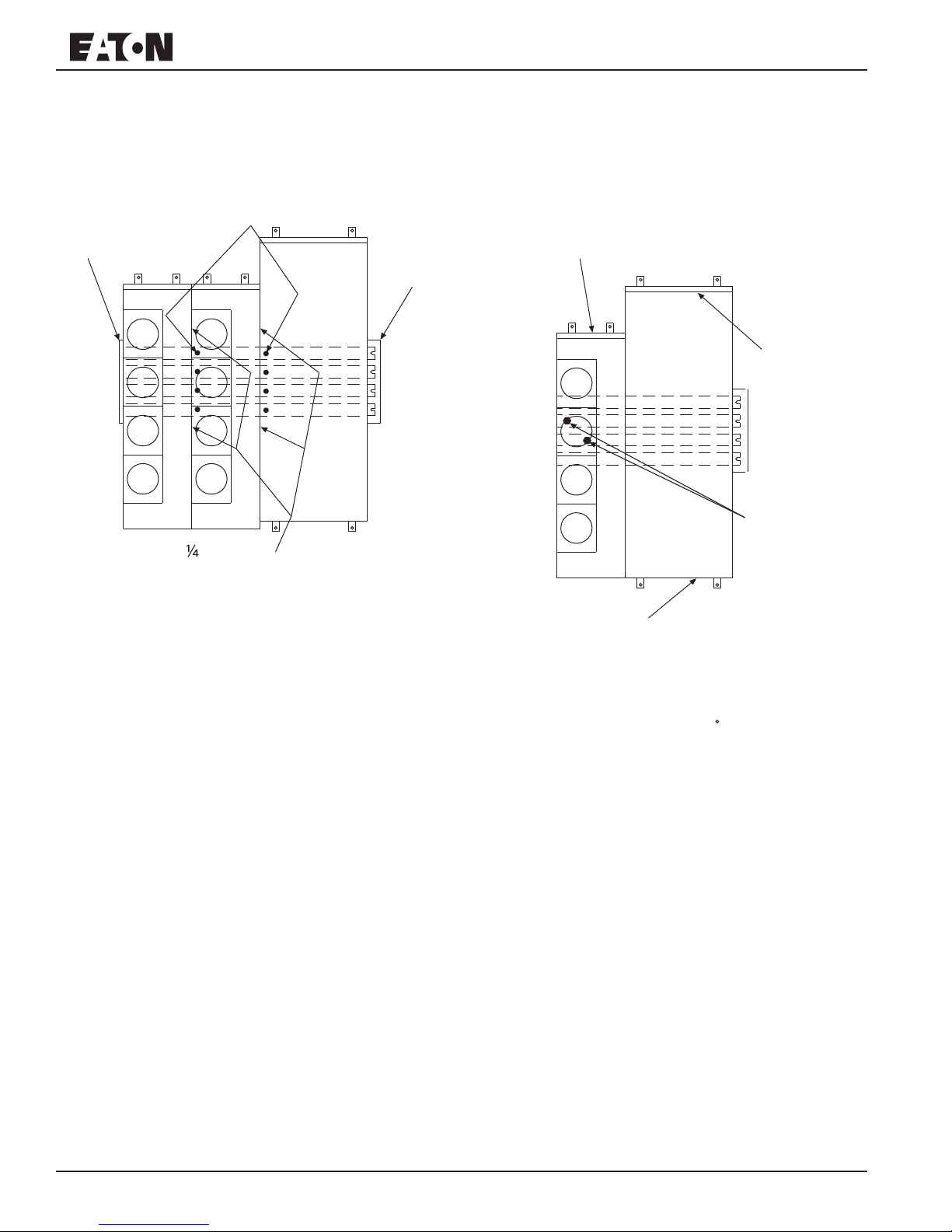
BUS END CAPS:
Install the bus end caps on the left hand side of the far left
meter module in the assembly and the far right meter
module in the assembly. End caps are supplied on the
main switch, main circuit breaker, or main terminal box
(one flush cap and one extended cap). (See Fig. 3 below).
MAIN BUS
FLUSH
END CAP
JOINT BOLTS
MAIN
DEVICE
EXTENDED
END CAP
PROVISIONS FOR HUBS OR KNOCKOUTS (CONT’D):
- Bottom Connection (1MM & 3MM)
Indoor and outdoor applications use knockouts that are
provided in bottom of meter modules or main devices.
- Bottom Connection (35MM, 37MM, 35SS, 37SS)
Indoor and outdoor applications use knockouts that are
provided in bottom of meter modules or main devices.
TOP KNOCKOUT PLATE
OR RAINTIGHT PLATE
MAIN
DEVICE
RAINTIGHT
PLATE
PHASE
CONNECTORS
#
-20 SCREWS
Fig. 3 Meter Module Assembly and End Cap Locations
PROVISIONS FOR HUBS OR KNOCKOUTS:
- Top Connections - Outdoor Application (1MM & 3MM)
Knockouts are not provided in top endwall. Punch proper
holes as required. Install raintight hubs on outdoor
devices.
- Top Connections - Indoor Application (1MM & 3MM)
Use the knockouts in top of module as required.
- Top Connections - Indoor or Outdoor Applications
(35MM, 37MM, 35SS, 37SS)
Remove raintight plate and punch proper holes for
installing raintight hubs. Reinstall raintight plate and
install raintight hubs into the raintight plate.
- Top Connections - Indoor or Outdoor Applications
(MTB, MFS, MCB, MHCB, or BPS)
Knockouts are not provided in top endwall. Punch proper
holes as required. Install raintight hubs on outdoor
devices.
- Backwall Connection (1MM & 3MM)
Knockouts are provided in Meter Modules. Remove
selected knockouts and pull wire through knockout
openings.
- Backwall Connection (35MM, 37MM, 35SS, 37SS)
Knockouts are provided in Meter Modules. Remove
selected knockouts and pull wire through knockout
openings.
BOTTOM
KNOCKOUT
PLATE
Fig. 4 Knockout Locations and Phase Connections
PHASE BALANCING, 3 PHASE SYSTEM (3MM ONLY):
Phase connectors are factory installed on the A Phase &
B Phase bus. Remove appropriate phase connectors and
balance for Phase A-B, B-C, or A-C, as needed, across
several meter modules in a complete installation. Torque
all phase connectors to 60 lb-in (6.78 N-m). (See Fig. 4
above).
INSTALL AND WIRE TENANT CIRCUIT BREAKERS:
Use only the circuit breakers listed on the meter module.
Check amperage and interrupting capacity for the
application.
TESTING AND INSPECTION:
- Recheck all main bus joint bolts for tightness. Torque to
300 lb-in. (33.90 N-m).
- Recheck all phase connectors for tightness. Torque to
60 lb-in. (6.78 N-m) minimum.
- Check all wire and cable terminations for proper installation
and tightness of lugs.
- Clean interiors of all units to remove foreign construction
material.
- Reinstall all meter socket covers and tenant breaker
covers.
2
I.L. 70-8306
 Loading...