

Eaton 380 VCP-WR 16, 380 VCP-W 25, 380 VCP-WR 32, 380 VCP-W 21, 380 VCP-WR 21 Instructions For Installation, Operation And Maintenance
...
I.B. 3A74792H08
Instructions for Installation, Operation and Maintenance
of Type VCP-W and VCP-WR 38kV Vacuum Circuit Breakers
Type VCP-W (Drawout)
Effective September 2014
Type VCP-W (Fixed)

I.B. 3A74792H08 Page iii
WARNING
IMPROPERLY INSTALLING OR MAINTAINING
THESE PRODUCTS CAN RESULT IN DEATH,
SERIOUS PERSONAL INJURY, OR PROPERTY
DAMAGE.
READ AND UNDERSTAND THESE INSTRUCTIONS
BEFORE ATTEMPTING ANY UNPACKING,
ASSEMBLY, OPERATION OR MAINTENANCE OF
THE CIRCUIT BREAKERS.
INSTALLATION OR MAINTENANCE SHOULD BE
ATTEMPTED ONLY BY QUALIFIED PERSONNEL.
THIS INSTRUCTION BOOK SHOULD NOT BE
CONSIDERED ALL INCLUSIVE REGARDING
INSTALLATION OR MAINTENANCE
PROCEDURES. IF FURTHER INFORMATION IS
REQUIRED, YOU SHOULD CONTACT EATON.
Eaton Corporation
Moon Township, PA. 15108
WARNING
THE CIRCUIT BREAKER ELEMENTS DESCRIBED
IN THIS BOOK ARE DESIGNED AND TESTED TO
OPERATE WITHIN THEIR NAMEPLATE RATINGS.
OPERATION OUTSIDE OF THESE RATINGS MAY
CAUSE THE EQUIPMENT TO FAIL, RESULTING IN
DEATH, BODILY INJURY AND PROPERTY
DAMAGE.
ALL SAFETY CODES, SAFETY STANDARDS
AND/OR REGULATIONS AS THEY MAY BE
APPLIED TO THIS TYPE OF EQUIPMENT MUST BE
STRICTLY ADHERED TO.
THE FIXED CIRCUIT BREAKER ELEMENTS ARE
DESIGNED TO BE INSTALLED PURSUANT TO
ALL APPLICABLE ANSI STANDARDS. SERIOUS
INJURY, INCLUDING DEATH, CAN RESULT FROM
FAILURE TO FOLLOW PROCEDURES OUTLINED
IN THIS MANUAL, OR COMPLY WITH THE
REQUIREMENTS OF APPLICABLE STANDARDS.
THE CUSTOMER IS RESPONSIBLE FOR
PROVIDING ALL REQUIRED PHASE TO PHASE
INSULATION, PHASE TO GROUND INSULATION
AND ALL BREAKER INTERLOCKS. THESE
CIRCUIT BREAKER ELEMENTS ARE SOLD
PURSUANT TO A NON-STANDARD PURCHASING
AGREEMENT WHICH LIMITS THE LIABILITY OF
THE MANUFACTURER.
Al l possible contingencies which may arise during installation, operation or maintenance, and all details
and variations of this equipment do not purport to be covered by these instructions. If further information
is desired by purchaser regarding his particular installation, operation or maintenance of particular
equipment, contact a Eaton representative.
Effective 09/2014

Page iv I.B. 3A74792H08
TABLE OF CONTENTS
SECTION 1: INTRODUCTION Page
1-1 Preliminary Comments and Safety Precautions .......................................................................................... 1
1-1.1 Warranty and Liability Information ...................................................................................................... 1
1-1.2 Safety Precautions ............................................................................................................................. 1
1-2 General Information ..................................................................................................................................... 1
1-3 Type VCP-W and VCP-WC Vacuum Circuit Breaker Ratings .................................................................... 2
1-4 Outlines and Dimensions ............................................................................................................................. 6
SECTION 2: SAFE PRACTICES
2-1 Recommendations .................................................................................................................................... 8
SECTION 2: RECEIVING, HANDLING AND STORAGE
3-1 General ........................................................................................................................................................ 9
3-2 Receiving ..................................................................................................................................................... 9
3-3 Handling ....................................................................................................................................................... 9
3-4 Storage ...................................................................................................................................................... 10
3-5 Tools and Accessories .............................................................................................................................. 11
3-6 Type VCP-W and VCP-WR Vacuum Circuit Breaker Weights .................................................................. 11
SECTION 4: INITIAL IN SPE CT ION AND IN STA LLATI ON
4-1 Introduction ................................................................................................................................................ 17
4-2 Manual Operation Check ........................................................................................................................... 17
4-3 Vacuum Interrupter Integrity ...................................................................................................................... 17
4-4 Insulation ................................................................................................................................................... 17
4-5 Contact Erosion and Wipe ......................................................................................................................... 17
4-6 Primary Circuit Resistance ........................................................................................................................ 17
4-7 Nameplate ................................................................................................................................................. 17
4-8 Electrical Operation Check ........................................................................................................................ 17
4-8.1 Circuit Breaker Insertion and Removal .................................................................................... 18
4-8.2 Operation Check Performance ................................................................................................ 19
4-9 Breaker/Structure Interfacing ..................................................................................................................... 19
4-9.1 Interface Interlocks .................................................................................................................. 19
4-9.2 Drawout Breaker Interfacing Check (VCP-W) ......................................................................... 19
SECTION 5: DESCRIPTION AND OPERATION
5-1 Introduction ................................................................................................................................................ 21
5-2 Interrupter Assembly.................................................................................................................................. 21
5-2.1 Vacuum Interrupter .................................................................................................................. 22
5-2.2 Contact Erosion Indication ....................................................................................................... 22
5-2.3 Loading Spring Indication ........................................................................................................ 23
5-2.4 Contact Wipe and Stroke .................................................................................................
5-3 Stored Energy Mechanism ........................................................................................................................ 23
........ 23
Effective 09/2014

I.B. 3A74792H08 Page v
Page
5-3.1 Operation of Stored Energy Mechanism ..................................................................................... 23
5-3.2 Charging ....................................................................................................................................... 23
5-3.3 Closing Operation ................................................................................................................... 25
5-3.4 Tripping Operation .................................................................................................................. 25
5-4 Control Schemes ................................................................................................................................. 25
5-4.1 Timing ..................................................................................................................................... 25
5-4.2 Secondary Disconnects .......................................................................................................... 25
5-4.3 Secondary Terminal Blocks .................................................................................................... 29
5-4.4 Undervoltage Trip Device........................................................................................................ 29
5-5 Interlocks and Interfacing .................................................................................................................... 30
5-6 Levering Mechanism (VCP-W Only) .................................................................................................... 30
5-7 Operations Counter ............................................................................................................................. 30
5-8 Ground Contact ................................................................................................................................... 30
5-9 MOC and TOC Switch Operations ....................................................................................................... 30
SECTION 6: INSPECTION, MAINTENANCE AND TROUBLESHOOTING
6-1 Introduction ......................................................................................................................................... 32
6-2 Frequency of Inspection and Maintenance .......................................................................................... 32
6-2.1 Qualified Personnel ............................................................................................................... 32
6-2.2 Helpful Tools and Accessory Items ....................................................................................... 32
6-2.3 General Torque Guidelines ................................................................................................... 32
6-3 Inspection and Maintenance Procedures ............................................................................................. 35
6-4 Vacuum Interrupter Integrity Test ........................................................................................................ 36
6-5 Contact Erosion ................................................................................................................................... 36
6-6 Contact Wipe ....................................................................................................................................... 36
6-7 Insulation ............................................................................................................................................. 37
6-8 Insulation Integrity Check .................................................................................................................... 37
6-9 Primary Circuit Resistance Check ....................................................................................................... 37
6-10 Mechanism Check ............................................................................................................................... 39
6-10.1 CloSure
6-11 Lubrication ........................................................................................................................................... 43
6-12 Troubleshooting Chart ......................................................................................................................... 43
SECTION 7: RENEWAL PARTS
7-1 General .............................................................................................................................................. 46
7-1.1 Ordering Instructions ............................................................................................................. 46
Figure Title Page
1-1 Type VCP-W 38kV Drawout Circuit Breaker Outlines and Dimensions ................................................. 6
1-2 Type VCP-WR 38kV Fixed Circuit Breaker Outlines and Dimensions ................................................... 7
3-1 Circuit Breaker Shown Mounted with Ramp Still in Shipping Position (VCP-W Only) .......................... 10
3-2 Circuit Breaker Shown Being Moved Carefully Down Attached Ramp (VCP-W Only) ......................... 10
3-3 Optional Fifth Wheel Shown in Use (VCP-W Only) .............................................................................. 10
3-4 Front View VCP-W 38kV Drawout Vacuum Circuit Breaker ................................................................. 12
3-5 VCP-W or VCP-WR 38kV Vacuum Circuit Breaker with Front Cover Removed .................................. 13
3-6 Rear View VCP-W 38kV Drawout Vacuum Circuit Breaker ................................................................. 14
3-7 Rear View VCP-WR Fixed Vacuum Circuit Breaker ............................................................................ 15
Effective 09/2014
TM
Test ...................................................................................................................... 39
FIGURES

Page vi I.B. 3A74792H08
FIGURES
Figure Title Page
3-8 Typical VCP-W 38kV Escutcheon ............................................................................................................. 16
4-1 Type VCP-W Circuit Breaker Manual Charging Handle in Use ................................................................ 18
4-2 Drawout Circuit Breaker (Bottom View) ..................................................................................................... 20
5-1 Rear View Showing Pole Unit Enclosure (VCP-W Only) ........................................................................... 21
5-2 Plate Over Rear Truck Opening 2000A Breakers and Above (VCP-W Shown) ....................................... 21
5-3 Graphic Representation of Arc Interruption ............................................................................................... 22
5-4 Closing Cam and Trip Linkage .................................................................................................................. 24
5-5 Charging Schematic .................................................................................................................................. 26
5-6 Typical VCP-W “DC” and “AC” Control Schematics (Drawout) ................................................................. 27
5-7 Typical VCP-WR “DC” and “AC” Control Schematics (Fixed) ................................................................... 28
5-8 Secondary Plug Shown Mounted Lower Left Drawout Circuit Breaker ..................................................... 29
5-9 Secondary Terminal Blocks Shown Mounted Bottom Front Fixed Circuit Breaker ................................... 30
5-10 Undervoltage Trip Device Configuration .................................................................................................... 31
6-1 Lubrication Points (Drawout Circuit Breaker Shown) ................................................................................ 34
6-2 Rear Measurement for Contact Erosion Being Made (Circuit Breaker Closed) ........................................ 37
6-3 Graphical Representation of Contact Erosion Measurement .................................................................... 37
6-4 Side View of Loading Spring Indicator (Circuit Breaker Closed) ............................................................... 38
6-5 Graphical Representation of Contact Wipe Measurement of Loading Spring Indicator ............................ 38
6-6 Resistance Measurement Locations ......................................................................................................... 38
6-7 Status Indicators ........................................................................................................................................ 39
6-8 Starting Tape at Bottom ............................................................................................................................. 39
6-9 Wrapping Tape up around Cam ................................................................................................................ 39
6-10 Attaching Tape Around to Back of Cam .................................................................................................... 40
6-11 Attaching CloSure
6-12 Attaching CloSure
6-13 Manually Charging Closing Springs .......................................................................................................... 40
6-14 Manually Closing Circuit Breaker with Marker in Hole “C” ........................................................................ 41
6-15 Top View of Cam and Marker Interface ..................................................................................................... 41
6-16 Move Marker 15° to Right .......................................................................................................................... 41
6-17 Move Marker 15° to Left ............................................................................................................................ 41
6-18 Remove Marked Masking Tape from Cam ................................................................................................ 41
6-19 Place Tape on Right Side Panel of Breaker .............................................................................................. 41
6-20 Illustrative Testing Tape Sample ............................................................................................................... 42
6-21 Front View of CloSure
6-22 Typical Circuit Breaker Front View with CloSure
Table Title Page
1-1 Type VCP-W Ratings on Symmetrical Current Rating Basis ...................................................................... 2
1-2 Type VCP-WC Ratings on Symmetrical Current Rating Basis ................................................................... 4
3-1 Approximate Circuit Breaker Weights ........................................................................................................ 11
5-1 Circuit Breaker Timing ............................................................................................................................... 29
6-1 Torque Guidelines ..................................................................................................................................... 33
6-2 Test Voltage ............................................................................................................................................... 36
6-3 CloSure
TM
Tool Mounting /Testing Locations by Circuit Breaker Type ..................................................... 42
6-4 Approximate Resistance Measurements ................................................................................................... 43
7-1 Recommended Renewal Parts for ANSI Rated Breakers ......................................................................... 46
TM
Test Tool at Hole “A” ................................................................................................ 40
TM
Test Tool at H Pole “B” ............................................................................................. 40
TM
Tool Showing Mounting/Testing Hole Locations ................................................ 42
TM
Tool Attached ............................................................ 42
TABLES
Effective 09/2014
I.B. 3A74792H08 Page 1
SECTION 1: INTRODUCTION
1-1 PRELIMINARY COMMENTS AND SAFETY PRECAUTIONS
This technical document is intended to cover most
aspects associated with the installation, application,
operation and maintenance of the VCP-W and VCP-WR
Vacuum Circuit Breakers. It is provided as a guide for
authorized and qualified personnel only. Please refer to
the specific WARNING and CAUTION in Section 1-1.2
before proceeding. If further information is required by
the purchaser regarding a particular installation,
application or maintenance activity, a Eaton
representative should be contacted.
1-1.1 WARRANTY AND LIABILITY
IN FORMATION
NO WARRANTIES, EXPRESSED OR IMPLIED,
INCLUDING WARRANTIES OF FITNESS FOR A
PARTICULAR PURPOSE OF MERCHANTABILITY, OR
WARRANTIES ARISING FROM COURSE OF DEALING
OR USAGE OF TRADE, ARE MADE REGARDING THE
INFORMATION, RECOMMENDATIONS AND
DESCRIPTIONS CONTAINED HEREIN. In no event will
Eaton be responsible to the purchaser or user in
contract, in tort (including negligence), strict liability or
otherwise for any special, indirect, incidental or
consequential damage or loss whatsoever, including but
not limited to damage or loss of use of equipment, plant
or power system, cost of capital, loss of power, additional
expenses in the use of existing power facilities, or claims
against the purchaser or user by its customers resulting
from the use of the information and descriptions
contained herein.
1-1.2 SAFETY PRECAUTIONS
All safety codes, safety standards and/or regulations
must be strictly observed in the installation, operation
and maintenance of this device.
ING IS SHOWN ABOVE IN REVERSE TYPE TO
FAMILIARIZE PERSONNEL WITH THE STYLE OF
PRESENTATION. THIS WILL HELP TO INSURE THAT
PERSONNEL ARE ALERT TO WARNINGS, WHICH
MAY APPEAR THROUGHOUT THE DOCUMENT. IN
ADDITION, CAUTIONS ARE ALL UPPER CASE AND
BOLDFACE AS SHOWN BELOW.
CAUTION
COMPLETELY READ AND UNDERSTAND THE
MATERIAL PRESENTED IN THIS DOCUMENT
BEFORE ATTEMPTING INSTALLATION, OPERATION
OR APPLICATION OF THE EQUIPMENT. IN
ADDITION, ONLY QUALIFIED PERSONS SHOULD BE
PERMIT-TED TO PERFORM ANY WORK
ASSOCIATED WITH THE EQUIPMENT. ANY WIRING
INSTRUCTIONS PRESENTED IN THIS DOCUMENT
MUST BE FOLLOWED PRECISELY. FAILURE TO DO
SO COULD CAUSE PERMANENT EQUIPMENT
DAMAGE.
1-2 GENERAL INFORMATION
The purpose of this book is to provide instructions for
unpacking, storage, use, operation and maintenance of
Type VCP-W Drawout and Type VCP-WR Fixed 38kV
Vacuum Circuit Breakers. They are similar in many ways
with the main differences centering around the
secondary/primary connection methods and the mounting
methods used. The differences are specifically addressed
in this book. The Type VCP-W is a horizontal drawout, roll
on the floor type removable interrupter element. The
Type VCP-WR is a fixed interrupter element with the
customer responsible for all required operational and
safety interfaces. Designed to ANSI Standards for
reliable performance, ease of handling, and simplified
maintenance, VCP-W and VCP-WR circuit breakers
provide reliable control and protection for electrical
equipment and circuits. In addition, these technologically
advanced circuit breakers provide higher insulation levels
in less space, thus reducing the overall switchgear size.
WARNING
THE WARNINGS AND CAUTIONS INCLUDED AS
PART OF THE PROCEDURAL STEPS IN THIS
DOCUMENT ARE FOR PERSONNEL SAFETY AND
PROTECTION OF EQUIPMENT FROM DAMAGE. AN
EXAMPLE OF A TYPICAL WARNING LABEL HEAD-
Effective 09/2014
WARNING
SATISFACTORY PERFORMANCE OF THESE
BREAKERS IS CONTINGENT UPON PROPER
APPLICATION, CORRECT INSTALLATION AND
ADEQUATE MAINTENANCE. THIS INSTRUCTION
BOOK MUST BE CAREFULLY READ AND
FOLLOWED IN ORDER TO OBTAIN OPTIMUM
PERFORMANCE FOR LONG USEFUL LIFE OF THE
CIRCUIT BREAKERS.
Page 2 I.B . 3A74792H08
A
A
WARNING
THE CIRCUIT BREAKERS DESCRIBED IN THIS
BOOK ARE DESIGNED AND TESTED TO OPERATE
WITHIN THEIR NAMEPLATE RATINGS. OPERATION
EQUIPMENT TO FAIL, RESULTING IN DEATH,
BODILY INJURY AND PROPERTY DAMAGE.
ALL SAFETY CODES, SAFETY STANDARDS AND/OR
REGULATIONS AS THEY MAY BE APPLIED TO THIS
TYPE OF EQUIPMENT MUST BE STRICTLY
ADHERED TO.
OUTSIDE OF THESE RATINGS MAY CAUSE THE
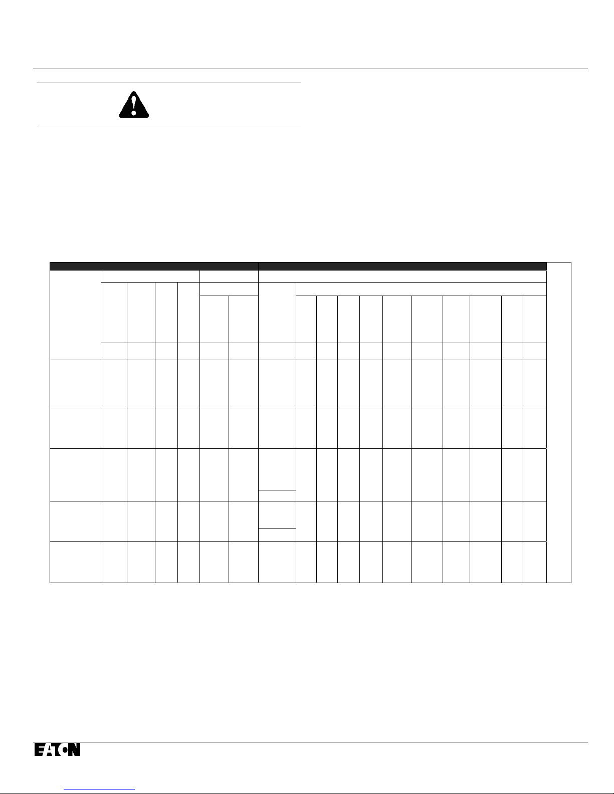
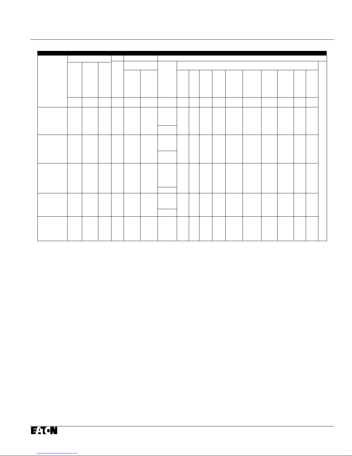
1-3 TYPE VCP-W AND VCP-WC VACUUM CIRCUIT BREAKER RATINGS (TABLES 1.1 AND 1.2)
Table 1.1 Type VCP-W Ratings on Symmetrical Current Rating Basis
Identification Rated Values
Circuit
Breaker
Type
380 VCP-W 16
and
380 VCP-WR 16
380 VCP-W 25
and
380 VCP-WR 25
380 VCP-W 32
and
380 VCP-WR 32
380 VCP-W 21
and
380 VCP-WR 21
380 VCP-W 40
and
380 VCP-WR 40
Nominal
Voltage
Class
kV rms kV rms kV rms kV rms kV Peak Amperes rms kA rms %
34.5 38 1 38 80 170
34.5 38 1 38 80 170
34.5 38 1 38 80 170
34.5 38
34.5 38 1 38 80 170
Voltage Insulation Level Current
Voltage
Maximum
Voltage
V
Range
Factor
K
1.65
V/K
23
Power
Frequency
(1 Minute)
Withstand Test
Lightning
Impulse
1 .2x50 µs
80 170
Continuous
Current
at 60 Hz
600
1200
1600
2000
600
1200
1600
2000
600
1200
1600
2000
3000FC
2500
1200
2000
3000FC
2500
1200
2000
3000FC
2500
Sym.
Inter-
rupting
ponent
at V
(Isc)
16 47 1.2 19.2 16 19.3 43 26 16 3
25 47 1.2 30.0 25 30.0 68 40 25 3
31.5 47 1.2 37.8 31.5 37.8 85 50 31.5 3
21 47 1.2 39.5
40 47 1.2 48.0 40 48.0 107 63 40 3
% dc
Com-
(Idc)
sym.
Factor
S
(ref.)
Short Circuit Current
sym.
Max. Sym.
Inter-
Inter-
rupting
rupting
(It)
at V/K
(KxIsc)
kA rms
Total kA rms
35
Max. Asym.
(SxKxIsc)
Closing
Inter-
rupting
at V/K
and
Latching
Capability
Momentary
Withstand
Capability
Current
Short
Time
Current
kA rms
Total kA Peak
42.0 95 56 35 3
kA rms
Total kA rms s
KEMA tested to applicable standards ANSI C37.04 - 1979, C3 7.09 - 1979, C37.06 - 1997 (ope rating Duty Seque nce CO - 15s - CO). Typical operating time values: opening 45 ms, closing 75 ms, and reclosing 300 ms
(18 cycles).
K=1 .0, therefore E=E/K and I=KI, refer to the Consulting Application Catalog for further information.
Rated and Tested also for Rapid Re-closing Capability O - 0.3s - CO.
Not rated for Rapid Re-closing.
At 23kV rms (Rated Max Voltage/K), Rated maximum symmetrical interrupting capability = 35kA rms (K x I).
For Force Air Cooled Fixed Breaker Applications, consult Eaton.
The ANSI C37.06 Standard requires 150kV BIL. If higher BIL levels are required, please refer to the “C” breakers.
If you require 50 ms (3 cycle) interrupting time, please refer to the “C” breakers.
The Standard Breaker is not rated for capacitor switching. If you require capacitor switching, please refer to the “C” breakers.
Duration
of
Short
Time
Current
T ►
A
B
L
E
C
O
N
T
I
N
U
E
D
F
R
O
M
N
E
X
T
P
A
G
E ►
Effective 09/2014
I.B. 3A74792H08 Page 3
Table 1.1 Type VCP-W Ratings (continued from previous page)
Rate
◄T
A
B
L
E
C
O
N
T
I
N
U
E
D
F
R
O
M
P
R
E
V
I
O
U
S
P
A
G
◄E
Values
Operating Duty
(Duty Cycle)
CO - 15s - CO 100 83 5 2 0.6 2000
CO - 15s - CO 100 83 5 2 0.6 2000
CO - 15s - CO 100
CO - 15s - CO
CO - 15s - CO
CO - 15s - CO
Rated
Reclosing
Factor R
Interrupting
Time
% ms Cycles Seconds kV/µs
83
—
83
100
—
Maximum
Transient
Permissible
Recovery
Tripping
Delay
5
2
5
2
Mechanical
Voltage
Endurance
(RRRV)
No-Load
Operations
0.6 2000
0.6 2000
CO - 15s - CO
83 5 2 0.6 2000
—
Effective 09/2014
Page 4 I.B. 3A74792H08
A
A
A
A
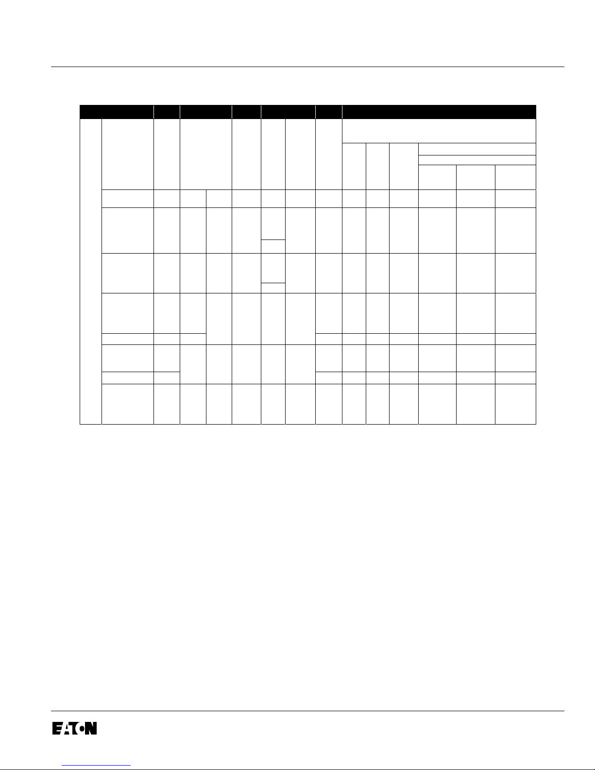
Table 1.2 Type VCP-WC Ratings on Symmetrical Current Rating Basis
Identification Rated Values
Circuit
Breaker
Type
380 VCP-W 16C
and
380 VCP-WR 1 6C
380 VCP-W 25C
and
380 VCP-WR 25C
380 VCP-W 32C
and
380 VCP-WR 32C
380 VCP-W 21 C
and
380 VCP-WR 21C
380 VCP-W 40C
and
380 VCP-WR 40C
KEMA tested to applicable standards ANSI C37.04 - 1979, C37.09 - 1979, C37.06 - 1997 (operat ing Duty Seque nce CO - 1 5s - CO). Typical operating time values: opening 45 ms, closing 75 ms, and reclosing
300 ms (18 cycles).
K=1 .0, therefore E=E/K and I=KI, refer to the Consulting Application Catalog for further information.
Rated and Tested also for Rapid Re-closing Capability O - 0.3s - CO.
Not rated for Rapid Re-closing.
At 23kV rms (Rated Max Voltage/K), Rated maximum symmetrical interrupting capability = 35kA rms (K x I).
For Force Air Cooled Fixed Breaker Applications, consult Eaton.
Voltage
Nominal
Maximum
Voltage
V
Voltage
Factor
Voltage
Class
kV rms kV rms kV rms kV rms kV Peak Amperes rms kA rms %
34.5 38 1 38 80 170
34.5 38 1 38 80 170
34.5 38 1 38 80 170
34.5 38
34.5 38 1 38 80 170
Range
K
1.65
Insulation Level Current
Withstand Test
V/K
23
Power
Frequency
(1 Minute)
Impulse
1 .2x50 µs
80 170
Lightning
Continuous
Current
at 60 Hz
600
1200
1600
2000
600
1200
1600
2000
600
1200
1600
2000
3000FC
2500
1200
2000
3000FC
2500
1200
2000
3000FC
2500
Sym.
% dc
Com-
ponent
(Idc)
sym.
Factor
S
(ref.)
rupting
kA rms
Inter-
Total kA rms
Inter-
rupting
at V
(Isc)
16 75 1.46 23.3 16 23.3 50 30 16 3.09
25 65 1.36 34.0 25 34.0 75 44 25 3.09
33.1 57 1.28 42.5 33.1 42.5 91 54 31.5 3.09
21 52 1.24 26.1
40 63 1.34 53.5 40 53.5 107 65 40 3.04
sym.
(It)
Short Circuit Current
Max. Sym.
Max. Asym.
Inter-
rupting
at V/K
(KxIsc)
35
Closing
Inter-
rupting
at V/K
(SxKxIsc)
kA rms
Total kA Peak
43.4 102 60 35 3.21
and
Latching
Capability
Momentary
Withstand
Capability
Short
Current
Time
Current
kA rms
Total kA rms
Duration
of
Short
T►
B
L
E
C
O
N
T
I
N
U
E
D
F
R
O
M
N
E
X
T
P
G
E►
Effective 09/2014
I.B. 3A74792H08 Page 5
Table 1.2 Type VCP-WC Ratings (continued from previous page)
Rated Values
◄ T
A
Operating Duty
B
(Duty Cycle)
L
E
C
O
N
T
I
N
CO - 15s - CO
U
E
D
F
CO - 15s - CO 100 50 3 2
R
O
M
N
CO - 15s - CO
E
X
T
CO - 15s - CO
P
CO - 15s - CO 100
A
G
CO - 15s - CO
◄ E
CO - 15s - CO
Capacitor Switching Rating
Maximum
Tripping
Delay
2
2
Transient
Recovery
Voltage
(RRRV)
0.7
1.3
0.7
1.3
0.7
0.7
0.7
1.3
1.3
0.7
0.7
1.3
1.3
0.7
Rated
Reclosing
Factor R
Interrupting
Time
% ms Cycles Seconds kV/µs
100 50 3 2
100 50
—
—
—
— — 53 — — — —
50
50 3 2 0.7 15000 — — 53 — — — —
3
3
Permissible
Mechanical
Endurance
Operations kA rms A rms A rms A rms A rms kA Peak kHz
No-Load
15000
15000
15000
15000
Out-of-
Phase
Overhead
Switching
Line
Current
8.4
8.4
8.4
8.3
8.4
8.4
8.4
8.3
8.4
8.4
8.4
8.3
8.3
8.4
8.3
8.3
— — 53 — — — —
Charging
Current
5 56
5 56
5 53
5 53
Cable
Current
Isolated
Shunt
Capacitor
Bank
Current
250
250
250
250 & 1000
250
250
250
250 & 1000
250
250
250
250 & 1000
250 & 1000
250
250 & 1000
250 & 1000
Definite Purpose
Back to Back Capacitor Switching
Bank
Inrush
Current
20
20
20
20 & 20
20
20
20
20 & 20
20
20
20
20 & 20
20 & 20
20
20 & 20
20 & 20
Capacitor
Current
250
250
250
250 & 1000
250
250
250
250 & 1000
250
250
250
250 & 1000
250 & 1000
250
250 & 1000
250 & 1000
Inrush
Frequency
4.4
4.4
4.4
5 & 5
4.4
4.4
4.4
5 & 5
4.4
4.4
4.4
5 & 5
5 & 5
4.4
5 & 5
5 & 5
Effective 09/2014
Page 6
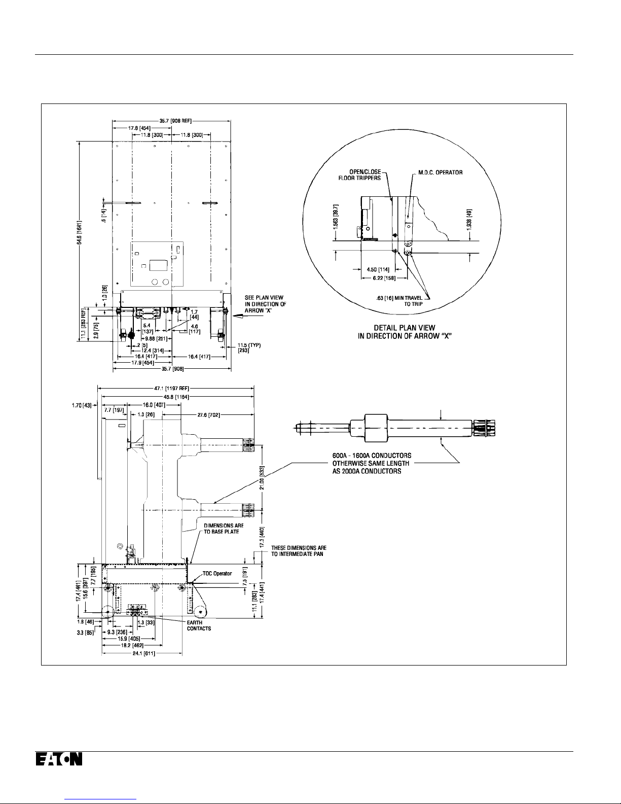
1-4 OUTLINES AND DIMENSIONS
I.B. 3A74792H08
Figure 1-1 Type VCP- W 38kV Drawout Circuit Breaker Outlines and Dimensions (inches and [mm])
Effective 09/2014
I.B. 3A74792H08 Page 7
Effective 09/2014
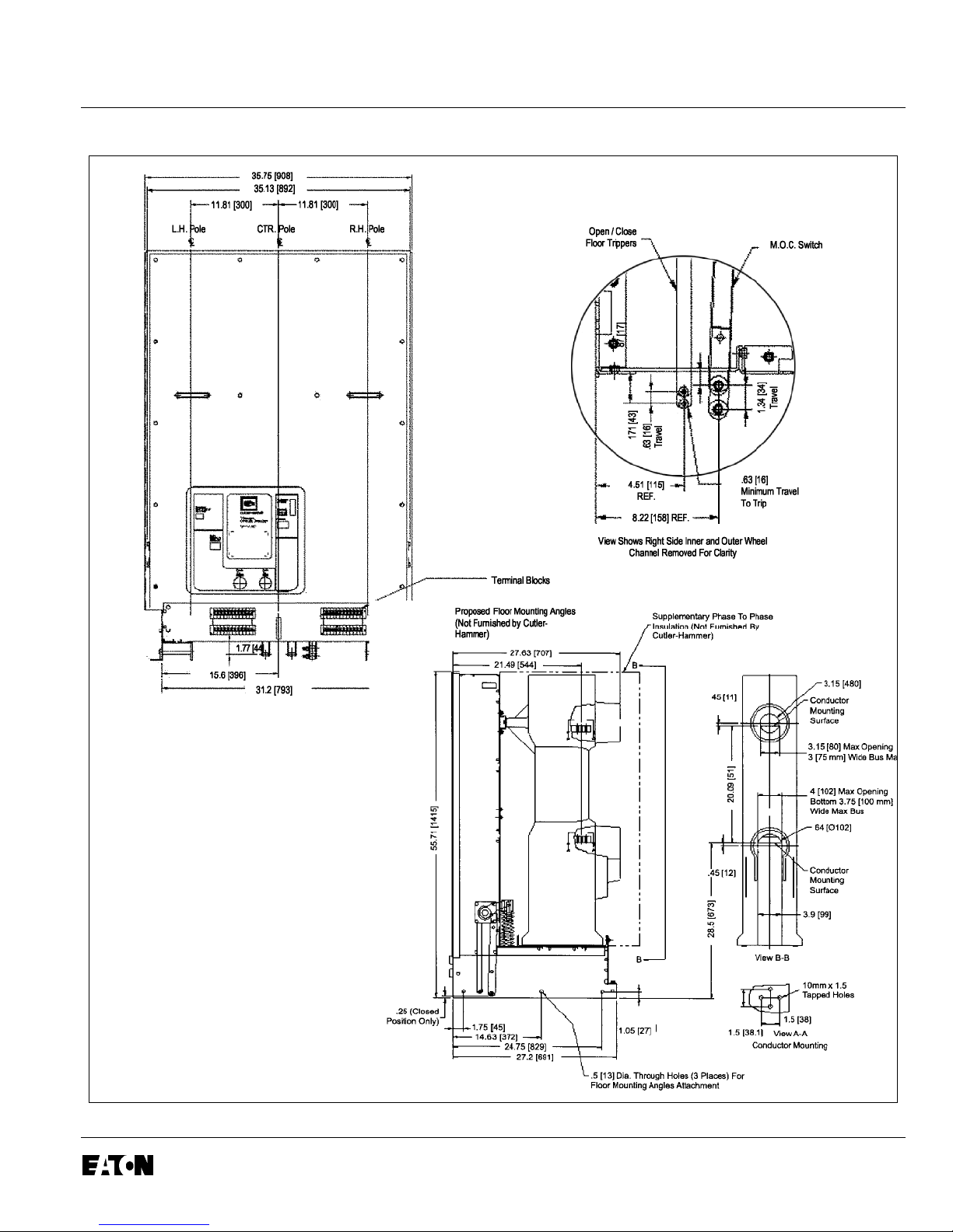
Page 8 I. B. 3A74792H08
Figure 1-2 Type VCP- WR 38kV Fixed Circuit Breaker Outlines and Dimensions (inches and [mm])
SECTION 2: SAFE PRACTICES
2-1 RECOMMENDATIONS
Type VCP-W and VCP-WR Vacuum Circuit Breakers are
equipped with high speed, high energy operating
mechanisms. They are designed with several built-in
interlocks and safety features to provide safe and proper
operating sequences. Cell interlocks used with drawout
circuit breakers are meant to interact with the appropriate
cell interface and levering mechanism.
WARNING
TO PROTECT THE PERSONNEL ASSOCIATED WITH
INSTALLATION, OPERATION, AND MAINTENANCE
OF THESE CIRCUIT BREAKERS, THE FOLLOWING
PRACTICES MUST BE FOLLOWED:
Only qualified persons, as defined in the National
Electrical Safety Code, who are familiar with the
installation and maintenance of medium voltage
circuits and equipment, should be permitted to work on
these circuit breakers.
Read these instructions carefully before attempting any
installation, operation or maintenance of these circuit
breakers.
If the final breaker design is drawout, always remove
the breaker from the enclosure before performing any
maintenance. If the breaker is applied in a fixed configuration, always make sure that primary and
secondary power are disconnected from the breaker.
Failure to do so could result in electrical shock leading to
death, severe personal injury or property damage.
Do not work on a drawout circuit breaker with a
secondary test coupler engaged. Failure to
disconnect the test coupler could result in an
electrical shock leading to death, personal injury
or property damage.
Do not work on a closed circuit breaker or a
breaker with closing springs charged. The closing
springs should be discharged and the main circuit
contacts open before working on the circuit
breaker. Failure to do so could result in cutting or
crushing injuries.
Do not use an open circuit breaker by itself as the
sole means of isolating a high voltage circuit.
Remove the circuit breaker to the Disconnect
position and follow all lock-out and tagging rules of
the National Electrical Code and any other
applicable codes, regulations and work rules.
Do not leave a drawout circuit breaker in an
intermediate position in the cell. Always have the
circuit breaker either in the Disconnect/Test or
Connected position. Failure to do so could result in
a flash over and possible death, personal injury or
property damage.
• Always remove the maintenance tool from the
circuit breaker after charging the closing springs.
• Circuit breakers are equipped with safety
interlocks. Do Not remove, interfere with or in any
manner defeat them. This may result in death,
bodily injury or equipment damage.
Do not work on a circuit breaker suspended from a
lifting yoke or chains. Maintenance work should be
per-formed on a solid work surface, such as the
floor.
Effective 09/2014
I.B. 3A74792H08 Page 9
SECTION 3: RECEIVING, HANDLING AND
STORAGE
3-1 GENERAL
Type VCP-W and VCP-WR Vacuum Circuit Breakers
are subjected to complete factory production tests in
accordance with ANSI C37.09 and inspection before
being packed. They are shipped in packages designed
to provide maximum protection to the equipment during
shipment and storage and at the same time to provide
convenient handling. Tools and accessories, such as
the maintenance tool, are shipped separately.
3-2 RECEIVING
If the circuit breaker is not to be used immediately but is
to be placed in storage, maximum protection can be
obtained by keeping it packed as shipped.
Upon receipt of the equipment, inspect the containers
for any signs of damage or rough handling. Open the
containers carefully to avoid any damage to the contents. Use a nail puller rather than a crow bar when
required. When opening the containers, be careful to
save any loose items or hardware that may be otherwise discarded with the packing material. Check the
contents of each package against the packing list.
Examine the circuit breaker for any signs of shipping
damage such as broken, missing or loose hardware,
damaged or deformed insulation and other components.
File claims immediately with the carrier if damage or loss
is detected and notify the nearest Eaton Office.
NOTICE
The VCP-W and VCP-WR 38kV shipping container
and pallet were specifically designed to facilitate
removal of the circuit breaker from its pallet and
container. Before proceeding, installation personnel
should be familiar with the procedures outlined in
Paragraph 3-3 entitled “Handling.”
3-3 HANDLING
FOR OPENING, CLOSING THE CONTACTS OR
CHARGING THE SPRINGS. THE CIRCUIT BREAKER
MAY SLIP OR FALL CAUSING SEVERE PERSONAL
INJURY. ALWAYS PERFORM MAINTENANCE,
REPAIR AND ADJUSTMENTS ON A SOLID WORK
SURFACE CAPABLE OF SUPPORTING THE
CIRCUIT BREAKER.
VCP-W and VCP-WR 38kV Vacuum Circuit Breakers
are shipped mounted to a skid specially designed to
facilitate removal of the breaker. Refer to Figures 3-1
and 3-2 and proceed with the following steps:
WARNING
AFTER REMOVING THE BRACKETS USED TO
HOLD THE CIRCUIT BREAKER SECURELY TO
THE SHIPPING SKID AND ALL DURING THE
PROCESS OF MOVING THE CIRCUIT BREAKER
OFF OF THE SHIPPING SKID AND DOWN THE
RAMP TO THE FLOOR, TAKE SPECIAL
PRECAUTIONS TO INSURE THAT THE CIRCUIT
BREAKER IS MOVED SLOWLY AND UNDER
CONTROL TO AVOID ANY ACCIDENTS. THE
CIRCUIT BREAKER IS A LARGE DEVICE WHICH
COULD CAUSE SERIOUS BODILY INJURY IF IT IS
TIPPED OVER OR PERMITTED TO ROLL IN AN
UNCONTROLLED MANNER.
CAUTION
DO NOT PULL ON OR USE THE MAIN (PRIMARY)
CONDUCTORS AND OR THE PRIMARY
DISCONNECTS TO MANEUVER THE CIRCUIT
BREAKER IN ANY FASHION. FAILURE TO
COMPLY WITH THIS CAUTION COULD RESULT
IN SIGNIFICANT EQUIPMENT DAMAGE.
WARNING
DO NOT USE ANY LIFTING DEVICE AS A PLATFORM FOR PERFORMING MAINTENANCE, REPAIR
OR ADJUSTMENT OF THE CIRCUIT BREAKER OR
Effective 09/2014
Page 10 I.B. 3A74792H08
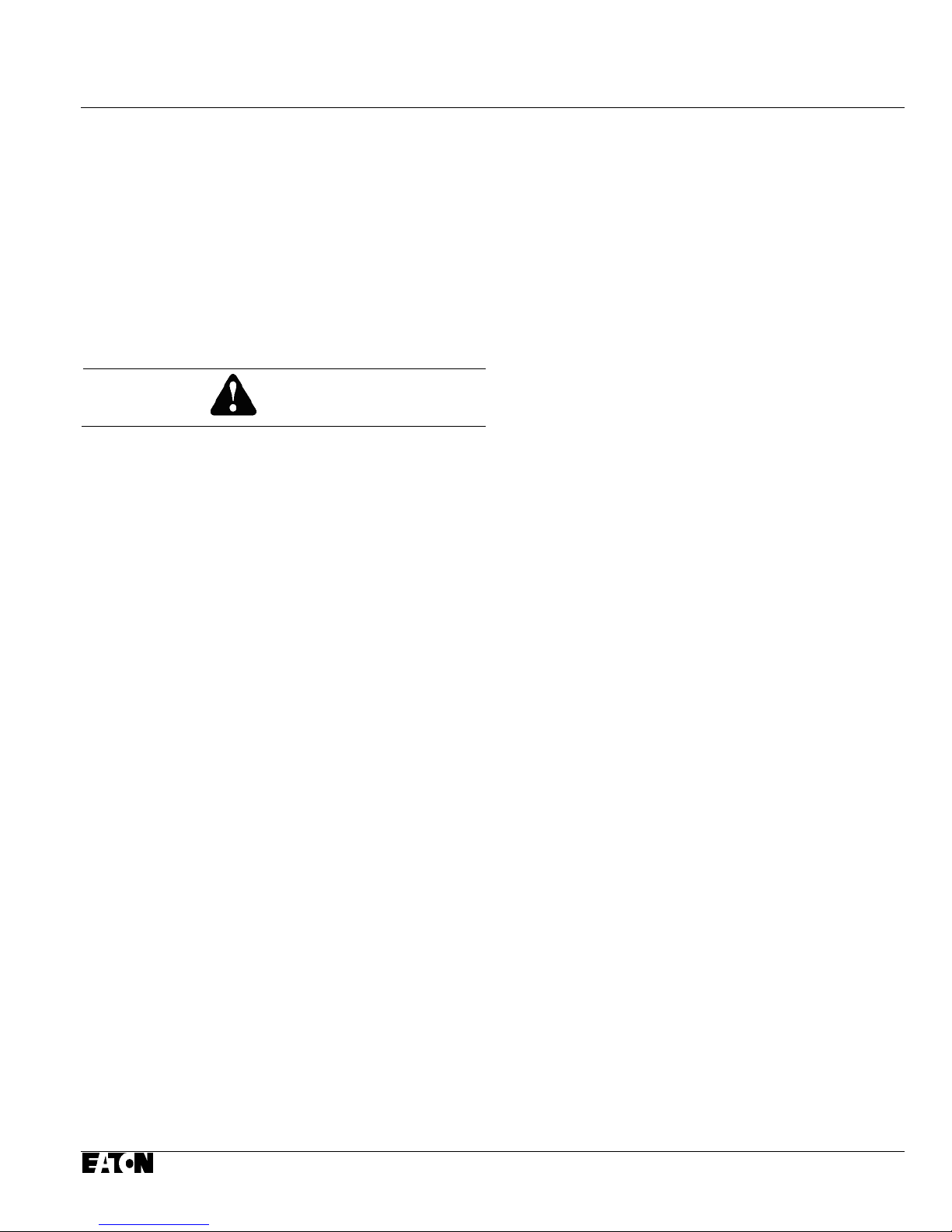
Figure 3-1 Circuit Breaker Shown Mounted with Ramp
Still in Shipping Position (VCP-W Only)
Step 1: VCP-WR breakers must be lifted from the
shipping pallet. Refer to paragraph 3-5 for
the optional lifting yoke used with an
overhead lifting device after all shipping
hardware used to hold the breaker to the
skid is removed.
Step 2: For VCP-W breakers, remove the vertically
mounted ramp from the shipping skid and
place it on the floor next to the skid. It
should be positioned with the highest part
of the ramp next to the side of the skid with
the front of the circuit breaker.
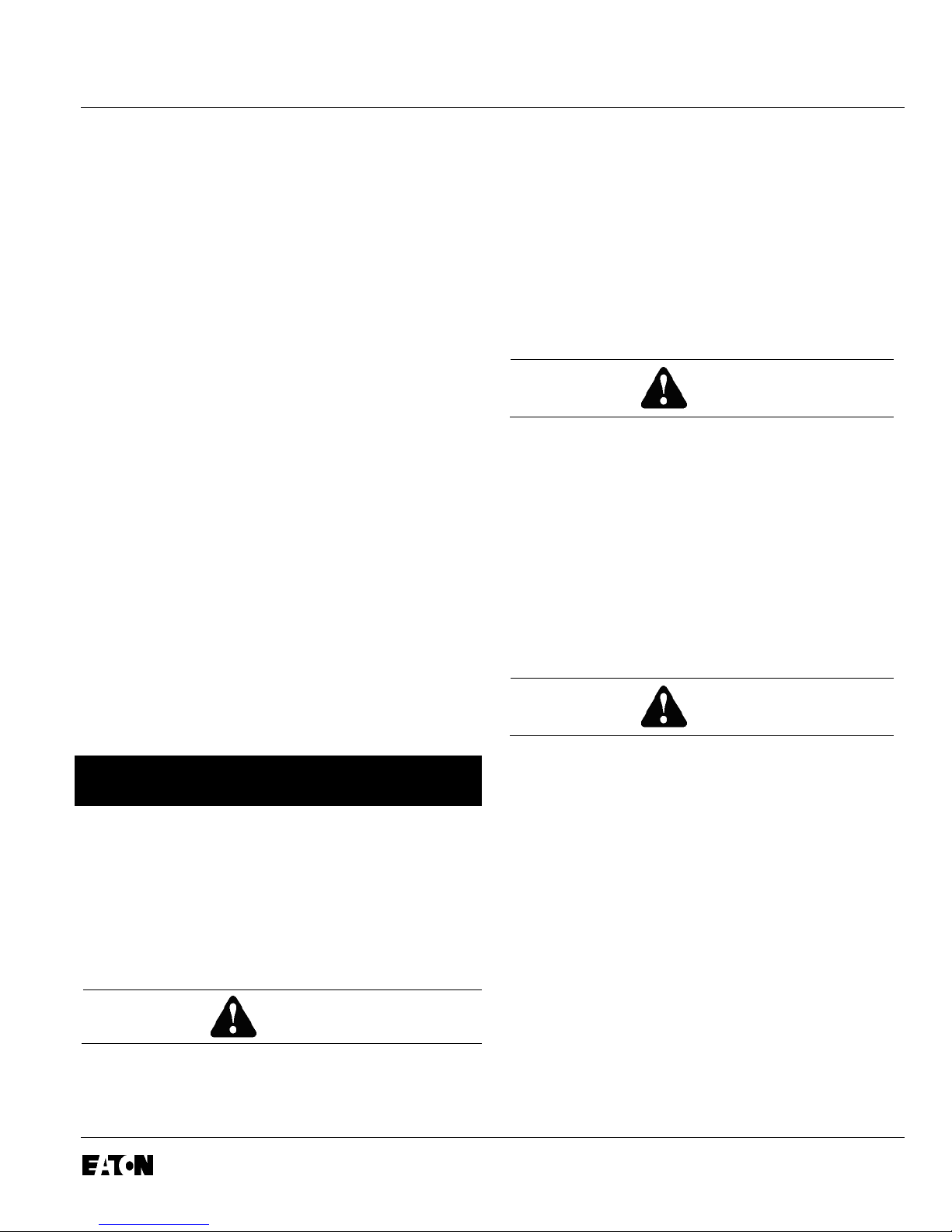
Step 3: Remove the shipping brackets used to hold
the circuit breaker to the skid. Use the
same shipping brackets and hardware to
attach the ramp to the shipping skid.
Step 4: Slowly move the circuit breaker forward and
down the ramp. Make certain that the
circuit breaker moves down the ramp
slowly and straight in line with the ramp.
Once the circuit breaker is on the floor, it
can be easily maneuvered via its integral
wheels.
VCP-W breakers can also be lifted using the
Figure 3-2 Circuit Breaker Shown Being Moved
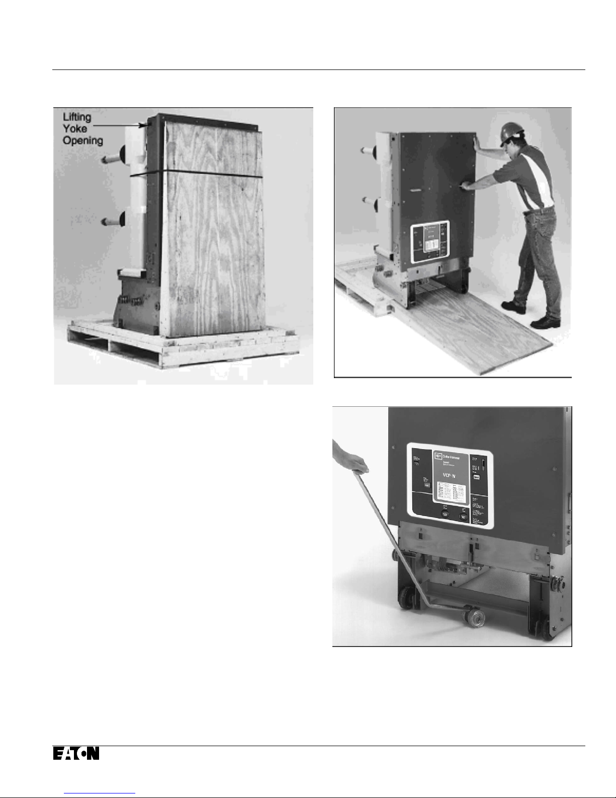
Figure 3-3 Optional Fifth Wheel Shown in
Use (VCP-W Only)
3.4 STORAGE
If the circuit breaker is to be placed in storage, maxi-
Effective 09/2014
I.B. 3A74792H08 Page 11
optional lifting yoke described in Step 1
mum protection can be obtained by keeping it packed as
shipped. Before placing it in storage, checks should be
made to make sure that the circuit breaker is free from
shipping damage and is in satisfactory operating
condition.
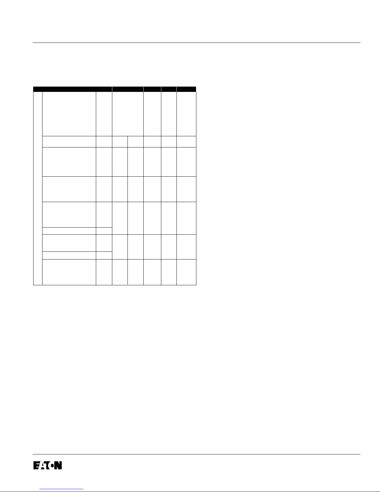
3-6 TYPE VCP-W AND VCP-WR VACUUM CIRCUIT
BREAKER WEIGHTS (TABLE 3.1)
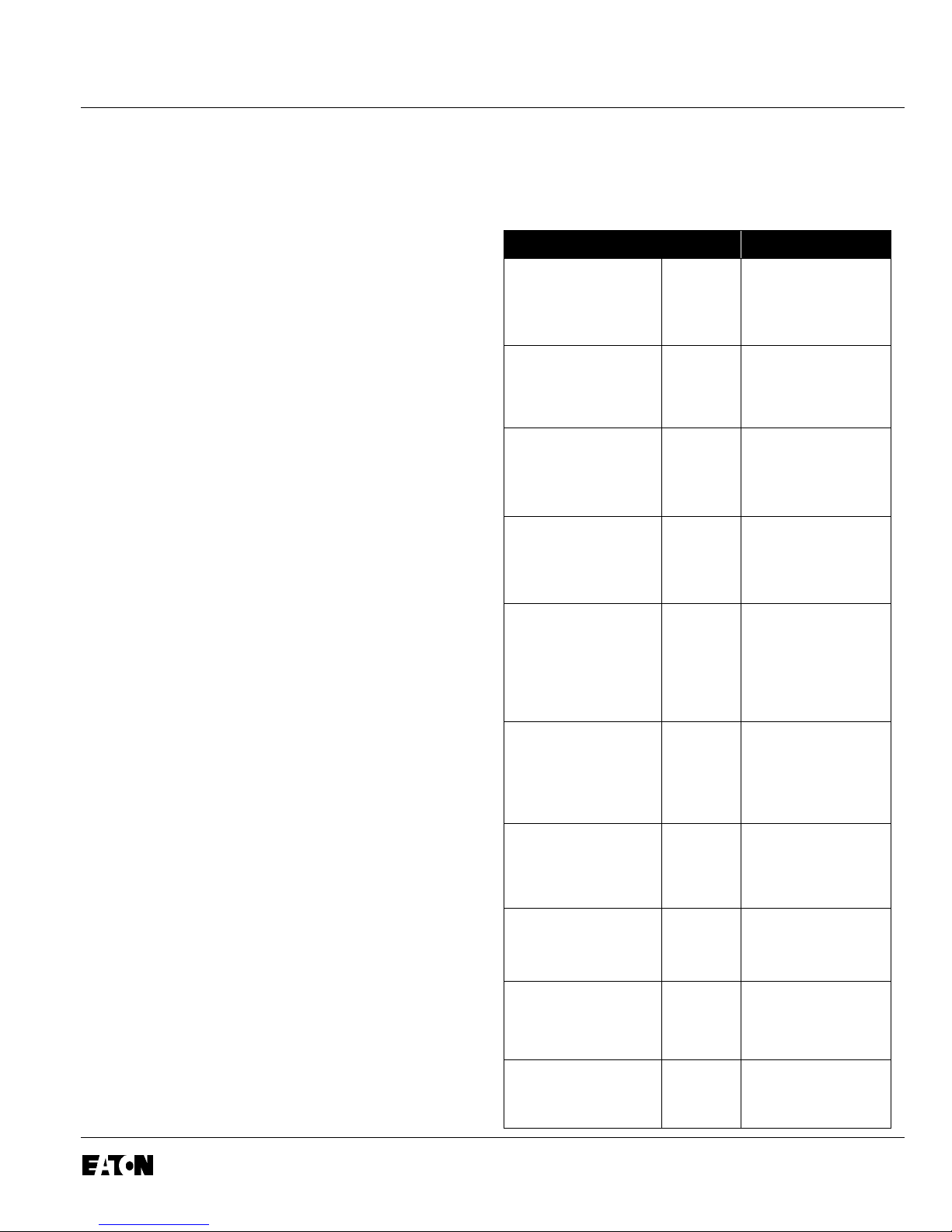
Table 3. 1 Approximate Circuit Breaker Weights
Rating Pounds
The circuit breaker is shipped with its contacts open and
closing springs discharged. The indicators on the front
panel should confirm this. Insert the maintenance tool in
the manual charge socket opening (Figure 3-8).
Charge the closing springs by pumping the handle up
and down approximately 38 times until a crisp metallic
“click” is heard. This indicates that the closing springs
are charged and is shown by the closing spring
“charged” (yellow) indicator. Remove the maintenance
tool. Push the “manual close” button. The circuit breaker
will close as shown by the circuit breaker contacts
“closed” (red) indicator. Push the “manual trip” button.
The circuit breaker will trip as shown by the circuit
breaker contacts “open” (green) indicator. After
completing this initial check, leave the closing springs
“discharged” and circuit breaker contacts “open”.
Outdoor storage is NOT recommended. If unavoidable,
the outdoor location must be well drained and a
temporary shelter from sun, rain, snow, corrosive
fumes, dirt, falling objects and excessive moisture must
be provided. Containers should be arranged to permit
free circulation of air on all sides and temporary
heaters should
be used to minimize condensation. Moisture can cause
rusting of metal parts and deterioration of high voltage
insulation. A heat level of approximately 400 watts for
each 100 cubic feet of volume is recommended with the
heaters distributed uniformly throughout the structure
near the floor.
Indoor storage should be in a building with sufficient
heat and air circulation to prevent condensation. If the
building is not heated, the same general rule for heat as
for outdoor storage should be applied.
380 VCP-W 16
&
380 VCP-W 16C
380 VCP-WR 16
&
380 VCP-WR 1 6C
380 VCP-W 25
&
380 VCP-W 25C
380 VCP-WR 25
&
380 VCP-WR 25C
380 VCP-W 32
&
380 VCP-W 32C
380 VCP-WR 32
&
380 VCP-WR 32C
380 VCP-W 21
&
380 VCP-W 21C
600
1200
1600
2000
600
1200
1600
2000
600
1200
1600
2000
600
1200
1600
2000
600
1200
1600
2000
2500
3000
600
1200
1600
2000
2500
1200
2000
2500
3000
1070
1080
1090
1140
937
948
958
1025
1070
1080
1090
1140
937
948
958
1025
1070
1080
1090
1140
1182
1182
937
948
958
1025
1064
1080
1140
1182
1182
3-5 TOOLS AND ACCESSORIES
Several tools and accessories, both standard and
optional are available for use with the circuit breaker.
Maintenance Tool (Standard): Used to charge closing
springs.
Lifting Yoke (Optional): Used to lift circuit breaker with
overhead lifting device.
Effective 09/2014
380 VCP-WR 21
&
380 VCP-WR 21 C
380 VCP-W 40
&
380 VCP-W 40C
380 VCP-WR 40
&
380 VCP-WR 40C
1200
2000
2500
1200
2000
2500
3000
1200
2000
2500
948
1025
1064
1182
1182
1182
1182
1064
1064
1064

Page 12 I.B. 3A74792H08
Does not include shipping carto n.
Fifth Wheel (Optional): Used to maneuver a circuit
breaker on a flat, hard surface (Figure 3-3).
Effective 09/2014

I.B. 3A74792H08 Page 13
Figure 3-4 Front View VCP-W 38kV Drawout Vacuum Circuit Breaker
Effective 09/2014
 Loading...