

Eaton 350 VA, 550 VA, 450 VA, 750 VA User Manual
Eaton 3S UPS (350–550 VA and 750 VA)
User's Guide
®
The Eaton 3S uninterruptible power system (UPS) protects your sensitive electronic
equipment from power problems such as power failures, power sags, and power
surges.
Features
Model 350 VA 450 VA 550 VA 750 VA
Battery Backup and Surge Protection Outlets 4 4 4 5
Surge Protection Only Outlets 4 4 4 5
EcoControl Funct ion
User-Replaceable Battery
Phone/Fax/DSL Sur ge Protection
USB Port
Cold Start Capability
IMPORTANT SAFETY INSTRUCTIONS
SAVE THESE INSTRUCTIONS
This user's guide contains important instructions that you s hould follow during
installation and maintenance of the UPS and batteries. Please read all instructions
before operating the equipment and save this user's guide for future reference.
When the Eaton 3S UPS is received, remove and inspect the product for shipping
damage. If any damage is found, notify the carrier and your dealer immediately.
Keep all shipping contents, including the shipping carton, packing material, and
packing slip, in the event that the UPS must be returned to the factory for service.
CAUTION Maintenance must be performed by a qualified personnel.
Failure to do so could result in an electric shock. Replace battery with an
Eaton supplied battery ONLY! Although the UPS may be unplugged from
the utility power, hazardous voltage still may be present through the
battery.
S Place the Eaton 3S UPS indoors in a n area that has adequate airflow and is free
from excessive dust. DO NOT allow the UPS to be exposed to moisture, rain,
excessive heat, or direct sunlight.
S Use of the Eaton 3S UPS product in life s upport applications where failure of this
equipment can reasonably be expected to cause failure of life support
equipment or to significantly affect its safety or effectiveness is NOT
recommended.
S Always turn off the UPS and disconnect the input power cord from the wall
outlet before replacing the battery.
S When replacing the battery, use the same number a nd type of battery.
S DO NOT d ispose of the battery in a fire, the battery may explode.
S DO NOT open or mutilate the battery. Batteries contain an electrolyte that is
toxic and harmful to both the skin and eyes.
S Proper disposal of the battery is required. Refer to your local laws/regulations
regarding battery recycling/reuse.
S Use tools with insulated handles to replace the battery to avoid personal injury.
Due to energy hazards, remove wristwatches and jewelry such as rings when
replacing the battery.
Package Contents
Verify the package contents:
S Eaton 3S UPS
S USB cable (450 VA, 550 VA, and 750 VA models only)
S This user's guide
S Warranty statement
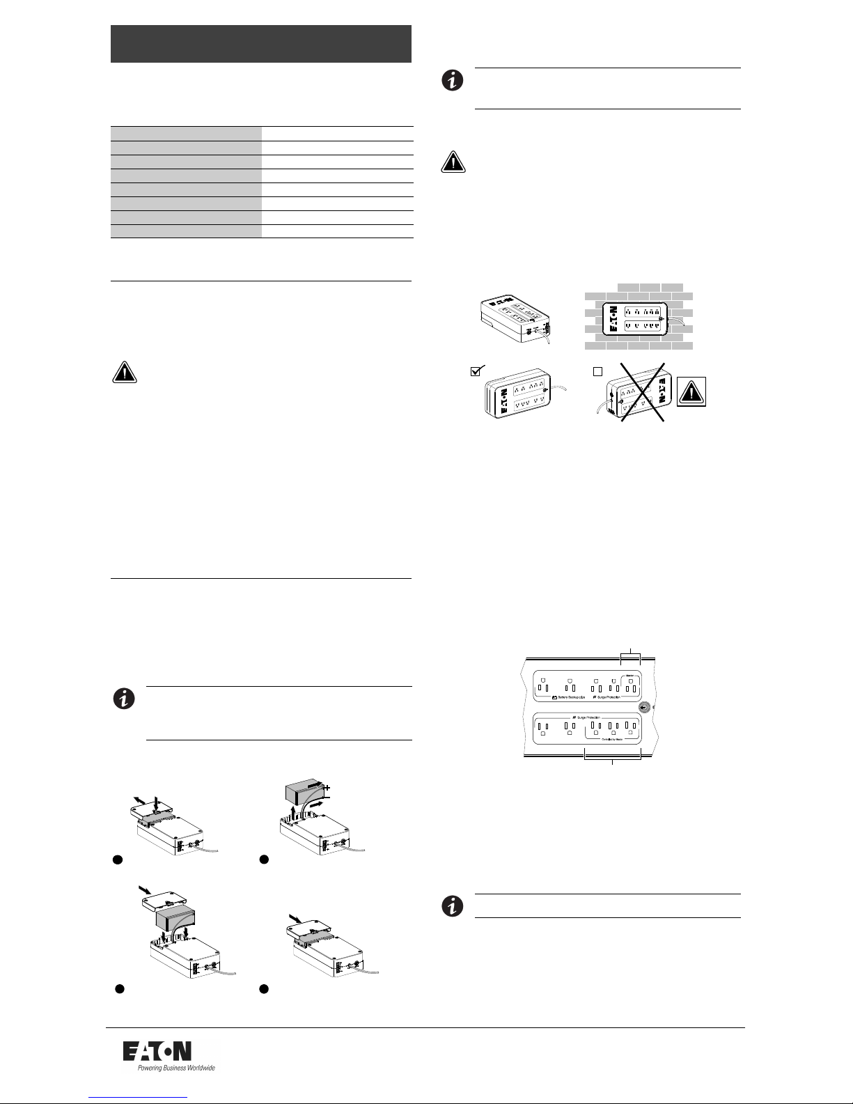
Connect Battery
NOTE Check the battery recharge date on the shipping carton label. If the date has
passed and the batteries were never recharged, do not use the UPS. Contact your
service representative.
NOTE If the UPS requires any type of transportation, the internal UPS battery MUST
be disconnected .
For safety, the UPS is shipped with the battery wires disconnected. The UPS will
not run until the wires are connected to the battery terminals.
1
Turn the UPS over and press in the
release tab. Slide the battery cover
off the UPS.
Pull out the battery and connect the
battery wires firmly to the battery
terminals; red to positive (+), black to
negative (–).
Insert the battery back into the
compartment.
2
3
Slide the battery cover on the UPS until
the release tab locks into place.
4
Connect Equipment
To connect and operate the Eaton 3S UPS:
1. Connect the UPS to a grounded power outlet.
NOTE Eaton recommends that the battery should be charged for a minimum of
eight hours to ensure full charge before placing the UPS in service. The UPS charges the
battery as soon as it is connected to the AC outlet, whether the On/Off button is pressed
or not.
2. Plug your computer, monitor, or load to be protected into the Battery Backup
and Surge Protection outlets. (These outlets provide emergency battery backup
power during power outages and protection from surges and spikes.)
CAUTION DO NOT plug laser printers or accessory surge strips into the
battery backup outlets.
3. Plug your peripheral equipment or non-critical loads (printer, scanner, fax,
speakers, etc.) into the Surge Protection outlets. (These outlets provide surge
and spike protection only, they DO NOT provide battery backup power during a
utility power failure).
4. 450 VA, 550 VA, and 750 VA models only. Connect your computer to the
UPS using the USB cable provided.
Installation Positions
The UPS can be free-standing or wall-mounted. For safety, do not place the UPS on
its right side.
Turn On the UPS and Install the Software
To turn the UPS on and install the power management software:
1. With your equipment turned off, press the UPS On/Off button. The UPS On/Off
button illuminates green.
2. Turn on the connected equipment.
3. 450 VA, 550 VA, and 750 VA models only. Go to
www.eaton.com/p owerquality to download and install Eaton's Personal
Solution-Pac
t power management software.
The Personal Solution-Pac software establishes communication between your
computer and UPS. The software allows you to change default UPS settings
and view information about the status of your utility power line.
4. Register your Eaton 3S UPS online at www.eaton.com/powerquality for an
extended warranty.
EcoControl Function (750 VA Model Only)
The EcoControl function is an energy-saving feature that can be enabled through
the Personal Solution-Pac software. When the EcoControl function is enabled, the
EcoControl outlets automatically power down when the load connected to the
Master outlet is turned off.
Master Outlet
EcoControl Outlets
Enable the EcoControl Function
The EcoControl function is disabled by default. The Personal Solution-Pac software
must be installed before the EcoControl function can be enabled. To enable the
EcoControl function:
1. From your Microsoft
®
Windows®Start menu, click All Programs > EATON >
Personal Solution Pac > Settings. The EATON Settings window opens.
2. Go to UPS Settings > EcoControl function > EcoControl function
activation. The EcoControl function activation panel displays.
3. Select EcoControl function activation.
4. Click Apply to activate, or click OK to activate and close the window.
NOTE When the EcoControl function is activated, do not connect critical applications
to the EcoControl outlets.
Set the EcoControl Function Threshold
The default trigger threshold (Medium) ensures the correct operation of the
EcoControl function for a typical load consumption on the Master outlet. If the load
consumption is outside of the default trigger threshold range, you can modify the
threshold. To modify the trigger threshold:
1. From your Microsoft Windows Start menu, click All Programs > EATON >
Personal Solution Pac > Settings. The EATON Settings window opens.
2. Confirm that the function is activated in the EcoControl function activation
panel.
Eaton is a registered trademark and Personal Solution-Pac is a trademark of Eaton Corporation or its subsidiaries and affiliates.
Microsoft and Windows are registered trademarks of Microsoft Corporation in the United States and/or other countries.
All other trademarks are property of their respective companies.
ECopyright 2010 Eaton Corporation, Raleigh, NC, USA. All rights reserved.
164202102 Rev P01
3. Select EcoControl function detection threshold. The EcoControl function
detection threshold panel displays.
4. If the peripherals connected to the EcoControl outlets do not turn off when the
load powered by the Master outlet is turned off or is in standby mode, set the
detection threshold value to High.
5. If the peripherals connected to the EcoControl outlets turn off when the load
powered by the Master outlet is working normally, set the detection threshold
value to Low.
6. Click Apply to activate, or click OK to activate and the c lose window.
7. Restart the load connected to the Master outlet.
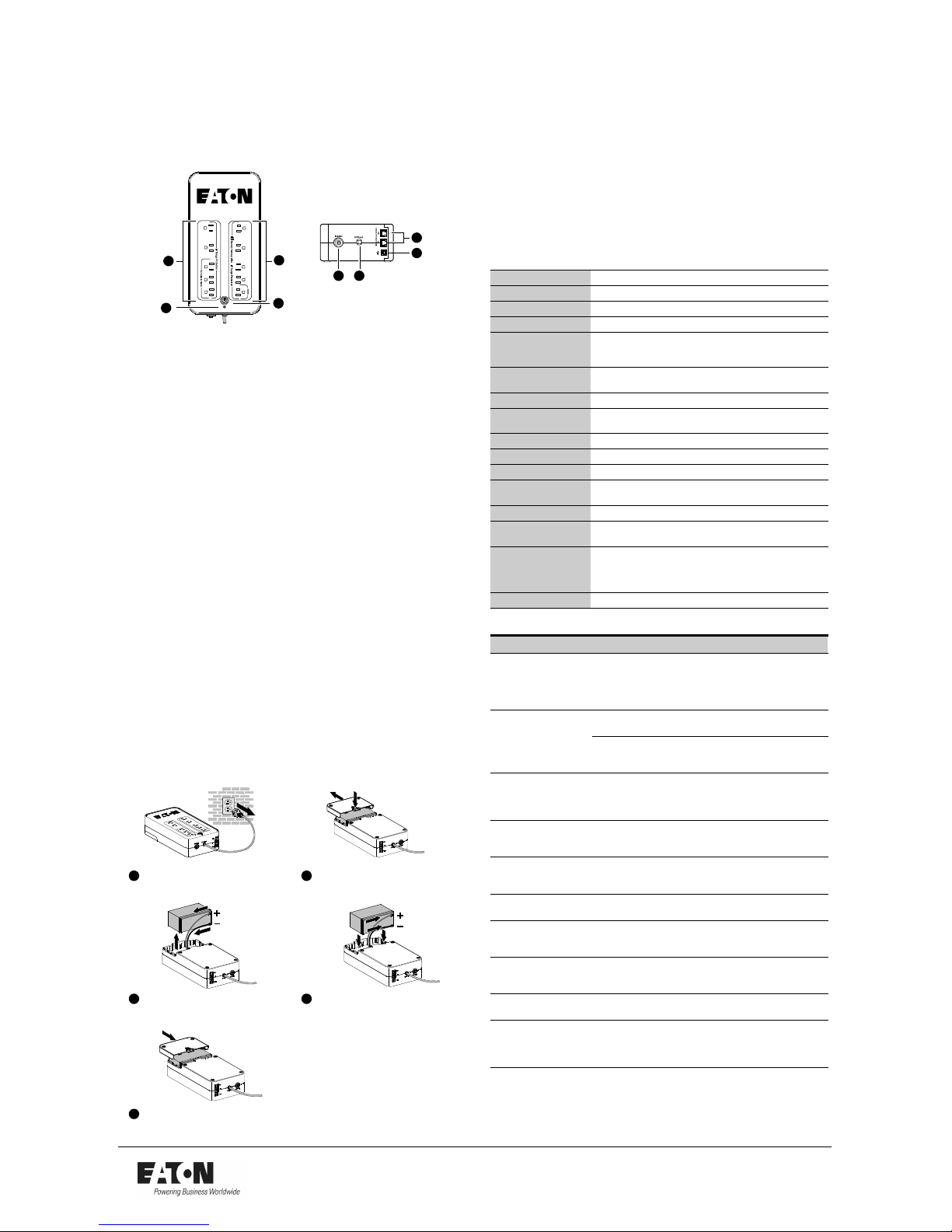
Indicators
1
2
3
4
6
5
7 8
1. On/Off Button
Button that controls power to the UPS and initiates the self-test function.
S Press the On/Off button to turn on the UPS.
S Press the On/Off button again to turn off the UPS.
The UPS performs a self-test for about 5 seconds when the UPS is turned on.
2. Fault/Warning (Red) LED
Indicates that a fault or warning condition is present.
S A flashing red LED indicates that a Site Wiring Fault exists.
S A solid illuminating red LED indicates that an internal UPS fault exists, or that
the battery should be replaced.
3. Surge Protection Outle ts
Output receptacles that provide surge and spike protection only.
S 350–550 VA models have four 5-15R surge protection outlets.
S 750 VA model has five 5-15R surge protection outlets.
4. Battery Backup and Surge Protection Outlets
Output receptacles that provide both backup and surge protection.
S 350–550 VA models have four 5-15R backup and surge protection outlets.
S 750 VA model has five 5-15R backup and surge protection outlets.
5. Modem/Phone/DSL/Fax Surge Protection Ports
A modem or Ethernet data line can be protected against surges by connecting
it through the UPS. Connect the device cable between the wall outlet and the
UPS, and use a similar cable between the UPS and the device.
6. USB Communication Port (450 VA, 550 VA, and 750 VA models only)
The built-in USB port connects to your computer (with the provided USB cable).
The Personal Solution-Pac monitoring and shutdown software can be
configured to automatically save your files and shut down your computer in the
event of a prolonged power outage. Your computer can receive the status of
utility power line, utility power failure, on battery, and low battery by contact
closure signals that are sent through the USB port.
7. Circuit Breaker (resettable)
The circuit breaker button protrudes when the overload condition occurs. If the
button protrudes, disconnect some of the non-essential equipment and reset
the circuit breaker by pressing the button in.
8. Input Power Cord
Six-foot line cord.
Replace Battery
Turn the UPS over and press in the
release tab. Slide the battery cover
off the UPS.
Connect the battery wires firmly to the
replacement battery terminals; red to
positive (+), black to negative (–). Insert the
replacement battery into the battery
compartment.
3
Slide the battery cover on the UPS until
the release tab locks into place.
2
Pull out the battery and disconnect
the battery wires.
4
1
Turn off the UPS and disconnect the
UPS from the power source.
5
Service and Support
For questions and/or problems, please call your local distributor or the Eaton
Customer Support Center at one of the following telephone numbers and ask for a
UPS technical representative.
United States: 1.800.356.5737
Europe, Middle East, and Africa: +44.17.53.608.700
Asia: +852.2830.3030
Australia: +61.3.9706.5022
Please have the following information ready when you call the Eaton Customer
Support Center: Model number, serial number, symptoms of failure or problem,
customer return address, and contact information. If repair is required, you will be
given a Returned Material Authorization (RMA) Number. This number must appear
on the outside of the package and on the Bill of Lading (if applicable). Use the
original packaging or request packaging from the Eaton Customer Support Center
or distributor. Units damaged in shipment as a result of improper packaging are not
covered under warranty. A replacement unit will be shipped, freight prepaid for all
units under warranty. For additional information please visit us online at
www.eaton.com/powerquality.
Specifications
Model 3S350 3S450 3S550 3S750
UPS Power 350 VA / 200W 450 VA / 270W 550 VA / 330W 750 VA / 450W
Input Voltage Range 96V–138V, adjustable to 75V–144V through Personal Sol ution-Pac
Input Frequency 50/60 Hz (46–7 0Hz working range)
Voltage/Frequency of
Battery Backup Outlets in
Battery Mode
115V +15% -20% / 50–60Hz ± 1%
Input Protecti on 10A resettable
circuit br eaker
12A res ettable circuit breaker
Transfer Ti me 5mstypical
Phone / ISDN / ADSL /
Ethernet Surge Protection
RJ-45
Sealed Lead Acid Batt ery 12V, 4.5Ah 12V, 4.5Ah 12V, 5Ah 12V, 9Ah
Operating Temperatur e 0°Cto40°C(32°Fto 104°F)
Storage Temperatur e -2.5°Cto+55°C(28°F to 131°F)
Operating Relati ve
Humidity
0 to 85% noncondensing
Safety Standar ds UL 1778
Electromagnetic
Compatibility Standards
FCC Part 15 Class B
UPS Dimensions
(H
×W×D)
335 × 140 × 86 mm
(13.2”
× 5.5” × 3.4”)
335 × 170 ×
86 mm
(13.2”
× 6.7”
× 3.4”)
UPS Weight 2.9 Kg (6.4 lb) 4.2 Kg (9.3 lb)
Troubleshooting
Problem Diagnostic Solution
The Fault/War ning LED
flashes r ed immediately
after plugging the UPS into
a wall outlet.
A Site Wiring Fault has
occurred. The outlet that the
UPS is plugged int o is not
properly gr ounded or
properly wi red.
Have a qualified electrician
correct the wiring.
The outlets are not
powered.
The wall outlet is not
powered.
Supply power to the wall outlet.
The circuit breaker has been
tripped by an overload on the
UPS output.
Reduce the amount of equipment
plugged into the UPS and press
the circuit breaker in to reset.
The On/Off button flashes
green and the audio alarm
beeps.
The UPS frequently operates
on battery power because
the AC power sour ce is of
poor quality .
Have the electrical installation
checked by a prof essional or use
another wall outlet.
The On/Off button flashes
green and the audio alarm
beeps continuousl y.
The UPS battery backup
outlets ar e overloaded.
Disconnect exces s equipment
connected to the batt ery backup
outlets.
AC power is av ailable, but
the UPS operates on
battery power .
The UPS circuit br eaker
tripped due to an overload
on the UPS output.
Reduce the amount of equipment
plugged into the UPS and press
the circuit breaker in to reset.
Battery back up outlets are
not powered.
The On/Off button is not
illuminated.
Press the On/Off button and verify
that it illuminates green.
The connected devices are
not powered when AC
power fails.
The devices are connected
to the Surge Pr otection only
outlets.
Connect the devi ces to the Bat tery
Backup outlets .
The telephone line i s
disturbed or modem
access is not possible.
Surgeprotectiononthe
telephone line is no longer
provided.
Disconnect the telephone line
from the wall outlet and contact
your serv ice representativ e.
The Fault/War ning LED
illuminates red.
The battery has reached the
end of its service l ife.
Replace battery .
The Fault/War ning LED
illuminates red and the
audio alarm beeps every
30 seconds .
A fault has occurred on the
UPS. The battery backup
outlets ar e not powered.
Contact your service
representative.
 Loading...