

Eaton 350 Series Technical Instructions
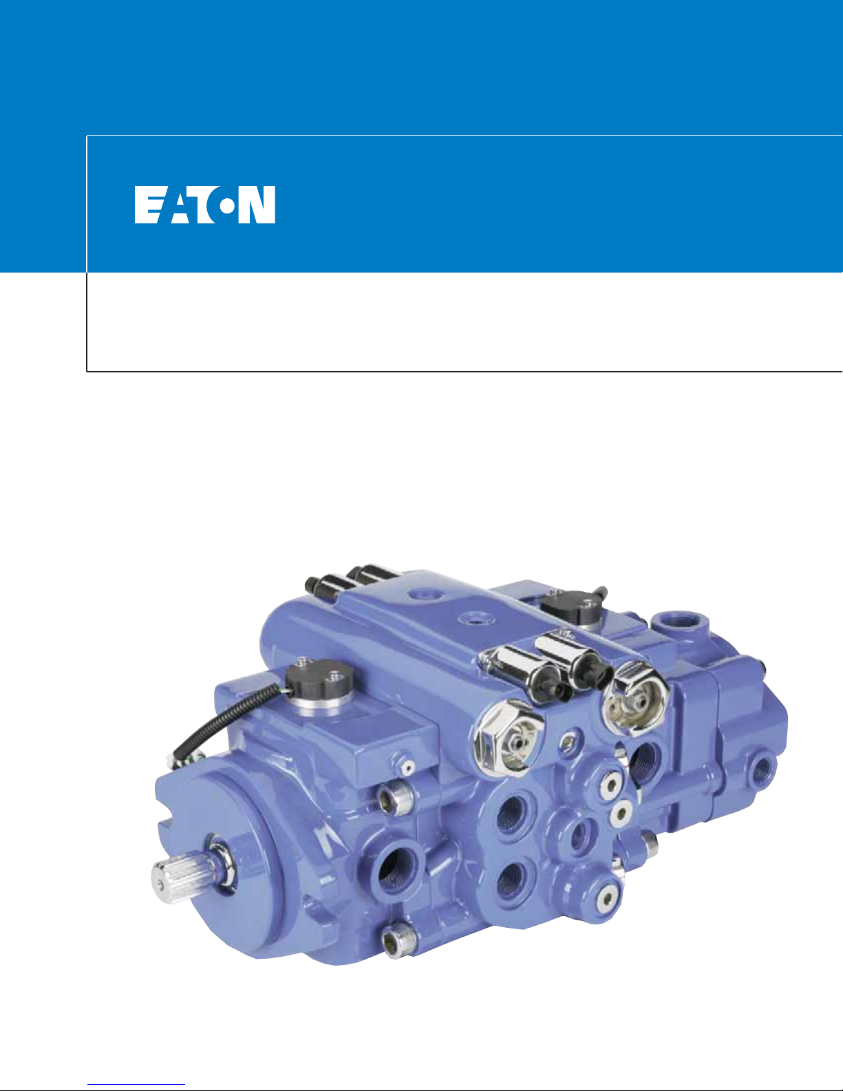
Dual Path Mobile Pump
Technical Manual
350 Series
350 Series Mobile Pump
Introduction ........................................................................................................................................................................................2
Features, Controls, Applications and Specifications ..........................................................................................................................3
Model Code......................................................................................................................................................................................4-5
Dimensional Drawings
Manual Servo Displacement Control ..........................................................................................................................................6-7
Solenoid Displacement Control..................................................................................................................................................8-9
Hydraulic Remote Control............................................................................................................................................................10
Magnetic Speed Sensor ..............................................................................................................................................................11
2 EATON Dual Path Mobile Pump E-PUPI-TM005-E July 2006
The 350 Series mobile pump
is an advanced, closed circuit,
servo controlled, axial piston
design offered as either a single or dual pump (two pumps
in one housing) for medium
duty hydrostatic circuits.
These pumps can be combined with an Eaton motor to
transfer and control hydraulic
power in many different ways.
An efficient, reliable and
durable rotating piston group
allows the 350 series pump to
maintain continuous pressures to 280 bar (4000 psi)
and 380 bar (5500 psi) rated
levels. This pressure capability, coupled with high allowable input speed (3600 RPM),
along with a compact package
means superior power density
in the market place.
*Not yet released
High load, taper roller bearings and a stiff drive shaft help
provide long bearing life at
rated mobile conditions,
reducing operating costs and
extending operating life.
350 Series pumps feature a
needle bearing under the
swash plate. This feature provides for better temperature
and contamination resistance.
The swash plate bearing
offers low control hysteresis
when matched with Eaton
control technologies.
The 350 series pump offers
the latest design in Eaton technologies for closed circuit piston pumps along with a wide
variety of responsive controls.
These controls include
mechanically or electricallyactuated feedback controls,
hydraulic or electronic proportional controls and a three
position (Forward-NeutralReverse) electric control.
A large input shaft diameter
allows more through put power,
even with an integral charge
pump. When the 350 series
pump is fully loaded as much as
56 kW (75 hp) of through put
power is av ailable for auxiliary
hydraulic pow er needs from the
SAE B auxiliary mounting pad.
350 Series pumps operate at
a level of quietness that
exceeds the requirements of
today's demanding work conditions. Another pump feature
- a serviceable, bimetal valve
plate - improves pump filling
characteristics which, in turn,
reduces fluid-borne noise and
extends pump life. A highly
engineered pump housing and
swash plate also minimizes
noise and vibration.
Mounting flanges are offered
in SAE B and C configurations
and ports are offered in SAE,
ISO tube and flange and STC
direct port versions. Opposite
or same side port versions are
available to facilitate plumbing
and help the pump fit your
machine space needs. An integral gerotor charge pump can
be provided with up to four different displacement sizes allo wing for either remote or inlet
charge filter options.
The 350 series pump offers a
full range of product features
and has the ability to match
the needs of many different
customer platforms. It supports increased power
requirements in Agricultural,
Construction and Utility markets and allows for a wide variety of installation opportunities
for global machine design.
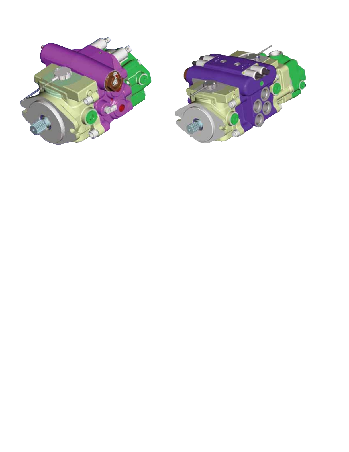
Single Assembly* Dual Path Assembly
Table of Contents
350 Series
Mobile Pump
Introduction
3
EATON Dual Path Mobile Pump E-PUPI-TM005-E2 September 2007
Features,
Controls,
Applications and
Specifications
Controls
• Mechanical servo and
Hydraulic (non-feedback)
• Electro-proportional “EP”
• Proportional valve control
with electronic swash
plate feedback
- Non-contacting sensor
- Fast response, precise,
real-time pump control
- Best electro-hydraulic con-
trol for mobile hydrostatic
transmissions available on
the market today*
* Interface requires proprietary
Eaton electronic control or
control algorithms
Features
• Symmetrical 4-Bolt design
• Polyacrylate Shaft Seal
• 15-Tooth splines, 14-Tooth
splines, Taper Input Shafts
• Case Drains location
(one connection needed)
• Shaft mounted on Tapered
roller bearings
• Optional Speed Pickup
Location
• Swash plate bearings
• Same Side or Opposite
Side Main Work Ports
Typical Applications
• Pavers, Rollers
• T elescopic Booms
• Boring Machines
• T renc hing Machines
• Sweepers
• Small Sprayers
• T elehandlers
• Stump Grinders
• Compact Wheel Loaders
• Rough Terrain Fork Lifts
• Material Handling
Equipment
• Skid Steer Loaders
• Windrowers/Sprayers
UNITS 41 49 62
Displacement cc/rev (cid) 41 (2.50) 49 (3.00) 62 (3.80)
Input Speed Min RPM 500 500 500
Max RPM 3600 3600 3600
Continuous Pressure Bar (psi) 280 (4000) 280 (4000) 280 (4000)
Rated Pressure Bar (psi) 380 (5500) 380 (5500) 380 (5500)
Charge Pressure Bar (psi) 15-31 (220-450) 15-31 (220-450) 15-31 (220-450)
Flow at Rated Speed LPM (GPM) 139 (37) 166 (44) 210 (56)
Mounting 2-Bolt SAE B 2-Bolt SAE B
4-Bolt SAE C 4-Bolt SAE C 2-Bolt SAE C
2-Bolt SAE C 2-Bolt SAE C 4-Bolt SAE C
Specifications:
Continuous Pressure:
280 Bar (4000 psi)
Rated Pressure:
380 Bar (5500 psi)
Displacements:
41cc (2.50 cid), 49 cc (3.00
cid), 62 cc (3.8 cid).
Estimated weight for a 350 series pump
with opposite side main ports with charge
pump - 81.8 Kg (181 lbs).
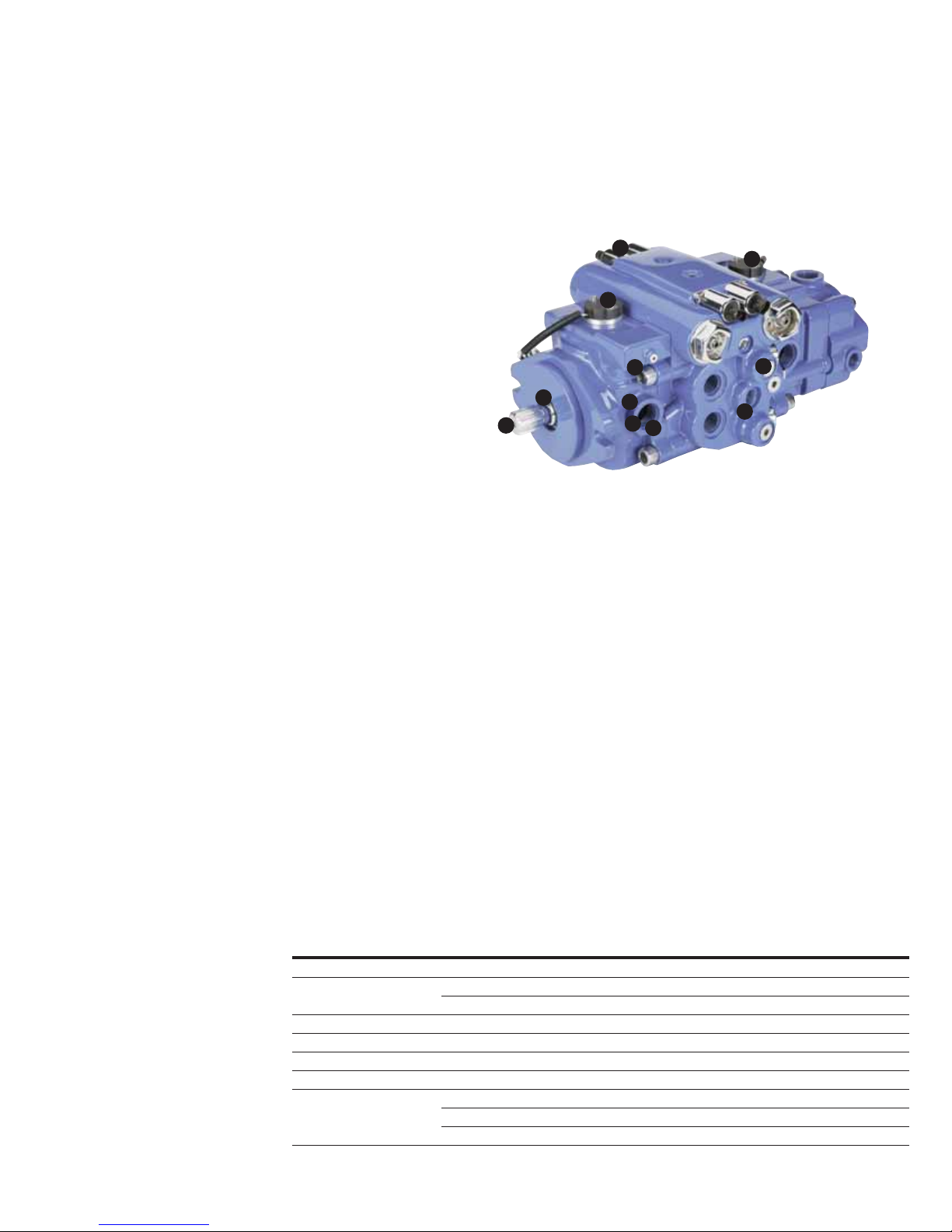
2. Symmetrical
4 Bolt Design
9. Swash Plate
Position Sensors
1. Solenoid
Displacement
Control
3. Polyacrylate
Shaft Seal
4. 15-Tooth Splines
14-Tooth Splines
Taper Input Shafts
Shaft Mounted on
Tapered Roller Bearings
5. Case Drains Location
(one connection needed)
7. Same Side or Opposite
Side Main Work Ports
8. Swash Plate
Bearings
6. Optional Speed
Pickup Location
9
1
9
2
3
4
8
5
6
7
5
Feature Locations
4 EATON Dual Path Mobile Pump E-PUPI-TM005-E2 September 2007
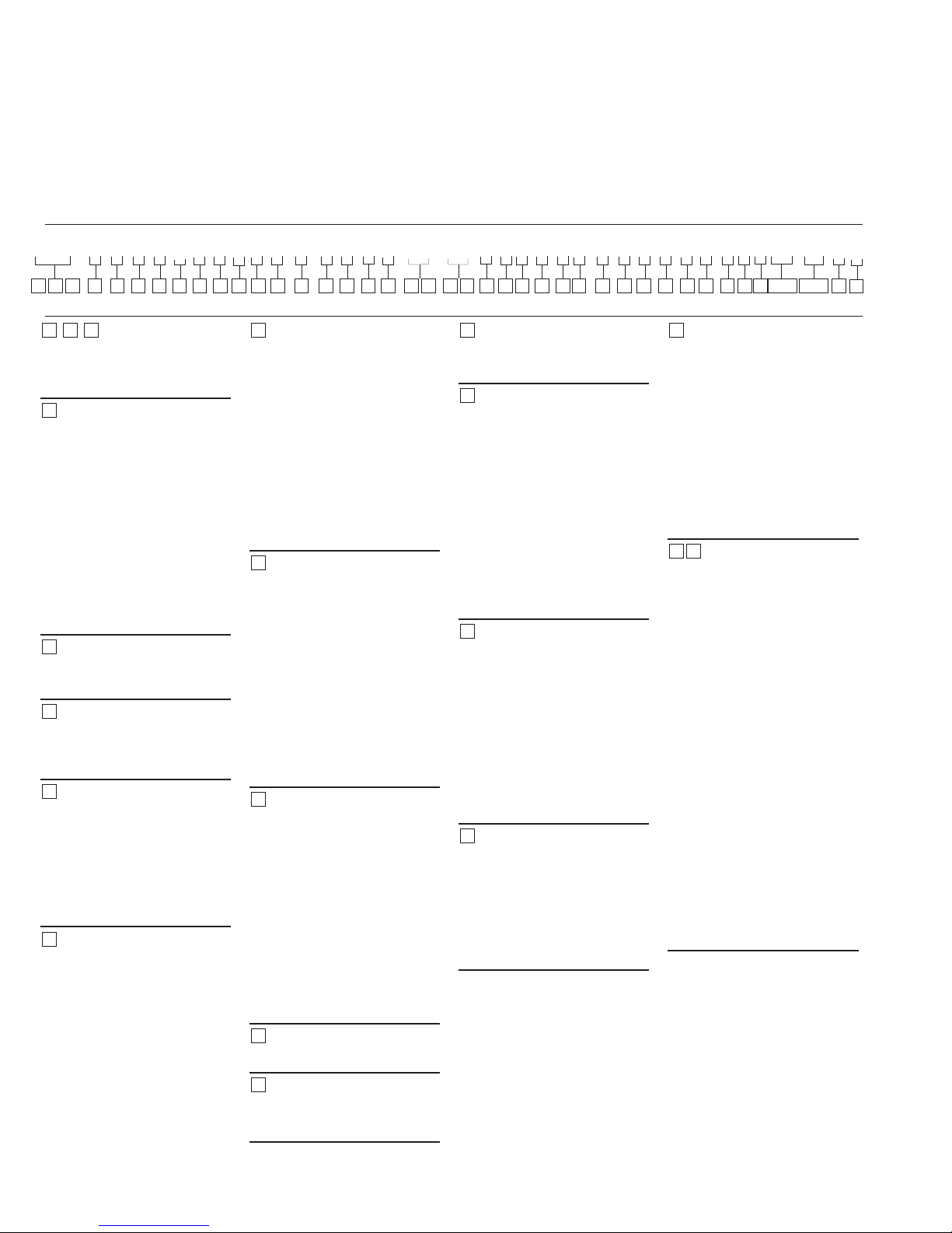
Model Code
Code Title
AED – Dual Servo Controlled
Variable Displacement Axial
Piston Pump
Displacement & Rotating
Kit- Front
1 – 41.0 cm3/r [2.50 in3/r]
2 – 49.2 cm
3
/r [3.00 in3/r]
3 – 62.3 cm
3
/r [3.80 in3/r]
4 – 35.0 cm
3
/r [2.10in3/r]
Destroked from -
41.0 cm
3
/r [2.50 in3/r]
5 – 45.0 cm
3
/r [2.75 in3/r]
Destroked FROM -
49.2 cm
3
/r [3.00 in3/r]
6 – 54.0 cm
3
/r [3.30 in3/r]
Destroked FROM -
62.3 cm
3
/r [3.80 in3/r]
Input Shaft Rotation
L – Left hand rotation (CCW)
R – Right hand rotation (CW)
Front Mounting
A – 2 Bolt C (SAE J744-127-2)
B – 4 Bolt C (SAE J744-127-4)
C – 2 Bol t B (S AE J744-101-2 )
Input Shaft
A – Taper shaft 1.0 dia 1.5 taper
B – 14 Tooth 12/24 Pitch Spline
Shaft
C –15 Tooth 16/32 Pitch Spline
Shaft
D –19 Tooth 16/32 Pitch Spline
Shaft
Valve Plate - Front
A – Type 1- Standard
Relief Setting for Front
Main Port A - Front
0 – None, no relief valve or
check valve
A – Check valve only
J – 207 bar [3000 lbf/in
2
]
K – 224 bar [3250 lbf/in
2
]
L – 241 bar [3500 lbf/in
2
]
M – 259 bar [3750 lbf/in
2
]
N – 280 bar [4000 lbf/in
2
]
R – 310 bar [4500 lbf/in
2
]
T – 345 bar [5000 lbf/in
2
]
U – 362 bar [5250 lbf/in
2
]
V – 380 bar [5500 lbf/in
2
]
Relief Setting for Front
Main Port B - Front
0 – None, no relief valve or
check valve
A – Check valve only
J – 207 bar [3000 lbf/in
2
]
K – 224 bar [3250 lbf/in
2
]
L – 241 bar [3500 lbf/in
2
]
M – 259 bar [3750 lbf/in
2
]
N – 280 bar [4000 lbf/in
2
]
R – 310 bar [4500 lbf/in
2
]
T – 345 bar [5000 lbf/in
2
]
U – 362 bar [5250 lbf/in
2
]
V – 380 bar [5500 lbf/in
2
]
Displacement & Rotating
Kit - Rear
1 – 41.0 cm3/r [2.50 in3/r]
2 – 49.2 cm
3
/r [3.00 in3/r]
3 – 62.3 cm
3
/r [3.80 in3/r]
4 – 35.0 cm
3
/r [2.10in3/r]
Destroked from -
41.0 cm
3
/r [2.50 in3/r]
5 – 45.0 cm
3
/r [2.75 in3/r]
Destroked FROM -
49.2 cm
3
/r [3.00 in3/r]
6 – 54.0 cm
3
/r [3.30 in3/r]
Destroked FROM -
62.3 cm
3
/r [3.80 in3/r]
Valve Plate - Rear
A – Type 1- Standard
Relief Setting For Front
Main Port A - Rear
Ref Position 9 for options
Relief Setting For Front
Main Port B - Rear
Ref Position 10 for options
Charge Pump
0 – No Charge Pump
1 – 13.9 cm
3
/r [.85in3/r],
1.3125-12 UN-2B SAE O-Ring
Suction Inlet Port (S)
2 – 17.4 cm
3
/r [1.06 in3/r],
1.3125-12 UN-2B SAE O-Ring
Suction Inlet Port (S)
3 – 21.0 cm
3
/r [1.28 in3/r],
1.3125-12 UN-2B SAE O-Ring
Suction Inlet Port (S)
4 – 23.1 cm
3
/r [1.41 in3/r],
1.3125-12 UN-2B SAE O-Ring
Port for Suction Inlet (S)
Charge Relief Setting
0 – No Charge Relief Setting
1 – 17.2 - 20.7 bar [250-300 lbf/in
2
]
Relieved to Case
2 – 20.7 - 24.1 bar [300-350 lbf/in
2
]
Relieved to Case
3 – 24.1 - 27.6 bar [350-400 lbf/in
2
]
Relieved to Case
4 – 27.6 - 31 bar [400-450 lbf/in
2
]
Relieved to Case
5 – 13.8 - 1 7.2 bar [400-450 lbf/in
2
]
Relieved to Case
Charge Port Location
0 – None
1 – Inlet Right Side C2 (Only
with Main Ports opposite side)
2 – Inlet Left Side C1
3 – Inlet Bottom C3 (Only with
Main Ports Same Side, No
Bypass Valv e)
Auxiliary (Rear) Mount &
Output Shaft
A – 2 Bol t B (S AE J744-101-2 )
Accepts 13T, 16/32 Pitch
Spline
B – 2 Bolt B (SAE J744-101-2)
Accepts 15T, 16/32 Pitch
Spline
C – 2 Bolt A (SAE J744- 82-2)
Accepts 11T, 16/32 Pitch
Spline
D – 2 Bolt A (SAE J744-82-2)
Accepts 9T, 16/32 Pitch Spline
Control Assembly -
Front
SA – Solenoid Control -
12 Volt With Non-Contact
Feedback Sensor with MetriPak Electrical Connectors
SB – Solenoid Control 12 Volt
SC – Solenoid Control 12 Volt
HA – Hydraulic Remote - Non
Feedback, 5-15 bar [72-217
lbf/in2] Pilot Pressure
MA – Manual Control,Wide
Band Neutral
MB – Manual Control,
Standard
MC – Manual Control, High Gain
MD – Manual Control,
Wide Band Neutral, Neutral
Lockout switch
ME – Manual Control, Standard,
Neutral Lockout switch
MF – Manual Control, High
Gain, Neutral Lockout switch
19 20
14 18
16
17
15
13
12
932
4
11
10
8
7
6
5
1
AED * * * * A * * * * * * * * * * ** ** * * * 0 * * * * * * * * * * * ** ** A A
1 2 3 4 5 6 7 8 9 10 11 12 13 14 15 16 17 18 19 20 21 22 23 24 25 26 27 28 29 30 31 32 33 34 35
38,39 40,41 42
43
36 37
 Loading...