

Eaton 1 Series, 3333, 3331, 3931, 3933 Parts And Service
...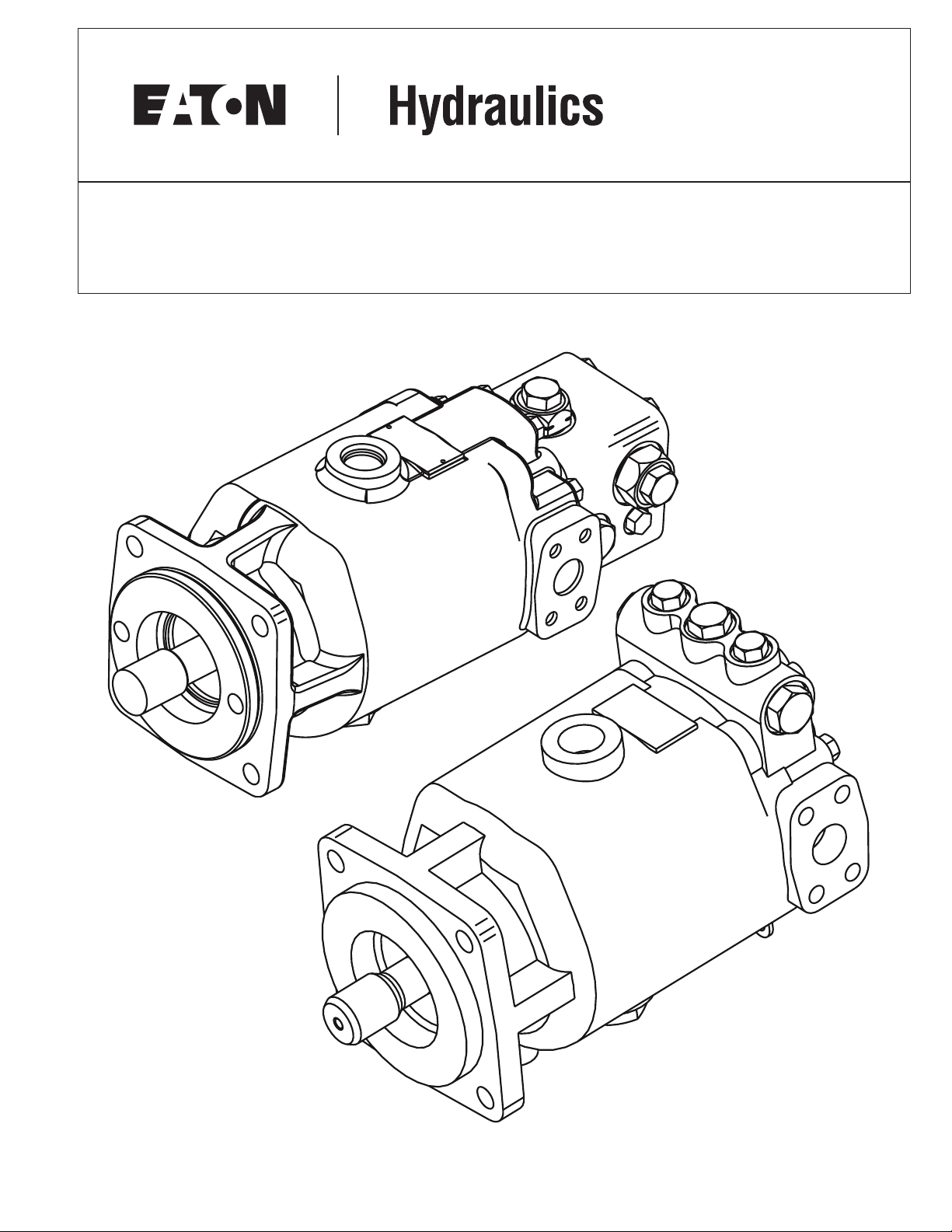
Series 1 Heavy Duty Hydrostatic Fixed
Displacement Motors
Parts and Service
Model 3331/3333
Model 3931/3933
Model 4631/4631
Model 5431/5433
Model 6431/6433

2 EATON Series 1 Heavy Duty Hydrostatic Fixed Displacement Motors Parts and Repair E-MOPI-TS002-E September 2004
Introduction . . . . . . . . . . . . . . . . . . . . . . . . . . . . . . . . . . . . . . . . . . . . . . . . . . . . . . . . . . . . . . . . . . . . . . . . . . . . . . . . . . . . . . . . . . . . . . . . . . . . . . . . . . . . . . . . . . 3
Identification Tag System . . . . . . . . . . . . . . . . . . . . . . . . . . . . . . . . . . . . . . . . . . . . . . . . . . . . . . . . . . . . . . . . . . . . . . . . . . . . . . . . . . . . . . . . . . . . . . . . . . . . . . . 3
Tools Required . . . . . . . . . . . . . . . . . . . . . . . . . . . . . . . . . . . . . . . . . . . . . . . . . . . . . . . . . . . . . . . . . . . . . . . . . . . . . . . . . . . . . . . . . . . . . . . . . . . . . . . . . . . . . . . . . .3
Parts Drawing . . . . . . . . . . . . . . . . . . . . . . . . . . . . . . . . . . . . . . . . . . . . . . . . . . . . . . . . . . . . . . . . . . . . . . . . . . . . . . . . . . . . . . . . . . . . . . . . . . . . . . . . . . . . . . . . . .4
Parts Lists . . . . . . . . . . . . . . . . . . . . . . . . . . . . . . . . . . . . . . . . . . . . . . . . . . . . . . . . . . . . . . . . . . . . . . . . . . . . . . . . . . . . . . . . . . . . . . . . . . . . . . . . . . . . . . . . . 5-10
Drive Shaft . . . . . . . . . . . . . . . . . . . . . . . . . . . . . . . . . . . . . . . . . . . . . . . . . . . . . . . . . . . . . . . . . . . . . . . . . . . . . . . . . . . . . . . . . . . . . . . . . . . . . . . . . . . . .6-8
End Cover . . . . . . . . . . . . . . . . . . . . . . . . . . . . . . . . . . . . . . . . . . . . . . . . . . . . . . . . . . . . . . . . . . . . . . . . . . . . . . . . . . . . . . . . . . . . . . . . . . . . . . . . . . . . . . .9
Valve Block . . . . . . . . . . . . . . . . . . . . . . . . . . . . . . . . . . . . . . . . . . . . . . . . . . . . . . . . . . . . . . . . . . . . . . . . . . . . . . . . . . . . . . . . . . . . . . . . . . . . . . . . . . . . .10
Valve Block Kits . . . . . . . . . . . . . . . . . . . . . . . . . . . . . . . . . . . . . . . . . . . . . . . . . . . . . . . . . . . . . . . . . . . . . . . . . . . . . . . . . . . . . . . . . . . . . . . . . . . . . . . . .11
Rotating Group . . . . . . . . . . . . . . . . . . . . . . . . . . . . . . . . . . . . . . . . . . . . . . . . . . . . . . . . . . . . . . . . . . . . . . . . . . . . . . . . . . . . . . . . . . . . . . . . . . . . . . . . . .12
Motor Housing . . . . . . . . . . . . . . . . . . . . . . . . . . . . . . . . . . . . . . . . . . . . . . . . . . . . . . . . . . . . . . . . . . . . . . . . . . . . . . . . . . . . . . . . . . . . . . . . . . . . . . . . . .13
Kits . . . . . . . . . . . . . . . . . . . . . . . . . . . . . . . . . . . . . . . . . . . . . . . . . . . . . . . . . . . . . . . . . . . . . . . . . . . . . . . . . . . . . . . . . . . . . . . . . . . . . . . . . . . . . . . . . . .14
Dis-assembly Shaft Seal . . . . . . . . . . . . . . . . . . . . . . . . . . . . . . . . . . . . . . . . . . . . . . . . . . . . . . . . . . . . . . . . . . . . . . . . . . . . . . . . . . . . . . . . . . . . . . . . . . . . . . . .15
Dis-assembly/Assembly Valve Block . . . . . . . . . . . . . . . . . . . . . . . . . . . . . . . . . . . . . . . . . . . . . . . . . . . . . . . . . . . . . . . . . . . . . . . . . . . . . . . . . . . . . . . . . . . . . . .16
Dis-assembly End Cover . . . . . . . . . . . . . . . . . . . . . . . . . . . . . . . . . . . . . . . . . . . . . . . . . . . . . . . . . . . . . . . . . . . . . . . . . . . . . . . . . . . . . . . . . . . . . . . . . . . . . . . .18
Dis-assembly Rotating Group . . . . . . . . . . . . . . . . . . . . . . . . . . . . . . . . . . . . . . . . . . . . . . . . . . . . . . . . . . . . . . . . . . . . . . . . . . . . . . . . . . . . . . . . . . . . . . . . . . . .19
Assembly Rotating Group . . . . . . . . . . . . . . . . . . . . . . . . . . . . . . . . . . . . . . . . . . . . . . . . . . . . . . . . . . . . . . . . . . . . . . . . . . . . . . . . . . . . . . . . . . . . . . . . . . . . . . .20
Assembly End Cover . . . . . . . . . . . . . . . . . . . . . . . . . . . . . . . . . . . . . . . . . . . . . . . . . . . . . . . . . . . . . . . . . . . . . . . . . . . . . . . . . . . . . . . . . . . . . . . . . . . . . . . . . . .23
Assembly Shaft Seal . . . . . . . . . . . . . . . . . . . . . . . . . . . . . . . . . . . . . . . . . . . . . . . . . . . . . . . . . . . . . . . . . . . . . . . . . . . . . . . . . . . . . . . . . . . . . . . . . . . . . . . . . . .24
Assembly Valve Block/Integral Valves . . . . . . . . . . . . . . . . . . . . . . . . . . . . . . . . . . . . . . . . . . . . . . . . . . . . . . . . . . . . . . . . . . . . . . . . . . . . . . . . . . . . . . . . . . . . .27
Special Tools . . . . . . . . . . . . . . . . . . . . . . . . . . . . . . . . . . . . . . . . . . . . . . . . . . . . . . . . . . . . . . . . . . . . . . . . . . . . . . . . . . . . . . . . . . . . . . . . . . . . . . . . . . . . . . .28-29
Hydraulic Fluid Recommendations . . . . . . . . . . . . . . . . . . . . . . . . . . . . . . . . . . . . . . . . . . . . . . . . . . . . . . . . . . . . . . . . . . . . . . . . . . . . . . . . . . . . . . . . . . . . . .30-31
Series 1
Hydrostatic
Fixed Motor
Table of Contents

3EATON Series 1 heavy Duty Hydrostatic Fixed Displacement Motors Repair E-MOPI-TS002-E September 2004
ID Tag
A - Displacement (cu.in./rev.)
0033 = 3.3
0039 = 3.9
0046 = 4.6
0054 = 5.4
0064 = 6.4
B
- Identifies Type of Product
31 = Fixed Displacement Motor with Face Seal
33 = Fixed Displacement Motor with Lip Seal
C - Identifies Specific Unit Configuration
D - Month of Manufacture
E - Year of Manufacture
F - Specific Serial Number of Unit
•Stationary Seal Puller (1/4
in. x 20 UNC capscrew,
3 to 4 in. long)
• Retaining Ring Pliers,
No. 5 or 7
•Breaker Bar or Ratchet
Wrench
• 1-3/8 in. Hex Wrench
•1 in. Hex Wrench
• 9/16 in. Socket
• 5/8 in. Socket
•Torque Wrench
(200 lb-ft capacity)
• 1/4 in. Hex Bit Socket
• 1/4 in. Hex Key
• Loctite® No. 271
• Pliers
• Punch
• Magnetic Base Indicator
• Hammer
• Bearing Press or Driver
•Light Petroleum Jelly
• Cleaning Solvent
• Micrometer or Vernier
Calipers
• Small Screwdriver
(1/8 in. blade)
• Clean Lint Free Rags
Special Tools needed
(shown on pages 26 and 27).
• Bearing Cone Driver
• Rotating Seal Puller
• Limit Stop for Bearing
Cone Installation
• Headless 5/16 in. Cap
Screws, 5 to 6 in. Long (2)
• Low Clearance Bearing
Puller
Tools Required
This manual will provide you with service information and procedures for disassembly and reassembly of Eaton®Series 1 Heavy Duty Hydrostatic Fixed
Displacement Motors – Models 33, 39, 46, 54, and 64. Procedures outlined in this manual will allow you to better service your motors and obtain the best
results possible. To ensure accuracy of repair and prevent part loss or damage, certain components or subassemblies are disassembled, inspected, and
reassembled when removed from the motor.
Note: All requests or inquiries must be accompanied by the complete model and serial number.
Introduction
Eaton
Model No.
Serial No.
Rotation
Eaton Corporation
Hydraulics Division
Spencer, Iowa 51301
ABC
E
D
F
0000 00 - 000
00 00 000000
Important: Cleanliness is extremely important when repairing a hydrostatic pump or motor. Before disconnecting the lines, clean foreign material
from exterior of unit. Work in a clean area. Clean all metal parts in clean solvent. Blow parts dry with air. Don’t wipe parts with cloth or paper towel,
because lint or other matter could cause damage. Check all mating surfaces. Replace any parts that have scratches or burrs that could cause leakage.
Don’t use coarse grit paper, files or grinders on parts.
Note: All torque specifications are for lubricated threads. Bolts for gasketed surfaces should be checked for proper torque.
A good service policy is to replace all old seals with new seals whenever unit is disassembled. Lubricate seals (except metal sealing surfaces of shaft
seal assembly) with petroleum jelly. Use only clean, recommended oil when assembling unit. See Hydrostatic Fluid Recommendations on page 28-29 or
publication 03-401 and 03-405.
Refer to specific motor assembly
part listings for your Eaton motor
when ordering replacement parts.
Parts Lists are available from Eaton.
Sample tag shows motor
identification.
When ordering replacement parts,
you must include the
following information:
4
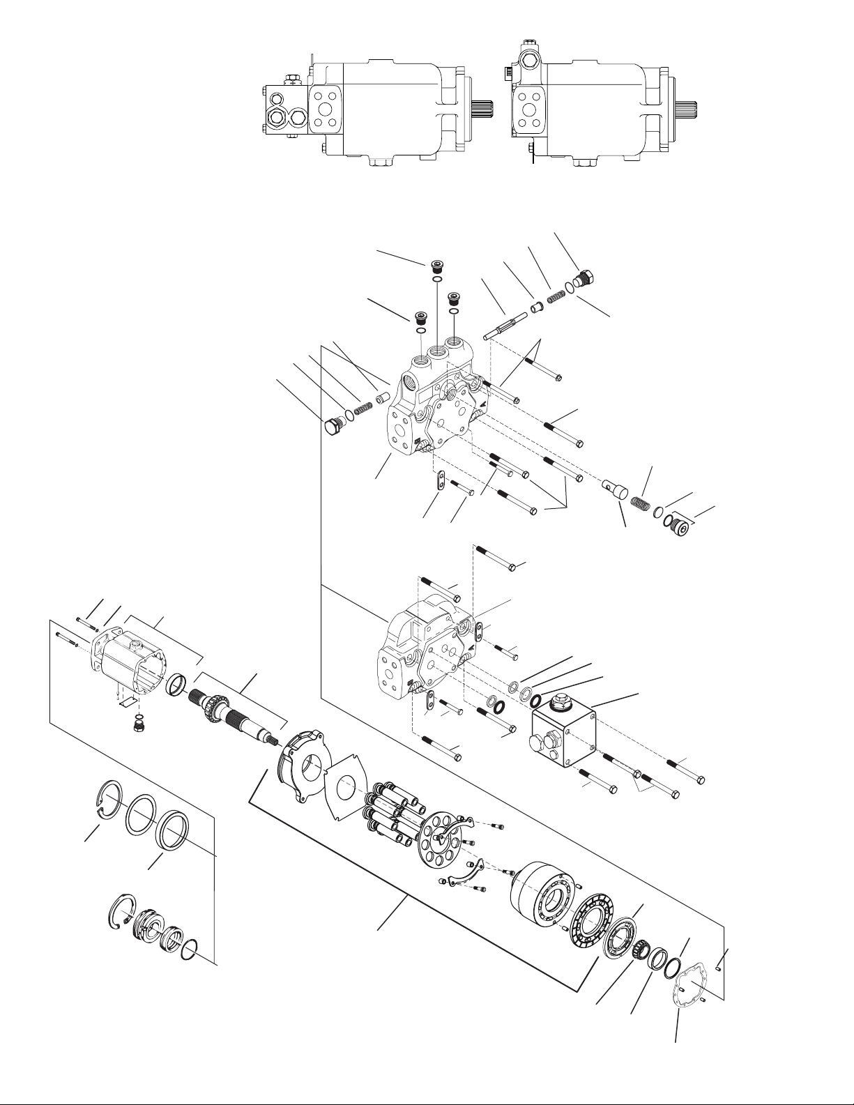
Parts
Assembly Drawing
23
21
or
19
15
17
18
16
14
13
990709-000
Lip Seal
Motors P/N XX33-XXX
(Current version)
990231-000
Face Seal
Motors P/N XX31-XXX
4
1
35
25
7
7
24
24
5
7
6
6
6
6
5
8
10
9
3
2
A
B
K
K
C
F
E
C
D
B
A
6
6
J
G
H
I
2
24
5
5
31
End Cover
with Integral
Shuttle and
Low Pressure
Relief Valve
or
End Cover
with Valve
Block
Motors with Valve Blocks
Motors with Integral Shuttle and Low
Pressure Relief Valves
EATON Series 1 Hydrostatic Fixed Motors Repair E-MOPI-TS002-E September 2004

5EATON Series 1 Heavy Duty Hydrostatic Fixed Displacement Motors Parts and Repair E-MOPI-TS002-E September 2004
ITEM REFERENCE
NO. PART NO. QTY. DESCRIPTION PAGES
1 See Table 2.0 1 Output Drive Shaft Subassembly for Motors with Lip Seal XX33-XXX (Current Production) 6
1 See Table 2.1 1 Output Drive Shaft Subassembly for Motors with Face Seal XX31-XXX 6-8
2 See Table 3.1 1 End Cover Subassembly for Motors with Integral Shuttle and Low Pressure Relief Valve 9
3 See Table 4.0, 4.1 1 End Cover for Motors with Valve Block Subassembly 10
3 See Table 4.2 1 Valve Block Subassembly 10
4 See Table 6.0 1 Fixed Motor Housing Subassembly 13
5 See Table 4.0 2 Hex Head Bolt 3/8-16 GR 8 9
6 See Table 4.0 4 Hex Head Bolt 3/8-16 GR 8 9
6 See Table 4.0 6 Hex Head Bolt 3/8-16 GR 8 9
7 See Table 4.0 4 Hex Head Bolt 3/8-16 GR 5 9
8 8775-021 1 Square Cut Seal Ring
9 8765-118 2 O-ring
10 101129-000 2 Back-up Ring
13 103224-000 1 End Cover Gasket (model 33/39/46)
13 103877-000 1 End Cover Gasket (model 54/64)
14 98202-000 3 Dowel Pin (5/16 x 5/8 long)
15 103230-000 1 33/39 Motor Valve Plate
15 104189-000 1 46 Motor Valve Plate
15 105104-000 1 54 Motor Valve Plate
15 105099-000 1 64 Motor Valve Plate
16 See Table 7.0 End Cover Bearing Shims 13
17 See Table 6.0 1 Bearing Cup* 13
18 See Table 6.0 1 Bearing Cone* 13
19 See Table 5.0-5.2 1 Rotating Group Subassembly 12
21 See Table 7.0 1 Seal Kit for Motors with Lip Seal only XX33-XXX (Current Production) 13
21 See Table 7.0 1 Seal Kit for Motors with Face Seal only XX31-XXX 13
23 See Table 7.0 1 Retaining Ring for Lip Seal 13
24 96558-000 2 Lifting Strap (models 33/39/46)
24 96559-000 2 Lifting Strap (models 54/64)
25 103223-000 2 Sealing Washer
31 104511-300 2 Cap Screw, Socket Hd 3/8-16
35 95912-300 2 Cap Screw, Socket Hd 5/16-18
*Cannot be purchased separately.
Parts
Table 1.0 Parts List
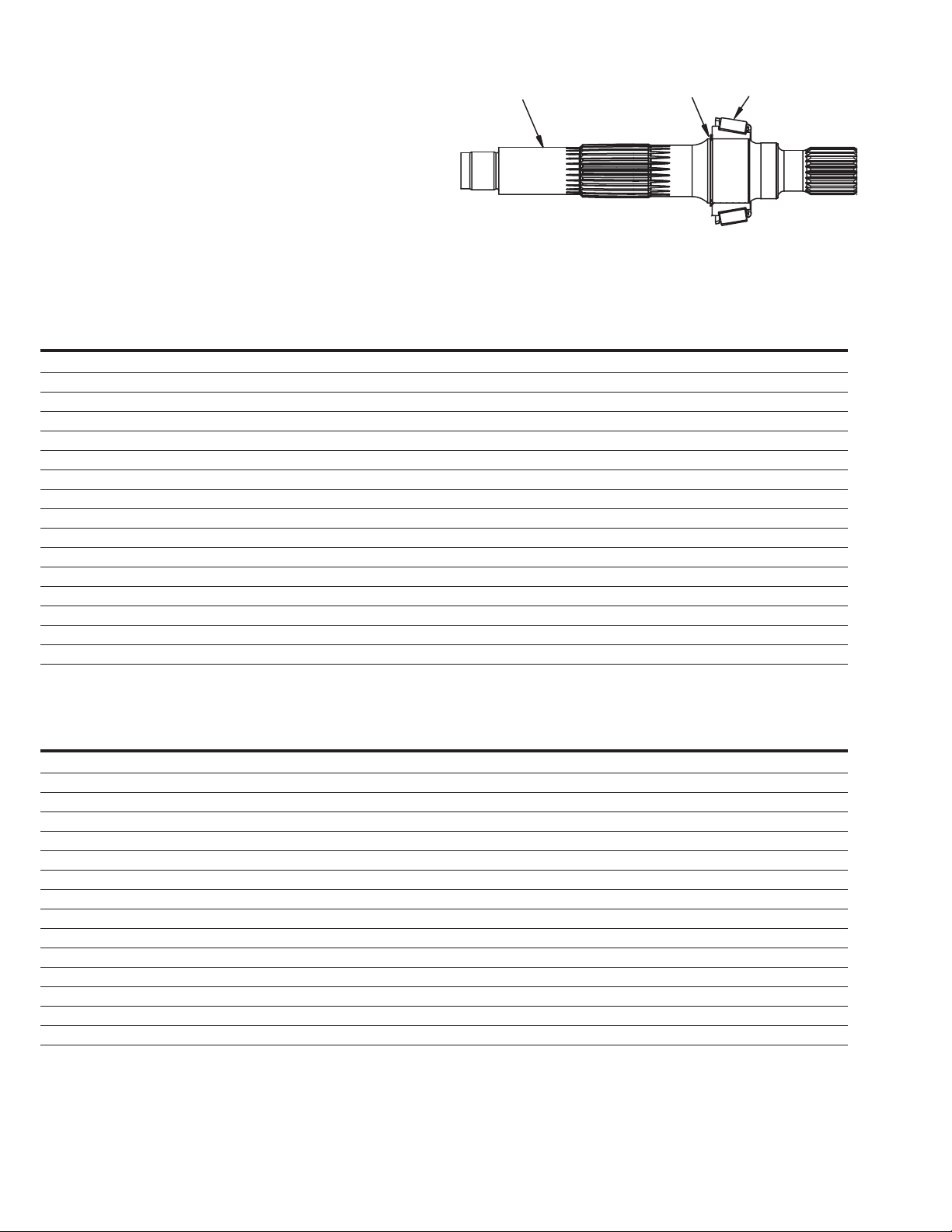
Table 2.0 Output Drive Shaft Assembly For Motors XX33-XXX (Lip Seal Design)
Models 3333-3933-4633
SHAFT
BEARING RETAINING
ASSEMBLY SHAFT CONE RING DESCRIPTION
112459-000 112458-000 103227-000 103222-188 23 Tooth, 16/32 Pitch Spline
112463-000 112462-000 103227-000 103222-188 20 Tooth, 16/32 Pitch Spline (3/8-24) UNF x [.75] DP
112465-000 112464-000 103227-000 103222-188 21 Tooth, 16/32 Pitch Spline
112467-000 112466-000 103227-000 103222-188 14 Tooth, 12/24 Pitch Spline
112480-000 112479-000 103227-000 103222-188 14 Tooth, 12/24 Pitch Spline, Speed Sensor
112482-000 112481-000 103227-000 103222-188 21 Tooth, 16/32 Pitch Spline, Speed Sensor
112498-000 112497-000 103227-000 103222-188 1.5 Diameter Straight with [.3750] X [2.5] Square key
112500-000 112499-000 103227-000 103222-188 19 Tooth, 16/32 Pitch Spline
112504-000 112503-000 103227-000 103222-188 1.375 Diameter Tapered W/ [.375] X [1.00] Square key
112506-000 112505-000 103227-000 103222-188 14 Tooth, 12/24 Pitch Spline (3/8-24) UNF x [.75] DP
112508-000 112507-000 103227-000 103222-188 23 Tooth, 16/32 Pitch SplinePitch Spline (3/8-24) UNF x [.75] DP
112510-000 112509-000 103227-000 103222-188 19 Tooth, 16/32, Pitch Spline, Speed Sensor
112519-000 112518-000 103227-000 103222-188 20 Tooth, 16/32, Pitch Spline, Speed Sensor
112521-000 112520-000 103227-000 103222-188 1.5 Diameter Straight W/ [.3750] X [2.5] Square key, (3/8-24) UNF x [.75] DP
112525-000 112524-000 103227-000 103222-188 1.5 Tapered with [.375] X [1.00] Square key
114289-000 114288-000 103227-000 103222-188 21 Tooth, 16/32 Pitch Spline (M10 x 1.5 threaded hole)
MODELS 5433-6433
SHAFT BEARING RETAINING
ASSEMBLY SHAFT CONE RING DESCRIPTION
112484-000 112483-000 103808-000 103222-200 14 Tooth, 12/24 Pitch Spline
113201-000 113201-000 103808-000 103222-200 23 Tooth, 16/32 Pitch Spline
113338-000 113337-000 103808-000 103222-200 21 Tooth, 16/32 Pitch Spline
113344-000 113343-000 103808-000 103222-200 23 Tooth, 16/32, Pitch Spline, Speed Sensor
113346-000 113345-000 103808-000 103222-200 23 Tooth, 16/32 Pitch Spline (3/8-24) UNF x [.75] DP
113348-000 113347-000 103808-000 103222-200 1.375 Diameter Tapered W/ [.375] X [1.00] Square Key
113350-000 113349-000 103808-000 103222-200 1.5 Diameter Straight W/ [.3750] X [2.5] Square Key
113352-000 113251-000 103808-000 103222-200 21 Tooth, 16/32, Pitch Spline, Speed Sensor
113356-000 113355-000 103808-000 103222-200 14 Tooth 12/24 Pitch Spline, Speed Sensor
113358-000 113357-000 103808-000 103222-200 1.5 Diameter Straight W/ [.3750] X [2.5] Square Key, (3/8-24) UNF x [.75] DP
113360-000 113359-000 103808-000 103222-200 21 Tooth, 16/32 Pitch Spline (3/8-24) UNF x [.75] DP
113362-000 113361-000 103808-000 103222-200 [1.500] Diameter Straight W/ [.3750] X [2.5] Square Key, Speed Sensor
113364-000 113363-000 103808-000 103222-200 21 Tooth, 16/32 Pitch Spline W/ (M10 x 1.5 threaded hole)
113811-000 113810-000 103808-000 103222-200 14 Tooth, 122/24 Pitch Spline (3/8-24) UNF x [.75] DP
114816-000 114815-000 103808-000 103222-200 19 Tooth, 16/32 Pitch Spline
6 EATON Series 1 Heavy Duty Hydrostatic Fixed Displacement Motors Parts and Repair E-MOPI-TS002-E September 2004
Parts
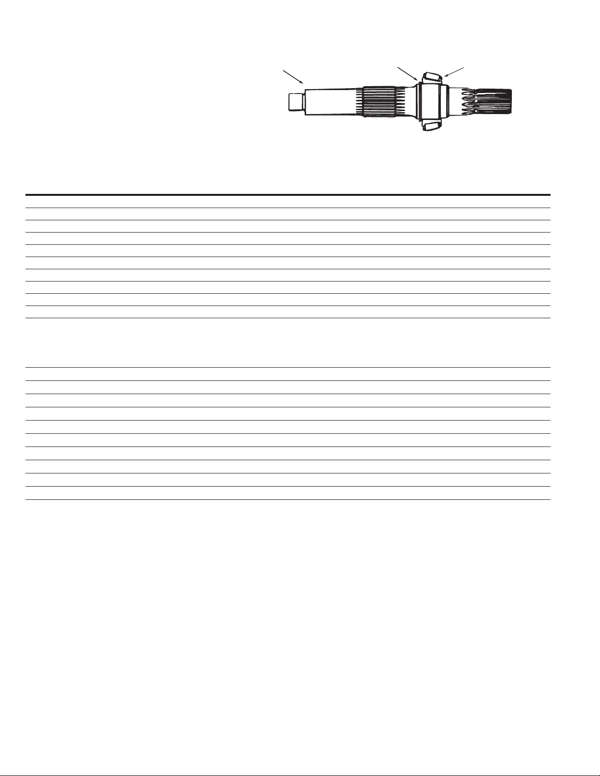
Drive Shaft
(Item 1)
Shaft
Retaining Ring
Bearing Cone
7EATON Series 1 Heavy Duty Hydrostatic Fixed Displacement Motors Parts and Repair E-MOPI-TS002-E September 2004
Table 2.1 Output Drive Shaft Assembly For Motors XX31-XXX (Face Seal Design)
MODEL 3331-3931
SHAFT BEARING RETAINING
ASSEMBLY SHAFT CONE RING DESCRIPTION
103226-000 103229-000 103227-000 103222-188 21 Tooth, 16/32, Pitch Spline
104378-000 104396-000 103227-000 103222-188 14 Tooth, 12/24 Pitch Spline
105197-000 105196-000 103227-000 103222-188 14 Tooth, 12/24 Pitch Spline, Speed Sensor
105353-000 105352-000 103227-000 103222-188 21 Tooth, 16/32, Pitch Spline, Speed Sensor
105380-000 105379-000 103227-000 103222-188 [1.500] Diameter Straight W/ [.3750] X [2.5] Square Key
105391-000 105392-000 103227-000 103222-188 19 Tooth, 16/32, Pitch Spline
105426-000 105427-000 103227-000 103222-188 [1.500] Diameter Straight W/ [.3750] X [2.5] Square Key
105451-000 105450-000 103227-000 103222-188 [1.375] Diameter Taper W/ [.375] X [1.00] Woodruff Key
107519-000 107518-000 103227-000 103222-188 14 Tooth, 12/24 Pitch Spline, 3/8-24
110106-000 110098-000 103227-000 103222-188 23 Tooth, 16/32, Pitch Spline, 3/8-24 UNF x [.75] DP
111122-000 111121-000 103227-000 103222-188 19 Tooth, 16/32, Pitch Spline, Speed Sensor
Model 4631
SHAFT BEARING RETAINING
ASSEMBLY SHAFT CONE RING DESCRIPTION
103579-000 103577-000 103227-000 103222-188 23 Tooth, 16/32, Pitch Spline
104190-000 104192-000 103227-000 103222-188 14 Tooth 12/24, Pitch Spline
105123-000 105121-000 103227-000 103222-188 21 Tooth, 16/32, Pitch Spline, Speed Sensor
105364-000 105365-000 103227-000 103222-188 20 Tooth, 16/32, Pitch Spline, 3/8-24 UNF x [.75] DP
105449-000 105448-000 103227-000 103222-188 19 Tooth, 16/32, Pitch Spline
106910-000 106909-000 103227-000 103222-188 20 Tooth, 16/32, Pitch Spline, Speed Sensor
107315-000 107314-000 103227-000 103222-188 [1.500] Diameter Straight W/ [.3750] X [2.5] Square key, 3/8-24 UNF x [.75] DP
109261-000 109260-000 103227-000 103222-188 14 Tooth 12/24, Pitch Spline, Speed Sensor
110107-000 110099-000 103227-000 103222-188 23 Tooth, 16/32, Pitch Spline, 3/8-24
111052-000 111051-000 103227-000 103222-188 [1.500] Diameter Taper W/ [.375] X [1.00] Square Key
111780-000 111779-000 103227-000 103222-188 19 Tooth, 16/32, Pitch Spline, Speed Sensor
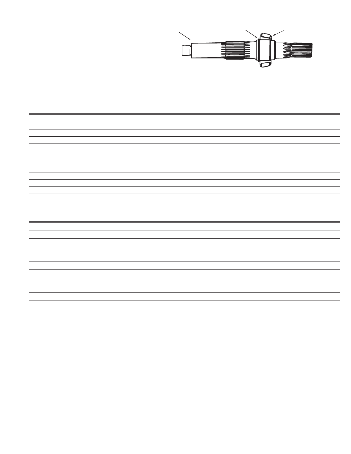
Parts
Drive Shaft
(item 1)
Shaft
Retaining Ring
Bearing Cone
8 EATON Series 1 Heavy Duty Hydrostatic Fixed Displacement Motors Parts and Repair E-MOPI-TS002-E September 2004
Output Drive Shaft Assembly For Motors XX31-XXX (Face Seal Design)
Model 5431
SHAFT BEARING RETAINING
ASSEMBLY SHAFT CONE RING DESCRIPTION
105052-000 105057-000 103808-000 103222-200 14 Tooth 12/24, Pitch Spline
105060-000 105061-000 103808-000 103222-200 21 Tooth, 16/32, Pitch Spline
105070-000 105071-000 103808-000 103222-200 23 Tooth, 16/32, Pitch Spline, Speed Sensor
105170-000 105167-000 103808-000 103222-200 23 Tooth, 16/32, Pitch Spline
105331-000 105332-000 103808-000 103222-200 23 Tooth, 16/32, Pitch Spline W/ 3/8-24 UNF x [.75] DP
105335-000 105336-000 103808-000 103222-200 [1.500] Diameter Straight W/ [.375] X [2.5] Square key
106143-000 106142-000 103808-000 103222-200 21 Tooth, 16/32, Pitch Spline, Speed Sensor
108211-000 108203-000 103808-000 103222-200 [1.500] Diameter Straight W/ [.375] X [2.5] Square Key, 3/8-24 UNF x [.75] DP
110692-000 110691-000 103808-000 103222-200 21 Tooth, 16/32, Pitch Spline W/ 3/8-24 UNF x [.75] DP
111602-000 111601-000 103808-000 103222-200 21 Tooth, 16/32, Pitch Spline W/ M10 X 1.5 threaded hole
MODEL 6431
SHAFT BEARING RETAINING
ASSEMBLY SHAFT CONE RING DESCRIPTION
104640-000 105053-000 103808-000 103222-200 21 Tooth, 16/32, Pitch Spline
105062-000 105063-000 103808-000 103222-200 21 Tooth, 16/32, Pitch Spline
105066-000 105067-000 103808-000 103222-200 23 Tooth, 16/32, Pitch Spline
105270-000 105269-000 103808-000 103222-200 23 Tooth, 16/32, Pitch Spline, Speed Sensor
105356-000 105357-000 103808-000 103222-200 [1.500] Diameter Straight W/ [.3750] X [2.5] Square key
107355-000 107354-000 103808-000 103222-200 [1.500] Diameter Straight W/ [.3750] X [2.5] Square key, 3/8-24 UNF x [.75] DP
107632-000 107631-000 103808-000 103222-200 23 Tooth, 16/32, Pitch Spline, 3/8-24 UNF x[.75] DP
111141-000 111142-000 103808-000 103222-200 [1.500] Diameter Straight W/ [.3750] X [2.5] Square key
111591-000 111590-000 103808-000 103222-200 21 Tooth, 16/32, Pitch Spline, Speed Sensor
113438-000 113437-000 103808-000 103222-200 14 Tooth 12/24, Pitch Spline
Parts
Drive Shaft
(item 1)
Shaft
Retaining Ring
Bearing Cone
9EATON Series 1 Heavy Duty Hydrostatic Fixed Displacement Motors Parts and Repair E-MOPI-TS002-E September 2004
Table 3.0 End Cover Bolt Matrix
ITEM PART
NO. NO. QTY. DESCRIPTION
5 103090-150 2 Hex Head Bolt 3/8-16 GR 8 (models 33/39/46)
5 103091-200 2 Hex Head Bolt 3/8-16 GR 8 (models 54/64)
6 103090-275 4 Hex Head Bolt 3/8-16 GR 8 (models 33/39/46)
6 103091-300 4 Hex Head Bolt 3/8-16 GR 8 (models 54/64)
7 95863-400 4 Hex Head Bolt 3/8-16 GR 5 (Valve Block)
31 104511-300 2 Hex Head Bolt 3/8-16 (Integral Shuttle)
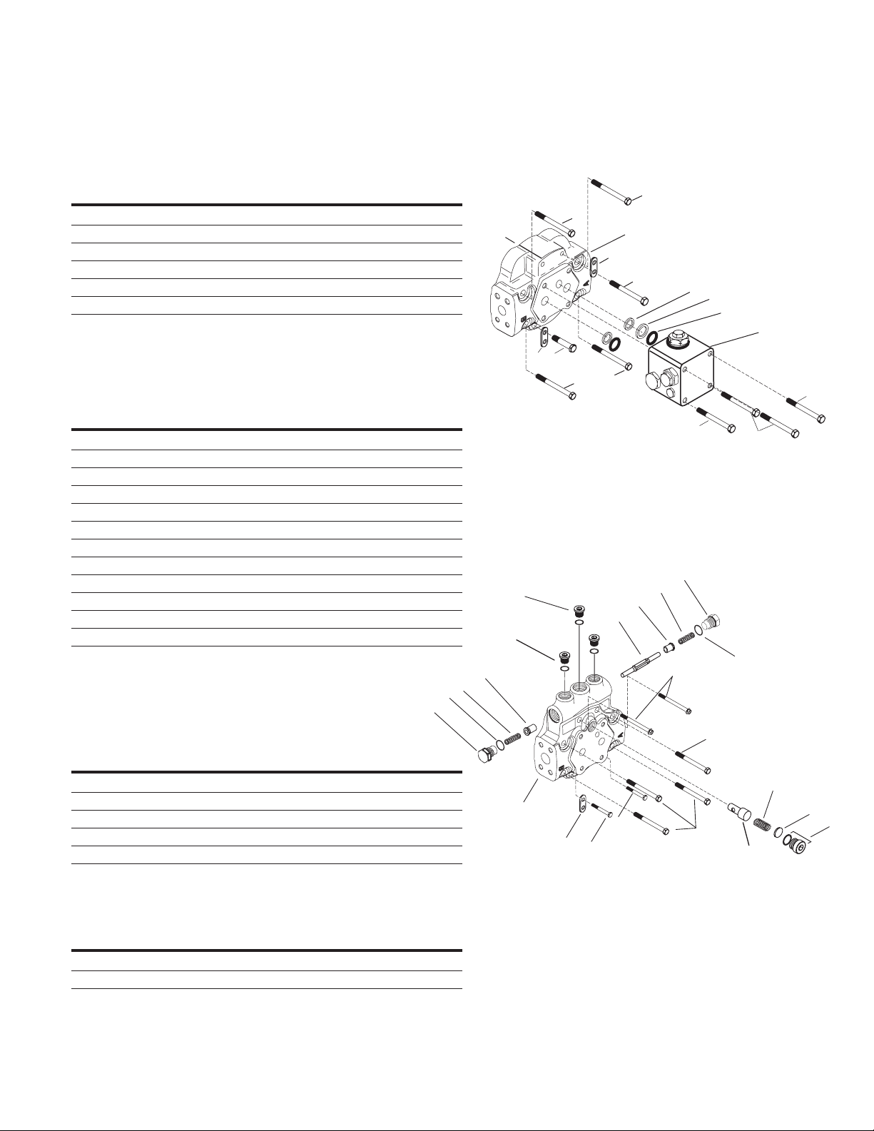
Table 3.1 End Cover with Integral Shuttle and
Low Pressure Relief Valve
ITEM PART
NO. NO. QTY. DESCRIPTION
A 104635-000 2 Shuttle Valve Plug/O-ring
B 101730-00 2 Shuttle Spring (Low–Rate)
B 102530-000 2 Shuttle Spring (High–Rate)
C 101727-000 2 Shuttle Valve
D 102418-000 1 Shuttle Spool
E 25090-008 1 Gauge Port Plug/O-ring
F 25090-006 2 Gauge Port Plug/O-ring
G 104634-000 1 Plunger
H See table 3.3 1 Low Pressure Relief Valve Spring
I 104659-XXX A/R Low Pressure Relief Valve Shims
J 104657-000 1 Low Pressure Relief Valve Plug/O-ring
K 8785-010 2 O-ring
A/R – As Required
Table 3.2 Low Rate Shuttle Valve Service Kit
Motors with Integral Shuttle
Kit No. 990851-000
ITEM PART
NO. NO. QTY. DESCRIPTION
A 104635-000 2 Shuttle Valve Plug/O-ring
B 101730-000 2 Shuttle Spring (Low–Rate)
C 101727-000 2 Shuttle Valve
D 102418-000 1 Shuttle Spool
K 8785-010 2 O-ring
Table 3.3 Low Pressure Relief Valve Spring
(Integral Shuttle Motor Design)
PRESSURE
SPRING P/N SETTING RANGE bar[lbf/in2]
104658-000 11,0 [160]- 16,5[240]
110272-000 19,3[280] - 20,7[300]
Parts
End Cover
(Item 2)
K
A
6
6
6
2
2
24
5
8
10
9
3
5
24
5
6
7
7
A
E
F
C
B
B
C
D
31
7
K
6
H
2
24
5
5
6
G
I
J
10 EATON Series 1 Heavy Duty Hydrostatic Fixed Displacement Motors Parts and Repair E-MOPI-TS002-E September 2004
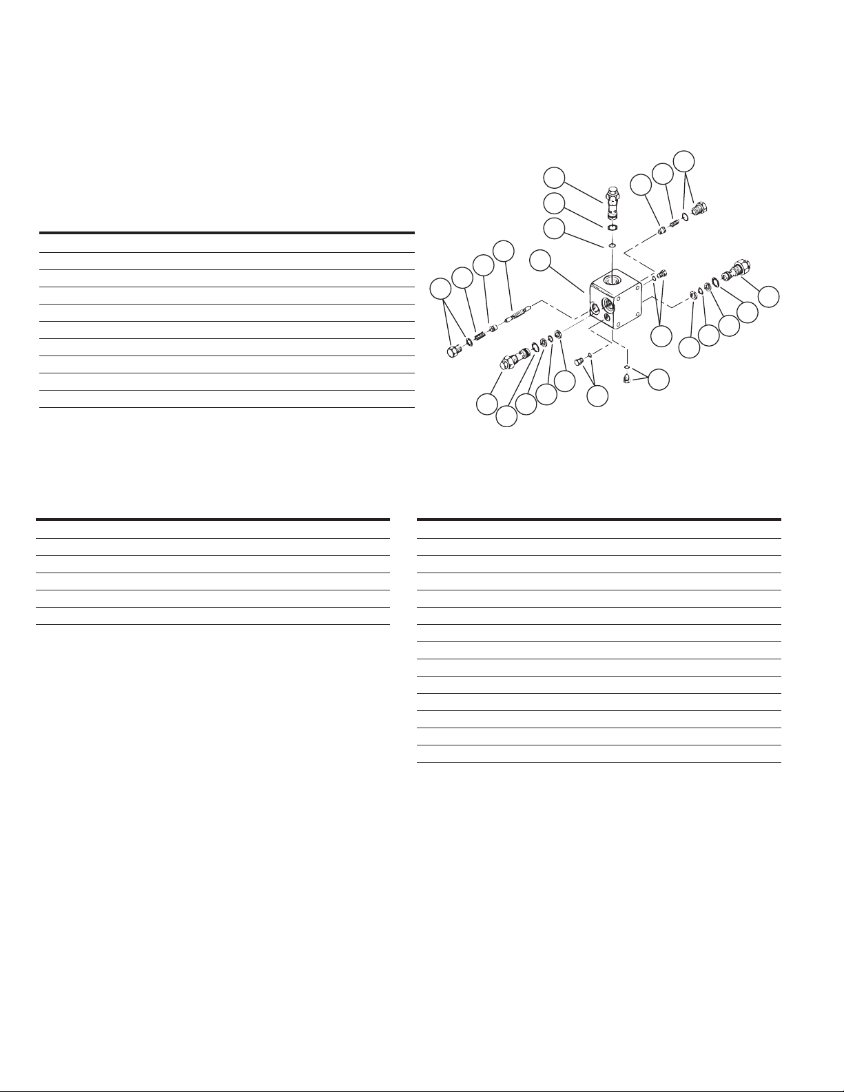
Parts
Valve Block
(Item 3)
Table 4.0 Valve Block Subassembly
ITEM
NO. P/N QTY. DESCRIPTION
A 25090-004 3 Gauge Port Plug/O-ring
B 96083-062 4 Back-up Ring
C 8765-017 3 O-ring
D 8785-010 3 O-ring
E (See Table 4.2) 2 High Pressure Relief Cartridge 101047-XXX
F (See Table 4.2) 1 Low Pressure Relief Cartridge 101048-XXX
G 101727-000 2 Shuttle Valve
H (See Table 4.2) 2 Shuttle Spring
L 101729-000 2 Shuttle Valve Plug/O-ring
J 102418-000 1 Shuttle Spool
Table 4.1
Low Pressure Relief Valve Setting Designation
PART NUMBER-XXX bar [lbf/in2]
XXXXX-016 = 11 [160]
XXXXX-020 = 13,7 [200]
XXXXX-022 = 15,2 [220]
XXXXX-024 = 16,5 [240]
XXXXX-026 = 17,9 [260]
XXXXX-028 = 19,3 [280]
Table 4.2
High Pressure Relief Valve Setting Designation
PART NUMBER-XXX bar [lbf/in2]
XXXXX-150 = 103,4 [1500]
XXXXX-200 = 137,9 [2000]
XXXXX-250 = 172,4 [2500]
XXXXX-300 = 206,8 [3000]
XXXXX-350 = 241,3 [3500]
XXXXX-400 = 275,8 [4000]
XXXXX-450 = 310,3 [4500]
XXXXX-500 = 344,7 [5000]
XXXXX-525 = 379,2 [5200]
XXXXX-550 = 396,4 [5500]
XXXXX-600 = 413,7 [6000]
XXXXX-650 = 448,1 [6500]*
XXXXX-675 = 465,4 [6750]*
*Do not set this pressure level without Eaton Engineering approval
I
F
H
G
D
C
J
I
H
G
3
E
D
B
A
C
B
B
C
B
E
A
A
D
 Loading...