

Eaton 2075 Operation Manual

/'\
1
/~)
;:-1
VI/V
t:, <
OPERATION
EATON
2075
MANUAL
NOISE-GAIN
M B M T MESSTECHNIK
H A N D E L S G H B H
Auf
D - 2 7 2 1 1 B A S S U M
Tel.
ANALYZER
der
04241/3516
A 1 1 o g e
FAX
18
5516
II
_
.
~·
....,
..-.:.T•N
2U/5
~=·
·--··
-
NOISE-GAIN
~IW(O'ZER
'.!.
e .
--
·---~-~
(Y
..
~"
1
-,
1
1
'·
1
!llll•flfllT
--
- -
----~
- 7 8 9
..,,~ -~
~
• 4 5 6
0 1 2 3
~
-
- -
•
1
e
..,
!'oOSf
•<Gl,»~E
E..
:
0,
__
, - „
-.,
••
·-
REVISED
•
-
DECEMBER
1985
Eaton Corporation
Electronic Instrumentation Division
Los Angeles. California 90066
WARRANTY
Eaton
Corporation,
instrument
the
original
Re
pair
or
replacement
our
examination
Electron
Tran
tubes,
potentiometers
authorized
lf
the
instrument
negligence,
void.
This
warranty
IMPLIED
event
SELLER
WARRANTY
shall
neither
connection
With
respect
the
repaired
Electronic
tobe
free
from
purchaser
Electrical
satisfactorily
semiconductors,
are
by
the
factory.
or
any
or
if
any
serial
is in
lieu
the
SELLER
assumes,
with
sales
to
repairs,
portion.
Instrumentation
as
and
(at
defects
follows:
our
Electronic
in
option)
material
Measuring
without
indicates
batteries,
excluded
portion
number
of
all
OF
MERCHANTABILITY,
be
liable
nor
of
instruments
the
from
thereof,
or
other
for
authorizes
foregoing
REPAIR
has
seal
warranties,
INCi
manufactured
warranty
AND
Division,
and
workmanship,
Instruments
eh
arge
that
defects
fuses, lamps,
warranty
been
coverage.
abused, misused,
has
been
express
or
DENTAL
any
person
shall
MAINTENANCE
(SELLER)
effective
...... 1 Year
( F.O.
B.
factory)
are
due
to
workmanship
thermoelements,
Warranty
removed
fitness
OR
CONSEOUENTIAL
to
assume
by
SELLER.
apply
or
or
implied
for a particular
for
for a period
warrants
will
be
returns
damaged
altered,
INCLUDING
it,
any
of
each
after
delivery
effected
or
materials.
and
must
by
accident
the
warranty
purpose.
damages.
other
liability
ninety
new
when
Ratio
first
THE
In
The
days
to
be
or
is
no
in
to
Instruments
the
factory.
instrument
Chargeable
Please
your
provide
instrument:
1.
2.
3.
4.
111
lnclude
data
relevant
data
Additional
and
Service
should
You
will
to
the
factory
repairs:
us
with
Model
Serial
Description
Approximate
was
placed
on
symptoms.
service
information
Centers:
be
returned
be
advised
prepaid.
lf
requested,
the
or
Type
Number
of
date
in
measurements
Elmhurst,
Fairfield,
Los
Oakton,
Sunnyvale,
only
of
detailed
Validity
an
following
trouble
instrument
operation.
taken.
can
be
IL
NJ
Angeles,
VA
on
prior
authorization
shipping
of
warranty
estimate
of
information
5.
(1) 6.
7.
suspected
locat1on
SERVICE
made
available
(312)
(201)
CA -
(213)
(703)
CA (408)
from
instructions
will
be
charges
in
order
will
to
expedite
Approximate
hours
in use.
Maintenance
requested
Other
ot
trouble.
by
calling
comments.
ma1ntenance
279-8220
227-8990
822-3061
620-5820
733-657
4
the
Representative
at
that
determined
be
made
the
number
action
or
performed
act1on
any
of
these
time.
Return
by
the
prior
to
processing
of
previously
taken
and
Eaton
or
the
factory.
repairs.
of
any
other
Sales
FRANCE • Argenteuil • Telephone:
UNITED
KINGOOM • Wokingham • Telephone:
GERMANY • Munich • Telephone:
(03)
(089)
99817
446
(0734)
794717
5233023-24
• Telex:
• Telex:
• Telex:
609036
847238
529420

EATON2075
TABLE OF CONTENTS
TABLE OF CONTENTS
Paragraph
1-1
1-2
1-3
1-4
1-5
1-6
1-7
1-8
1-9
2-1
2-2
2-3
2-4
2-5
2-6
2-7
2-8
2-9
2-10
2-11
SECTION
Scope and Organization
Introduction
Purpose and U se
Calibration Cycle
Equipment Supplied
Equipment Required But Not Supplied
Optional Accessories
Specifications
Safety Precautions
SECTION
Introduction
U npacking and Physical Inspection
AC Power Requirements
Operational Inspection
Operating Temperature
Selection
Equipment Mounting
Rack Mounting the Eaton 2075
Equipment Interconnections
Reference Card
Pre-Operational Adjustments
1-GENERAL
.........................................................
of
.....................................................
........................................................
....................................................
2-
INSTALLATION
.........................................................
of
Relay DC Voltage
......................................................
INFORMATION
of
the Manual
Equipment.
...................................................
..................................................
...............................................
.................................................
................................................
..................................................
.........................................
......................................
..........................................
..........................................
............................................
...........................................
Tide
....................................
....................................
1-1
.
.
1-2
1-2
.
.
1-2
.
1-3
1-3
.
.
1-3
.
1-4
.
1-7
.
2-1
.
2-1
.
2-1
.
2-3
.
2-5
.
2-3
.
2-5
.
2-5
.
2-7
.
2-8
.
2-8
3-1
3-2
3-3
3-4
3-5
3-6
3-7
3-8
3-9
3-10
3-11
3-12
3-13
3-14
3-15
3-16
3-17
SECTION 3 - OPERATION
Introduction
Capabilities
Controls and Indicators
Power-On Conditions, Preset, and Total System Reset
Continuous Measurement Mode and the Hold Function
Fixed Frequency Operation
Swept Frequency Operation
Uncorrected and Corrected Measurements
of
Entry
Selecting the
Procedure for Test Configuration 1
Procedure for Test Configuration 2 - Double Sideband
Procedure for Test Configuration 2 - Single Sideband
Procedure for Test Configuration
Procedure for Test Configuration
Procedure for Test Configuration
Procedure for Test Configuration
.........................................................
of
the Eaton 2075
Frequency and
Correct
Test Configuration
................................................
ENR
..........................................
.............................................
............................................
Values
.....................................
..................................
......................................
3-
Single Sideband
4-
Double Sideband
4-
Single Sideband
5-
Single Sideband
................................
.......................
......................
......................
.......................
.......................
......................
.......................
.......................
.
3-1
.
3-1
.
3-3
.
3-16
.
3-20
.
3-21
.
3-22
.
3-24
.
3-26
.
3-27
.
3-31
.
3-33
.
3-37
.
3-41
.
3-45
.
3-49
3-53
.
TABLE OF CONTENTS EATON 2075
TABLE OF CONTENTS (Continued)
Paragraph
3-18
3-19
3-20
3-21
3-22
3-23
3-24
3-25
3-26
3-27
3-28
3-29
3-30
3-31
3-32
3-33
3-34
3-35
3-36
3-37
3-38
3-39
3-40
3-41
3-42
3-43
3-44
3-45
3-46
3-47
3-48
3-49
3-50
3-51
Title
6-
Procedure for Test Configuration
of
Additional Types
Measurements
Single Sideband
.......................................
Effective Input Noise Temperature (Te) Measurement
Y-Factor (Y) Measurement
Operating Noise Temperature (T
Power (dB) Measurements
ENR
Measurement
...................................................
Noise Measure (M) Measurement
Manual Measurements
Manual Measurement
Manual Measurement
Calibrated Noise Source
Noise Drive Voltage and Indicator
ENR
Tables
Calibration
.........................................................
..........................................................
Frequency Calibration
Second Stage Calibration
Input Gain Selection
IF Attenuators Calibration
of
Selection
Sideband Parameters
Bandwidth Compensation
Determining the Bandwidth Ratio
For
Compensation
Tcold Compensation
Loss
...................................................
Oscilloscopes and Recorders to Display Data
Selecting an External Local Oscillator
Controlling External Local Oscillators
Writing a Custom Program
Special Functions
Error
Messages
.....................................................
......................................................
Store-Recall Registers
Smoothing Function
100
kHz Display Resolution
Software Revisions
...................................................
...................................................
.............................................
p) Measurement
0
..........................
.............................................
.......................................
.................................................
of
Noise Figure and Gain
of
Y-Factor
.......................................
............................
...............................................
.......................................
.................................................
..............................................
..................................................
.............................................
........................................
..............................................
of
the First and Second Stages
or
Gain
.........................................
..............................
....................................
....................................
For
Controlling a Local Oscillator
.................................................
............................................
.......................
.......................
..............
................
3-57
.
.
3-62
3-63
.
.
3-63
3-64
.
.
3-65
.
3-66
.
3-67
.
3-67
.
3-67
.
3-69
.
3-70
3-71
.
3-72
.
.
3-74
3-74
.
.
3-75
.
3-77
3-78
.
.
3-78
.
3-82
.
3-84
.
3-86
3-88
.
.
3-89
3-95
.
.
3-95
.
3-96
3-101
.
.
3-106
3-110
.
3-110
.
3-113
.
3-113
.
ii
EATON 2075
TABLE OF CONTENTS
TABLE OF CONTENTS (Continued)
Paragraph
4-1
4-2
4-3
4-4
4-5
4-6
4-7
4-8
4-9
4-10
4-11
5-1
5-2
5-3
5-4
5-5
5-6
5-7
5-8
5-9
5-10
SECTION
Introduction
GPIB General Information
GPIB Operating Modes
Setting the GPIB Address
GPIB Compatibility
Remote and Local Modes
GPIB Message Types
Interface Bus Messages
Device Messages
Data Messages
Status Messages
SECTION
Introduction
Test Equipment Required
Performance Verification Procedures
Power-On Test
Noise Drive Voltage Test
IF Attenuators Calibration
Final Detector Bias Test
Second Stage Calibration
Final Detector Linearity Test
Scope/Plotter Output Test
4-GPIB
.........................................................
5-
.........................................................
OPERATION
.............................................
................................................
..............................................
...................................................
..............................................
.................................................
................................................
.....................................................
.......................................................
......................................................
PERFORMANCE VERIFICATION TESTS
..............................................
.......................................................
...............................................
.............................................
...............................................
..............................................
...........................................
..........................
Title
.....................................
,
...................
.
4-1
.
4-1
.
4-3
.
4-3
.
4-3
.
4-4
.
4-4
.
4-4
.
4-8
.
4-12
.
4-16
.
5-1
.
5-1
.
5-2
.
5-2
.
5-2
.
5-3
.
5-3
.
5-4
.
5-5
.
5-7
iii
LIST OF ILLUSTRATIONS
EATON 2075
LIST OF ILLUSTRATIONS
Title
1-1
2-1
2-2
2-3
2-4
2-5
3-1
3-2
3-3
3-4
3-5a
3-5b
3-6
3-7a
3-7b
3-8a
3-8b
3-9a
3-9b
3-lOa
3-lOb
3-lla
3-1
lb
3-12a
3-12b
3-13a
3-13b
3-14a
3-14b
3-15a
3-15b
3-16
3-17
3-18
3-19
3-20
3-21
3-22
3-23
3-24
3-25
Eaton 2075 Noise Gain Analyzer
AC Voltage Selection Card
Extemal Relay Voltage Selection
of
Installation
Installation
GPIB Connector
Rack Mounts
of
Slide Mounts
.....................................................
Front Panel Controls and Indicators
Rear Panel Controls and lndicators
Uncorrected and Corrected Measurements
Test Configuration Downconversion Modes
1-
Test Configuration
Test Configuration
Calibration
1-
Extemal Relays for Calibration
........................................
.............................................
........................................
............................................
............................................
......................................
......................................
................................
...............................
.......................................
Test Configuration 1 - Extemal Relays for Calibration
Test Configuration 2 - Calibration - Double Sideband
Test Configuration
Test Configuration 2
Measurement-
-Calibration
Double Sideband
- Single Sideband
2-
Test Configuration 2 - Measurement - Single Sideband
Test Configuration 3
-Calibration
Test Configuration 3 - Measurement
.......................................
.....................................
Test Configuration 4 - Calibration - Double Sideband
4-
Test Configuration
Test Configuration
Test Configuration 4 Test Configuration 5
Test Configuration 5 - Measurement
Test Configuration
Test Configuration
P
Setup-Calibration
T
0
~P
T
ENR
ENR
Setup-
Measurement
Setup-Calibration
Setup-Measurement
Manual Y-Factor Measurement
of
Example
ENR
Calibrated Noise Source Data
Table
1,
2,
Setup With Extemal Relays for Calibration
Example 1 Sideband Selection
Example 2 Sideband Selection
Example 3 Sideband Selection
Example 4 Sideband Selection
Bandwidth Compensation Example 1
Bandwidth Compensation Example 2
Measurement - Double Sideband
4-
Calibration - Single Sideband
Measurement-
-Calibration
Single Sideband
.......................................
.....................................
6-
Calibration
6-
Measurement
.......................................
.....................................
................................................
..............................................
...............................................
.............................................
..........................................
.................................
or 3 ..................................................
................................
..........................................
..........................................
..........................................
..........................................
.....................................
.....................................
.......................
.......................
.......................
......................
........................
......................
.......................
......................
........................
......................
.
1-1
.
2-2
.
2-4
.
2-5
.
2-6
.
2-8
.
3-4
3-15
.
.
3-25
.
3-30
.
3-31
.
3-31
.
3-31
.
3-34
.
3-34
.
3-38
3-38
.
.
3-42
.
3-42
.
3-46
.
4-36
.
3-50
.
3-50
3-54
.
.
3-54
.
3-58
.
3-59
3-64
.
3-64
.
.
3-66
.
3-66
.
3-69
.
3-71
.
3-73
.
3-76
.
3-79
.
3-80
.
3-81
.
3-81
.
3-82
.
3-83
iv
EATON 2075
LIST OF ILLUSTRATIONS
LIST OF ILLUSTRATIONS (Continued)
Title
3-26
3-27
3-28
3-29
3-30
3-31
3-32
4-1
4-2
4-3
4-4
4-5
4-6
4-7
4-8
4-9
4-10
5-1
Insertion Loss Measurement With Power Meter
Insertion Loss Measurement With 2075
Loss Compensation
Error
Caused by
...................................................
Tcold
Deviation From 290 K
Test Pattern 2 Oscilloscope Display
...................................
......................................
Noise Figure and Gain Oscilloscope Display
Smoothing Indicator
General Purpose Interface Bus
Sample Data Output
Status Byte
..........................................................
..................................................
..........................................
..................................................
............................
..............................
...............................
Flowchart For Data Collection in Test Configuration 1 Using SRQ Data Ready
Programming Example For Data Collection in Test Configuration 1 Using SRQ
On Data Ready With HP 85 Controller
From
Sample Results
Program
Setup in Test Configuration 2
Flowchart For SRQ on Ready
of
...........................................
To
Flowchart For SRQ on Data Ready
Sample Program
Output Test Pattern 2
.....................................................
..................................................
...................................
Figure 4-5
Tune
..............................
...................................
......................................
..
3-84
.
.
3-85
.
3-87
.
3-89
.
3-91
.
3-92
.
3-111
.
4-2
.
4-14
.
4-17
.
4-18
.
4-19
.
4-21
.
4-21
.
4-23
.
4-26
.
4-28
.
5-8
V
LIST
OF T ABLES
LIST OF TABLES
EATON
2075
Table
1-1
1-2
1-3
1-4
2-1
3-1
3-2
3-3
3-4
3-5
3-6
3-7
3-8
3-9
3-10
4-1
4-2
4-3
4-4
4-5
Title
Equipment Supplied
Optional Accessories
Performance Specifications
Supplemental Specifications
GPIB Connector Pin-out
Front Panel Controls and Indicators
Rear Panel Controls and Indicators
Power-On, Preset, and Total System Reset Parameters
Selecting the
Additional Types
Output Display Special Functions
Control Programs For Externat Local Oscillators
ASCII Codes
Special Functions
Error
Messages
GPIB Functional Capabilities
GPIB Function Reference Table
Eaton 2075 GPIB Device Codes
Eaton 2075 GPIB Front Panel Codes
Selection
Correct
of
Data Message Contents
...................................................
..................................................
.............................................
............................................
...............................................
......................................
......................................
Test Configuration
of
Measurements
........................................
........................................................
.....................................................
......................................................
...........................................
.........................................
.........................................
..................................
.......................................
...........................
.....................................
......................................
.......................
.
1-3
.
1-3
.
1-4
.
1-6
.
2-8
.
3-5
.
3-15
.
3-18
.
3-29
.
3-62
.
3-90
.
3-95
.
3-99
.
3-102
.
3-107
.
4-4
4-6
.
.
4-9
4-11
.
4-12
.
vi
EATON
2075
GENERAL INFORMATION
SECTION 1
GENERAL INFORMATION
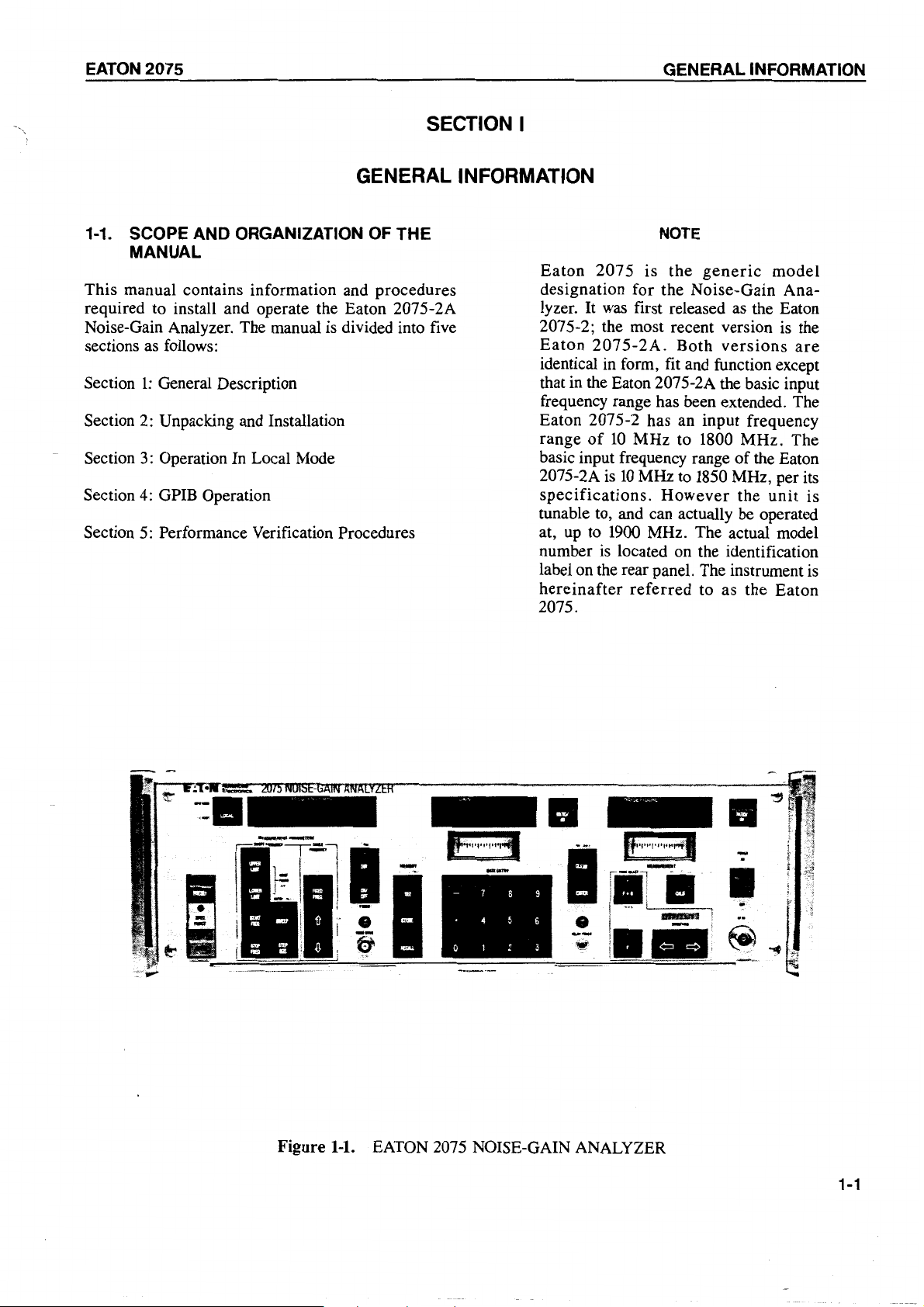
1-1.
SCOPE AND ORGANIZATION OF THE
MANUAL
This manual contains information and procedures
required to install and operate the Eaton 2075-2A
Noise-Gain Analyzer. The rnanual is divided into five
as
sections
Section
Section
Section
follows:
1:
General Description
2:
Unpacking and Installation
3:
Operation In Local Mode
Section 4: GPIB Operation
5:
Section
Performance Verification Procedures
NOTE
Eaton
2075
is
the
generic
rnodel
designation for the Noise-Gain Ana-
lt
was
lyzer.
first released
as
the Eaton
2075-2; the most recent version is the
Eaton
identical in form,
2075-2A.
Both
versions
fit
and function except
are
that in the Eaton 207 5-2A the basic input
frequency range has been extended. The
Eaton 2075-2 has an input frequency
of
10
range
basic input frequency range
2075-2A
specifications.
MHz to 1800 MHz. The
of
the Eaton
is
10
MHz to
1850
However
MHz, per its
the
unit
is
tunable to, and can actually be operated
1900
at, up to
nurnber
is
MHz. The actual rnodel
located on the identification
label on the rear panel. The instrurnent is
hereinafter
referred
to as the Eaton
2075.
Figure
1-1.
EATON
- 7 8 9
• 4 5 6
0 1 2 3
2075 NOISE-GAIN ANALYZER
1-1
GENERAL INFORMATION
EATON
2075
This manual has been organized to allow the new user
of
the Eaton 2075 to quickly and easily begin test
to
operations. Read Section 1
the test instrument. Follow the procedures
obtain a familiarity with
of
Section 2
for installation.
The
Eaton
configurations,
2075
can
be
used
depending
on
in any
the
desired
of 6 test
test
application. Section 3 is organized to quickly bring the
user
to
the
correct
procedure. Figure
3-1
and Table
test
configuration
3-1
may
be studied to
and
its
obtain a familiarity with the controls and indicators.
Paragraph
3-10 and Table
3-4
guide
the
user
in
selecting the correct test configuration. Paragraphs 3-
11
through
3-18
are the procedures to
be
used with
each configuration. Each procedure includes the
keystroke sequences necessary for each step. The
remaining pages of Section 3 cover, in greater detail,
of
specific subjects relevant to operation
Section 4 covers operation when the 2075
by an
external
computer
via
a General
the 2075.
is
controlled
Purpose
Interface Bus.
Section 5 includes information and procedures used
verify that the 2075
1-2. INTRODUCTION
This
section
description
including:
of
purpose
is
performing correctly.
of
the
manual
contains a general
the Eaton 2075 Noise-Gain Analyzer
and
function,
equipment
to
requirements, available options, specifications, and
safety precautions.
The analyzer can make the following measurements:
Corrected Noise Figure and Gain
Uncorrected Noise Figure
(F
(F)*
+ G)*
Corrected Effective Input Noise
Temperature and Gain
Effective Input Noise Temperature
Corrected Effective Operating Noise
Temperature and Gain
Effective Operating Noise Temperature
(T
P + G)
0
(Top)
Noise Measure (includes Gain) (M)*
1900
(Y)*
(PWR
(ENR)*
of
the 2075
MHz. In
dB)*
its
Y Factor
Power
Excess Noise Ratio
in
dB
or
as
*Can be displayed
a dimensionless ratio
The specified input frequency range
10
extends from
is
actually tunable and operable to
MHz to
1850
MHz. However, the unit
simplest test configuration the analyzer will make
measurements of RF devices with output frequencies
in this range. More complex test configurations,
of
requiring one or two stages
s ion, allow measurements
as
high
as
frequencies
65.535 GHz. The 2075 has the
capability for controlling the local oscillator used
external downconver-
of
devices with output
in
the external downconversion process.
1-4. CALIBRATION
CYCLE
1-3. PURPOSE AND
USE
OF
EQUIPMENT
The 2075 Noise-Gain Analyzer is a programmable,
microprocessor-controlled
specifically to make precise measurements
and gain characteristics
in
can be controlled
controls,
or
controller via
its local mode using its front panel
in the remote mode, by an external
an
IEEE-488 GPIB (General Purpose
instrument
designed
of
of
RF devices. The analyzer
noise
Interface Bus).
1-2
At six month intervals the Performance Verification
of
Procedures in Section 5
performed
performance
to
ensure
of
the 207 5.
this manual should be
the
continued
optimum
At one year intervals the instrument should be fully
calibrated
using
the
alignment
and
adjustment
procedures from the maintenance manual. These
procedures
should
be
performed
by
qualified
personnel experienced in calibration and servicing of
electronic instrumentation.
EATON
2075
GENERAL INFORMATION
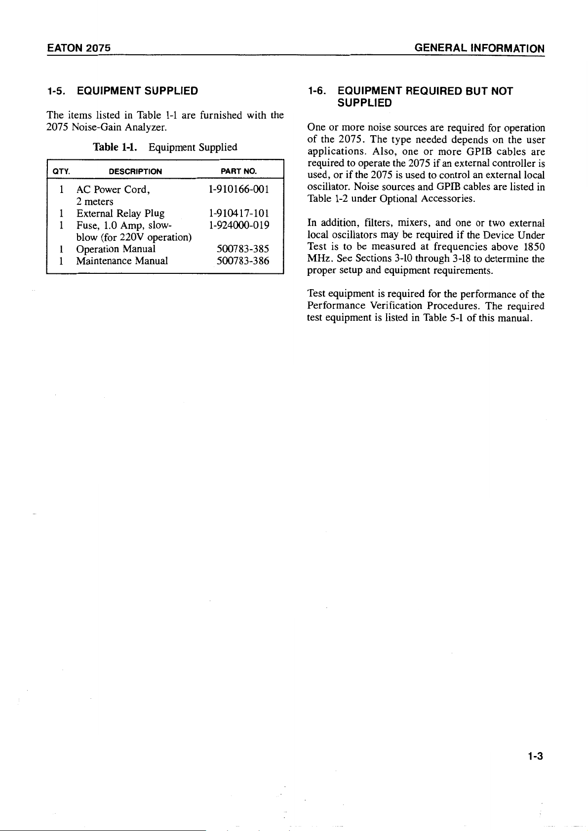
1-5. EQUIPMENT SUPPLIED
The items listed in Table
1-1
are furnished with the
2075 Noise-Gain Analyzer.
Table
QTY. DESCRIPTION PART NO.
1
AC
1-1.
Power Cord,
Equipment Supplied
1-910166-001
2 meters
External Relay Plug
1
1
Fuse,
1.
0 Amp, slow- 1-924000-019
1-910417-101
blow (for 220V operation)
Operation Manual 500783-385
1
Maintenance Manual 500783-386
1
1-6. EQUIPMENT REQUIRED BUT NOT
SUPPLIED
One or more noise sources are required for operation
of
the 207 5. The type needed depends on the user
applications. Also, one
required to operate the 2075
used, or
if
the 2075 is used to control an external local
oscillator. Noise sources and GPIB cables are listed
Table
1-2
under Optional Accessories.
In
addition, filters, mixers, and one or two external
local oscillators
may
be
required
or
more GPIB cables are
if
an external controller
if
the Device Under
is
in
Test is to be measured at frequencies above 1850
MHz. See Sections
3-10
through
3-18
to determine the
proper setup and equipment requirements.
Test equipment is required for the performance
of
the
Performance Verification Procedures. The required
test equipment is listed in Table
5-1
of
this manual.
1-3
GENERAL INFORMATION
EATON 2075
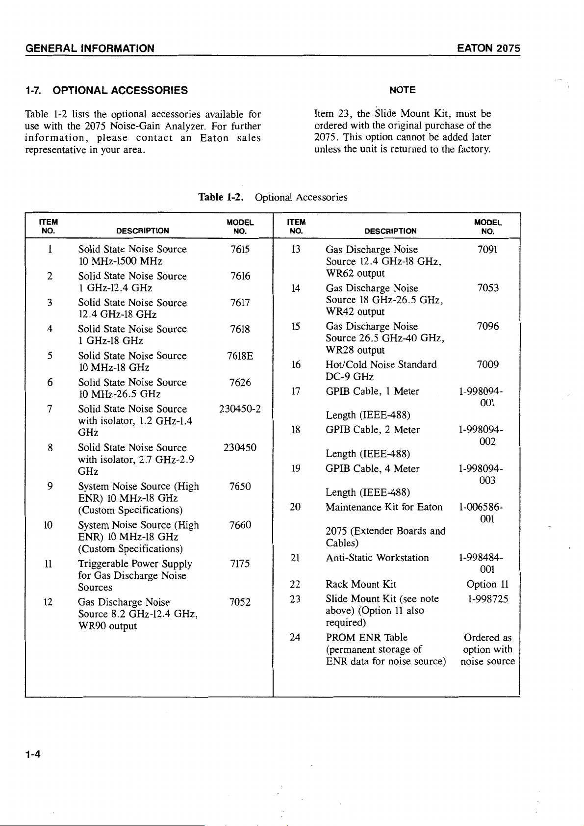
1-7.
OPTIONAL ACCESSORIES
Table
1-2
lists the optional accessories available for
use with the 2075 Noise-Gain Analyzer. For further
inforrnation,
please
contact
an
Eaton
sales
representative in your area.
Table 1-2. Optional Accessories
ITEM
NO.
1
Solid State Noise Source
10
DESCRIPTION
MHz-1500 MHz
2 Solid State Noise Source
MODEL ITEM MODEL
NO.
7615
7616
1 GHz-12.4 GHz
3 Solid State Noise Source
7617
12.4 GHz-18 GHz
4 Solid State Noise Source
1
5
6
7
GHz-18
Solid State Noise Source
10
MHz-18 GHz
Solid State Noise Source
10
MHz-26.5 GHz
Solid State Noise Source
with isolator,
GHz
1.2
GHz-1.4
7618
7618E
7626
230450-2
GHz
8 Solid State Noise Source 230450
with isolator, 2.7 GHz-2.9
GHz
9
System Noise Source (High 7650
10
ENR)
MHz-18 GHz
(Custom Specifications)
10
System Noise Source (High
ENR)
10
MHz-18 GHz
7660
(Custorn Specifications)
11
Triggerable Power Supply
7175
for Gas Discharge Noise
Sources
12
Gas Discharge Noise
7052
Source 8.2 GHz-12.4 GHz,
WR90 output
NOTE
Itern 23, the Slide Mount Kit, rnust be
ordered with the original purchase
2075. This option cannot be added later
unless the unit is returned to the factory.
NO.
13
Gas Discharge Noise
Source 12.4
DESCRIPTION NO.
GHz-18
GHz,
WR62 output
14
Gas Discharge Noise 7053
Source
18
GHz-26.5 GHz,
WR42 output
15
Gas Discharge Noise 7096
Source 26.5 GHz-40 GHz,
WR28 output
16
Hot/Cold Noise Standard 7009
DC-9 GHz
17
GPIB Cable, 1 Meter 1-998094-
Length (IEEE-488)
18
GPIB Cable, 2 Meter 1-998094-
Length (IEEE-488)
19
GPIB Cable, 4 Meter 1-998094-
Length (IEEE-488)
20
Maintenance Kit for Eaton
2075 (Extender Boards and
Cables)
21
22
23
Anti-Static Workstation 1-998484-
Rack Mount Kit Option
Slide Mount Kit (see note
11
above) (Option
also
required)
24
PROM ENR Table Ordered
(permanent storage
of
ENR data for noise source)
of
the
7091
001
002
003
1-006586-
001
001
11
1-998725
as
option with
noise source
1-4
EATON
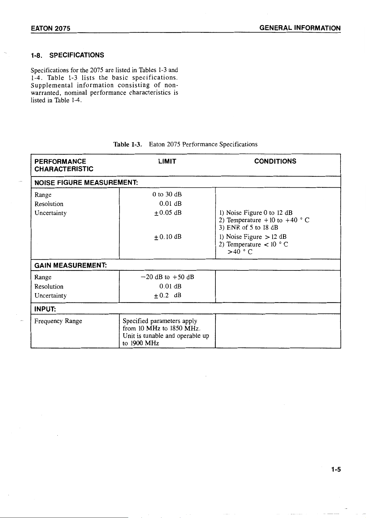
1-8. SPECIFICATIONS
2075
GENERAL
INFORMATION
Specifications for the 2075 are listed in Tables
1-4.
Table
Supplemental
1-3
lists
information
the
basic
specifications.
consisting
of
1-3
nonwarranted, nominal performance characteristics
listed in Table 1-4.
Table 1-3. Eaton 2075 Performance Specifications
PERFORMANCE
CHARACTERISTIC
NOISE FIGURE MEASUREMENT:
Range
Resolution
U ncertainty
LIMIT
0 to 30
0.01
±0.05
±0.10
and
is
dB
dB
dB
dB
CONDITIONS
1)
Noise Figure 0 to
2)
Temperature +
3) ENR of 5 to
1)
Noise Figure >
2)
Temperature <
>40
° c
18
10
dB
12
10
12
to
dB
° C
dB
+40
° C
GAIN MEASUREMENT:
Range
Resolution
U ncertainty
INPUT:
Frequency Range
-20
dB
to
+50
dB
dB
0.01
±0.2
dB
Specified parameters apply
from
10
MHz to
1850
MHz.
Unit is tunable and operable up
to 1900 MHz
1-5
GENERAL INFORMATION EATON
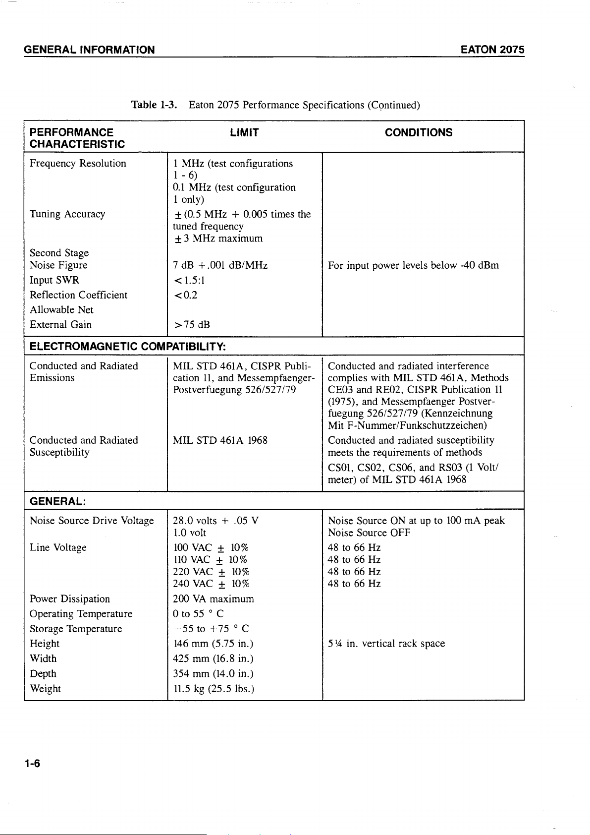
Table 1-3. Eaton 2075 Performance Specifications (Continued)
2075
PERFORMANCE
CHARACTERISTIC
Frequency Resolution
1 MHz (test configurations
1 -
6)
0.1
MHz (test configuration
LIMIT CONDITIONS
1 only)
Tuning Accuracy
± (0.5 MHz + 0.005 times the
tuned frequency
± 3 MHz maximum
Second Stage
Noise Figure
Input SWR
Reflection Coefficient
Allowable Net
External Gain
ELECTROMAGNETIC COMPATIBILITY:
Conducted and Radiated
Emissions
Conducted and Radiated
Susceptibility meets the requirements
+.
001
7 dB
1.5:1
<
dB/MHz For input power levels below -40 dBm
<0.2
>75
dB
MIL STD 461A, CISPR Publication
11,
and Messempfaenger-
Postverfuegung 526/527179
MIL STD 461A
1968
Conducted and radiated interference
complies with MIL STD 461A, Methods
CE03 and RE02, CISPR Publication
(1975), and Messempfaenger Postverfuegung 526/527 /79 (Kennzeichnung
Mit F-Nummer/Funkschutzzeichen)
Conducted and radiated susceptibility
CSOl, CS02, CS06, and RS03
meter)
of
MIL STD 461A
of
methods
1968
(1
11
Volt/
GENERAL:
Noise Source Drive Voltage
28.0 volts + .05 V Noise Source ON at
1.0 volt Noise Source OFF
Line Voltage
Power Dissipation 200
Operating Temperature 0 to
Storage Temperature
Height
100
VAC ± 10%
110
VAC ± 10%
VAC ± 10%
220
240
VAC ± 10%
VA
maximum
55
° C
-55
to
+75
° C
146
mm (5.75 in.) 5
Width 425 mm (16.8 in.)
Depth 354 mm (14.0 in.)
Weight
1-6
11.5
kg
(25.5 lbs.)
up
48 to 66 Hz
48 to 66 Hz
48 to 66 Hz
48 to 66 Hz
1
A in. vertical rack space
to
100
mA
peak
EATON
2075 GENERAL INFORMATION
CHARACTERISTIC
Bandwidth
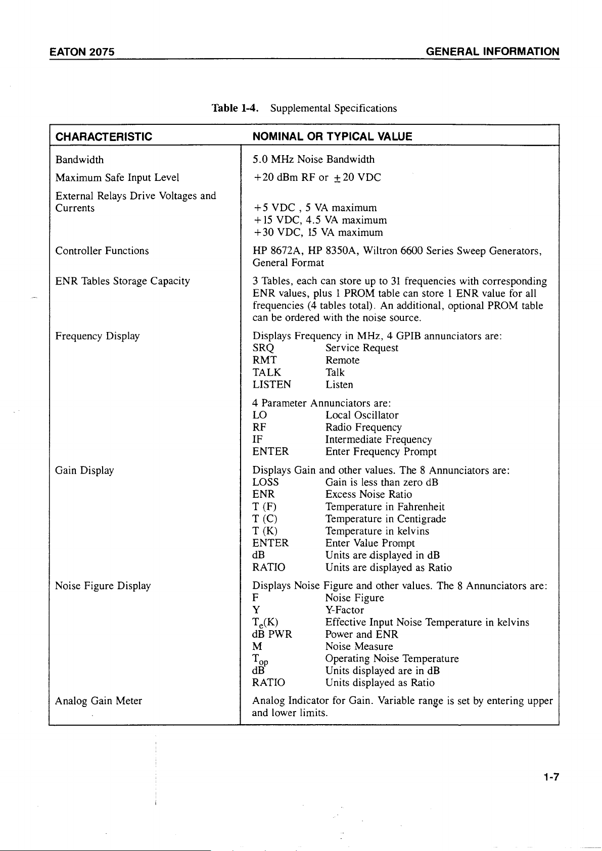
Table 1-4. Supplemental Specifications
OR
NOMINAL
5.0
MHz Noise Bandwidth
TYPICAL
VALUE
Maximum Safe Input Level
+20
dBm RF or
±20
VDC
External Relays Drive Voltages and
Currents
VDC, 5 VA
+
15
VDC,
+30
VDC,
4.5
15
maximum
VA
maximum
VA
maximum
+5
Controller Functions HP 8672A, HP 8350A, Wiltron 6600 Series Sweep Generators,
General Format
31
ENR Tables Storage Capacity 3 Tables, each can store up to
frequencies with corresponding
ENR values, plus 1 PROM table can store l ENR value for all
frequencies (4 tables total). An additional, optional PROM table
can be ordered with the noise source.
Frequency Display
Displays Frequency in MHz, 4 GPIB annunciators are:
SRQ
Service Request
RMT Remote
TALK Talk
LISTEN Listen
4 Parameter Annunciators are:
LO Local Oscillator
RF Radio Frequency
IF
Intermediate Frequency
ENTER Enter Frequency Prompt
Gain Display
Displays Gain and other values. The 8 Annunciators are:
LOSS Gain
is
less than zero
dB
ENR Excess Noise Ratio
T (F)
(C)
T
T (K)
Temperature in Fahrenheit
Temperature
Temperature
in
Centigrade
in
kelvins
ENTER Enter Value Prompt
dB
RATIO
Units are .displayed in
dB
Units are displayed as Ratio
Noise Figure Display
Analog Gain Meter
Displays Noise Figure and other values. The 8 Annunciators are:
F Noise Figure
y
Te(K)
dBPWR
Y-Factor
Effective Input Noise Temperature
Power and ENR
in
kelvins
M Noise Measure
Top
dB
Operating Noise Temperature
Units displayed are
in
dB
RATIO Units displayed as Ratio
Analog Indicator for Gain. Variable range
is
set
by
entering upper
and lower limits.
1-7
GENERAL INFORMATION
EATON
2075
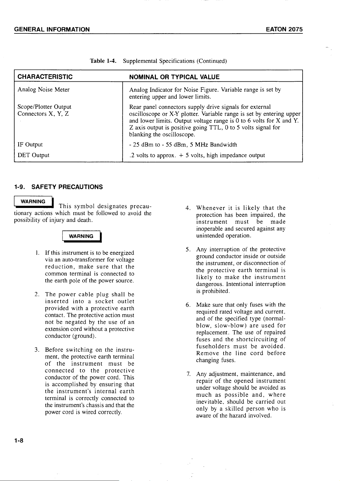
Table 1-4.
CHARACTERISTIC
Analog Noise Meter
Supplemental Specifications (Continu.ed)
NOMINAL
OR
TYPICAL
VALUE
Analog Indicator for Noise Figure. Variable range is set by
entering upper and lower limits.
Scope/Plotter Output
Y,
Connectors X,
Z
Rear panel connectors supply drive signals for external .
or
X-Y
oscilloscope
plotter. Variable range is set by entermg upper
and lower limits. Output voltage range
z axis output
is
positive going
TTL,
0 to 5 volts signal for
blanking the oscilloscope.
IF Output - 25 dBm to - 55 dBm, 5 MHz Bandwidth
DET Output
.2 volts to approx.
+ 5 volts, high impedance output
1-9. SAFETY PRECAUTIONS
WARNING 1 . l d .
1
tionary actions which must be followed to avoid the
possibility
Th1s
of
injury and death.
symbo
es1gnates
precau-
Whenever
4.
protection has been impaired, the
instrument
inoperable and secured against any
1 WARNING 1
unintended operation.
is
0 to 6 volts for X and
it
is
likely
must
be
that
made
Y.
the
1.
If
this instrument is to be energized
via an auto-transformer for voltage
reduction,
make
sure
common terminal is connected to
of
the earth pole
The
2.
power
inserted
provided with a
the power source.
cable
plug
into a socket
protective
contact. The protective action must
not be
negated
by the use
extension cord without a protective
conductor (ground).
3.
Before
switching
on the
ment, the protective earth terminal
of
the
instrument
connected
conductor
to
of
the power cord. This
is accomplished
the
instrument's
terminal
is
correctly connected to
the
by
must
protective
ensuring that
internal
the instrument's chassis and that the
is
power cord
wired correctly.
that
shall
outlet
earth
of
instru-
earth
the
be
an
be
of
5. Any interruption
ground conductor inside
the instrument,
the
protective
likely
to
make
the protective
or
or
disconnection
earth
terminal
the
instrument
outside
of
is
dangerous. Intentional interruption
is
prohibited.
6. Make sure that only fuses with the
required rated voltage and current,
of
and
blow,
replacement. The use
fuses
fuseholders
Remove
the specified type (normalslow-blow)
and
the
the
are
used
of
repaired
shortcircuiting
must
line
be
cord
avoided.
before
for
of
changing fuses.
7.
Any adjustment, maintenance, and
repair
of
the
opened
instrument
under voltage should be avoided as
much
inevitable, should be
only by a
aware
as
possible
skilled
of
the hazard involved.
and,
person
where
carried
who is
out
1-8
EATON 2075
8.
Exercise
servicing the unit. High voltages
are used.
9. Capacitors inside the instrument
may still be charged even
instrument has been disconnected
from its source.
extreme
care
when
if
the
GENERAL INFORMATION
3. Any interruption
of
the protective
(grounding) conductor inside
outside the instrument is likely
cause damage to the instrument.
avoid damage, this instrument and
all line powered devices connected
to it must be connected to the same
earth ground.
or
to
To
+++++++++++
! CAUTION !
•••••••••••
tionary actions which must be followed to avoid
damage to all or part
1.
2. Verify that the socket for the power
This
symbol
of
the instrument.
+++++++++++
! CAUTION !
+++++++++++
designates
precau-
Verify that the line voltage selector
rear
card on the
panel is in the
correct position before connecting
the power.
line cord is provided with a protective earth contact.
4. Make sure that only fuses with the
required
specified
replacement.
given
on
rating,
type,
Fuse
the
rear
and
are
ratings
panel
of
used
of
the
for
are
the
instrument near the fuseholder.
To
5.
avoid the possibility
of
damage
to test equipment, read completely
through
each
section
before
starting it. Make any preliminary
control
settings
necessary
for
correct test equipment operation.
6. Do not torque the RF connector
more than 2
V2
inch-pounds.
to
1-9

EATON
2075
INSTALLATION
SECTION 2
INSTALLATION
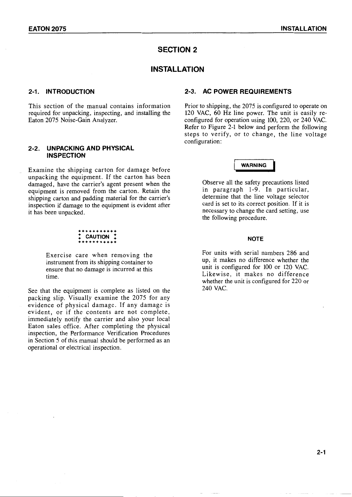
2-1.
INTRODUCTION
This
section
required for unpacking, inspecting, and installing the
Eaton 2075 Noise-Gain Analyzer.
2-2. UNPACKING AND PHYSICAL
INSPECTION
Examine
unpacking the equipment.
damaged, have the carrier's agent present when the
equipment is removed from the carton. Retain the
shipping carton and padding material for the carrier's
inspection
it has been unpacked.
of
the manual contains information
the
shipping
if
damage to the equipment is evident after
carton
If
for
the
damage
carton
before
has been
•••••••••••
! CAUTION !
•••••••••••
Exercise
instrument from its shipping container to
ensure that
time.
See that the equipment is complete as listed on the
packing slip. Visually examine the 2075 for any
evidence
evident,
immediately notify the carrier and also your local
Eaton sales office. After completing the physical
inspection, the Performance Verification Procedures
in
Section 5
operational or electrical inspection.
of
or
care
when
no
damage
physical
if
the
of
this manual should be performed
damage.
contents
removing
is
incurred at this
If
any
are
not
the
damage
complete,
as
an
is
2-3.
Prior
configured for operation using
Refer
steps
configuration:
AC
POWER REQUIREMENTS
to
shipping, the 2075
VAC,
120
60 Hz line power. The unit is easily re-
to
Figure
to
Observe all the safety precautions listed
in
determine that the line voltage selector
card is set to its correct position.
necessary to change the card setting, use
the following procedure .
For units with serial numbers 286 and
up,
unit
Likewise,
whether the unit
240
2-1
verify,
paragraph
it
is
VAC.
or
makes
configured for
below and perform the following
no
it
is
to
change,
WARNING 1
1-9. In
NOTE
difference whether the
makes
is
configured for 220
configured to operate on
100,
220,
or
240
VAC.
the
line
voltage
particular,
If
it is
100
or
120
VAC.
no
difference
or
2-1
INSTALLATION
EATON
2075
1.
On the rear
of
the unit, locate
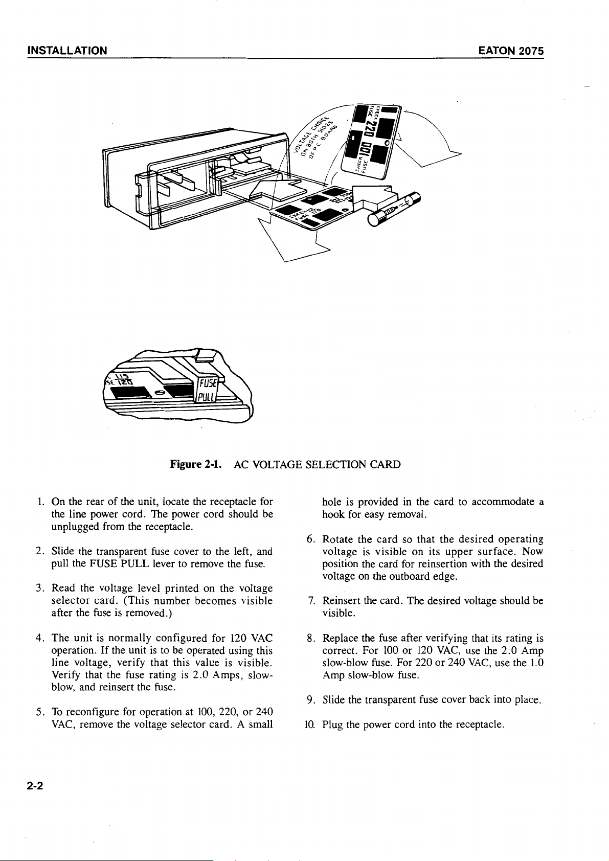
Figure 2-1.
the
AC
VOLTAGE
receptacle for
SELECTION CARD
the line power cord. The power cord should be
unplugged from the receptacle.
6.
2.
Slide the transparent fuse cover
to
the left, and
pull the FUSE PULL lever to remove the fuse.
3. Read the voltage level printed on the voltage
selector card. (This number becomes visible
7.
after the fuse is removed.) visible.
120
4. The unit is normally configured for
operation.
If
the unit
is
to
be operated using this
VAC
8.
line voltage, verify that this value is visible.
Verify that the fuse rating is 2.0 Amps, slowblow, and reinsert the fuse.
9.
5.
To
reconfigure for operation at
VAC,
remove
the
voltage selector card. A small
100,
220, or 240
10.
hole is provided in the card to accommodate a
hook for easy removal.
Rotate the card so that the desired operating
voltage is visible on its upper surface. Now
position the card for reinsertion with the desired
voltage on the outboard edge.
Reinsert
Replace the fuse after verifying that its rating
correct. For
slow-blow fuse. For 220 or 240
the
card. The desired voltage should be
100
or
120
VAC,
use the
VAC,
2.0
use the
is
Amp
1.0
Amp slow-blow fuse.
Slide the transparent fuse cover back into place.
Plug the power cord into the receptacle.
2-2
EATON
2075
INSTALLATION
WARNING 1
The power line cord
to
ensure that the instrument chassis
connected
conditions
interrupted,
tobe
used.
to
the main ground. Under
is this
or
is
a 3 wire assembly
is
no
ground
a 2 wire extension cord
lead
to be
•••••••••••
! CAUTION !
•••••••••••
Observe all the safety precautions given
in
paragraph
2-4. OPERATIONAL INSPECTION
After verifying that the 2075 is configured for the
correct line voltage, the unit should be subjected
Performance Verification Tests in Section 5
manual. After completion
ready for bench-top operation.
1-9.
of
these tests, the unit
to
of
the
this
is
Operation outside this range for extended periods will
result in degradation
eventual malfunction.
2-6. SELECTION
The RELAY POWER connector on the 2075 front
panel provides voltage to automatically energize
external relays during Second Stage Calibration .
This voltage
+
15,
or + 30 volts DC.
the unit
2 and perform the following steps to select + 5 or +
volts
DC.
is
jumper selectable and can be set
is
shipped from the factory. Refer
of
electrical performance and
OF
RELAY
lt
is
DC
VOLTAGE
set
to
+ 30 volts before
to
to
+ 5,
Figure
215
•••••••••••
! CAUTION !
•••••••••••
Observe all the safety precautions given
in paragraph
instrument and
1-9
for protection
of
personnel.
of
the
2-5. OPERATING TEMPERATURE
The 2075 is designed to operate within specified
performance limits over an ambient temperature range
extending from 0
to
55 degrees Centigrade.
2-3
INSTALLATION
Top
Partition
,
,
,
,
,
,
,.
,
,
,
,
,
,
,
,
,
,
,
,
A4
DUEi
BDES
BOARD
. } .
.
.
EATON
2075
view
of
2075
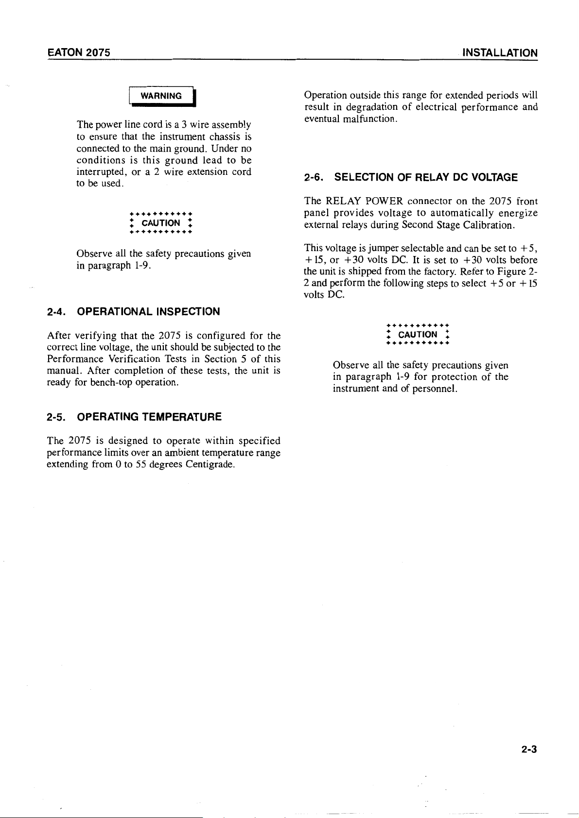
1.
Remove the
on the rear
2. Remove the single 6-32 screw which secures the
top cover panel. Slide the cover to the rear
unit and remove it.
3. Two internal covers are exposed. Remove the Figure 2-2 above. A jumper
nine 4-40 screws which secure the right side pins E3 and E4, selecting
internal cover (the RF Deck Cover) and remove
the cover.
4.
Locate the
Figure 2-2 above.
5. Remove the three board holding screws which
are located along the top edge
AC
of
the 207 5.
A4
board. Its position is shown in jumper between pins E 1 and E2.
A4
Board
front
Figure 2-2. EXTERNAL RELAY
power cord from its receptacle 6. Unplug the connectors located near the top edge
of
the board.
.,,,.
of
,,.""'
the
.,,,.
.,,,.
.,,,.
.,,,.
.,,,.
.,,,.
.,,,.
.,,,.
VOLTAGE
of
be removed.
connector.
Locate
7.
located in the center
8.
To
pins
9.
To
in
SELECTION
the board,
the
select + 5 volts, connect the jumper between
E5
and E6.
reassemble the unit perform steps 1 through 6
reverse.
as
necessary, so that the board can
Lift
the
board
pins
E 1
through
of
the board as shown in
+ 30 volts.
To
select +
free
of
its edge
E6.
These
is
installed between
15
volts, connect the
are
2-4
EATON
2075
INSTALLATION
2-7.
EQUIPMENT MOUNTING
The 2075 comes equipped with four supporting feet
allow bench-top operation. The unit may also be
mounted in a standard
angled support brackets
The rack mounting kit, Option
panel brackets and the necessary screws for attaching
the brackets to the 2075.
The Slide Mount Kit, part number 1-998725, consists
of
the two slide mount assemblies and the required
mounting screws. Both kits are required for mounting
the unit on slides.
brackets, only Option
19
inch equipment rack on
or
on sliding mounts.
11,
For
rack
mounting on angled
11
is required.
consists
of
two front
to
NOTE
The Slide
ordered
purchased. The unit
slide mounts installed.
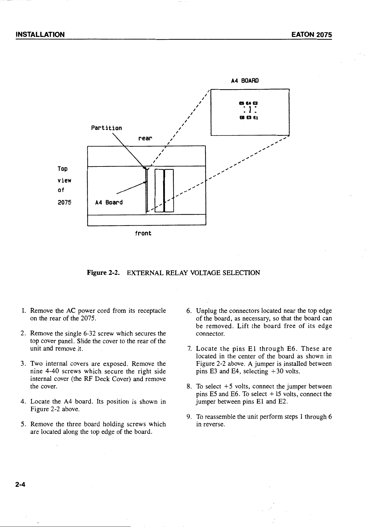
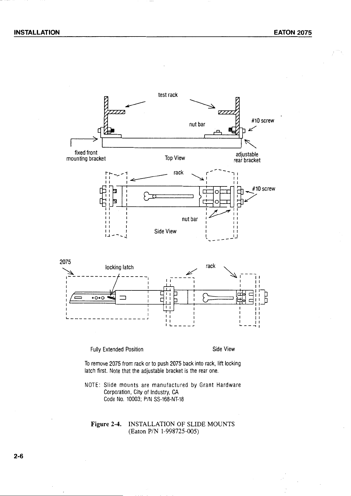
2-8. RACK-MOUNTING THE 2075
Refer to Figure 2-3 to attach the rack mount brackets
to the 2075. Refer to Figure 2-4 for installation
2075
on
slide mounts in a standard equipment rack.
Mount
when the 2075 is
Kit option must be
is
shipped with the
originally
of
the
(bot
not
tarn
shown)
screws
- 2]-
Figure 2-3. INSTALLATION
i----------1
Top
View
OF
RACK MOUNTS
2-5
INSTALLATION
fixed
mounting
front
bracket
test
rack
Top
View
nut
bar
#10
/
adjustable
rear
bracket
screw
EATON
2075
fi---;
II
~
~----=-----1
II
1 1 1 1 1 1
i i i
1 1 1 1 1 1
1 1 1 1 1 1
1 1 1
l.J---..!
~
1 1 1 1
j
_G:x...____i_
1
Side
rack
~
(----;:
~_'
View
nut
"'"---'---'---f
~~~
1~11
bar
i i i
1 1 1
t __
IJ
~~o
screw
"----
rack
2-6
Fully
Extended
To
remove
latch
first.
NOTE:
Slide
Corporation,
Code
Figure 2-4. INSTALLATION OF
2075
Note
No.
Position
from
rack
or
to
push
that
the
adjustable
mounts
are
City
of
10003;
P/N
(Eaton PIN 1-998725-005)
bracket
manufactured
lndustry,
SS-168-NT-18
2075
CA
back
is
the
by
SUDE
into
rear
Grant
rack,
Side
View
lift
locking
one.
Hardware
MOUNTS
EATON
2-9. EQUIPMENT INTERCONNECTIONS
Refer
additional information on the rear panel connectors
discussed
connectors
Z outputs which may be used to display data on
oscilloscope or analog
between
oscilloscope or plotter inputs
utilized. When an oscilloscope is being used to display
data, the !NT (intensity) adjustment on the rear panel
should be adjusted fully clockwise initially, and then
adjusted to obtain the desired difference in intensity
between the noise figure and gain traces. When an
plotter
to the plotter pen-lift input. Refer to paragraph 3-42
for the procedures detailing usage
The IF OUT connector is provided on the rear panel
the 2075 to allow measurement or display
MHz IF signal. This signal is the result of the second
stage
between this BNC-type connector and an appropriate
measurement device,
2075
to
Figure 3-2 and Table 3-2 for the locations and
below. The 2075 has
on
its rear panel. These provide X,
X-Y
Plotter. Install test cables
these
is
being used, the Z output should be connected
of
internal downconversion. Install a test cable
outputs
and
if
desired for test purposes.
three
the
corresponding
if
this function
of
these functions.
BNC-type
is
of
Y,
and
an
to be
X-Y
of
the 30
INSTALLATION
The DET OUT connector
to allow measurement or display
Output voltage. Install a test cable between this BNCtype connector and an appropriate measurement
device if desired for test purposes.
The line power receptacle on the Eaton 2075 rear
is
panel
the line power cord to this receptacle.
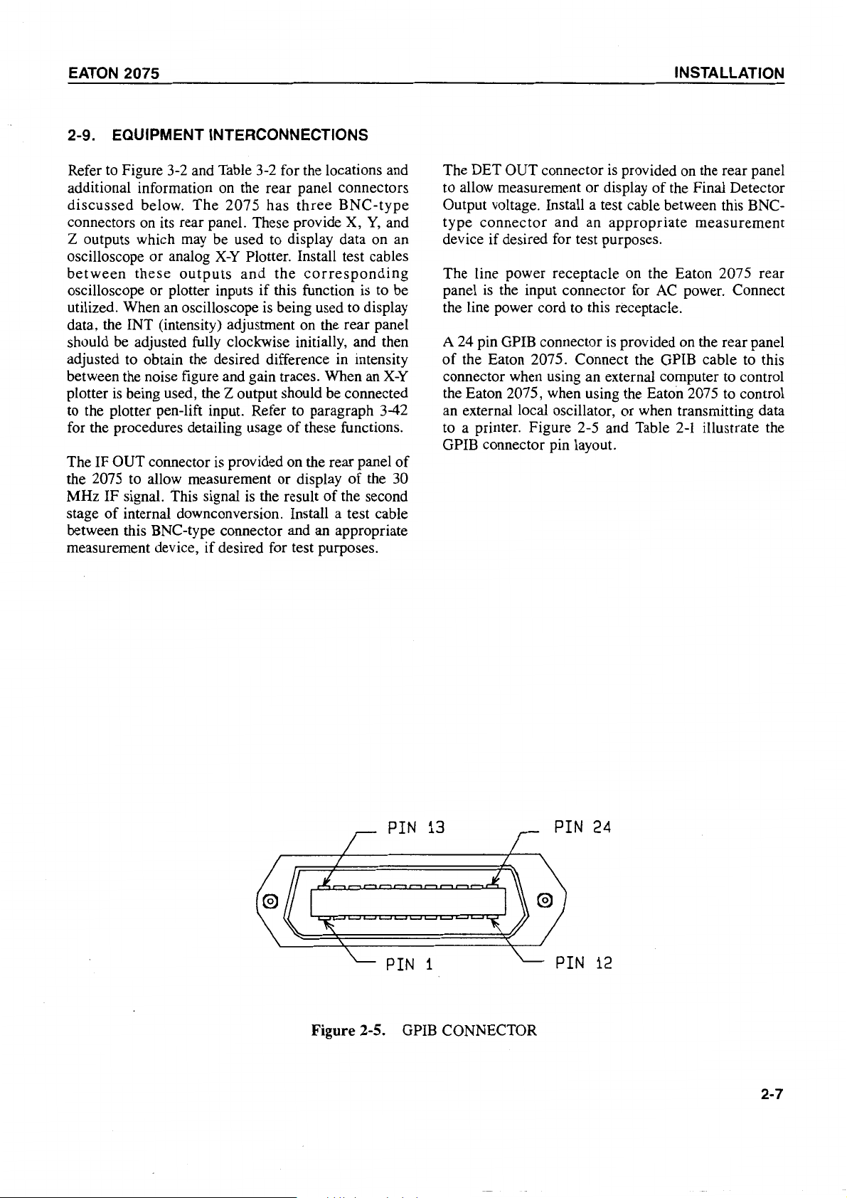
A 24 pin GPIB connector
of
connector when using an external computer to control
the Eaton 2075, when using the Eaton 2075 to control
an external local oscillator, or when transmitting data
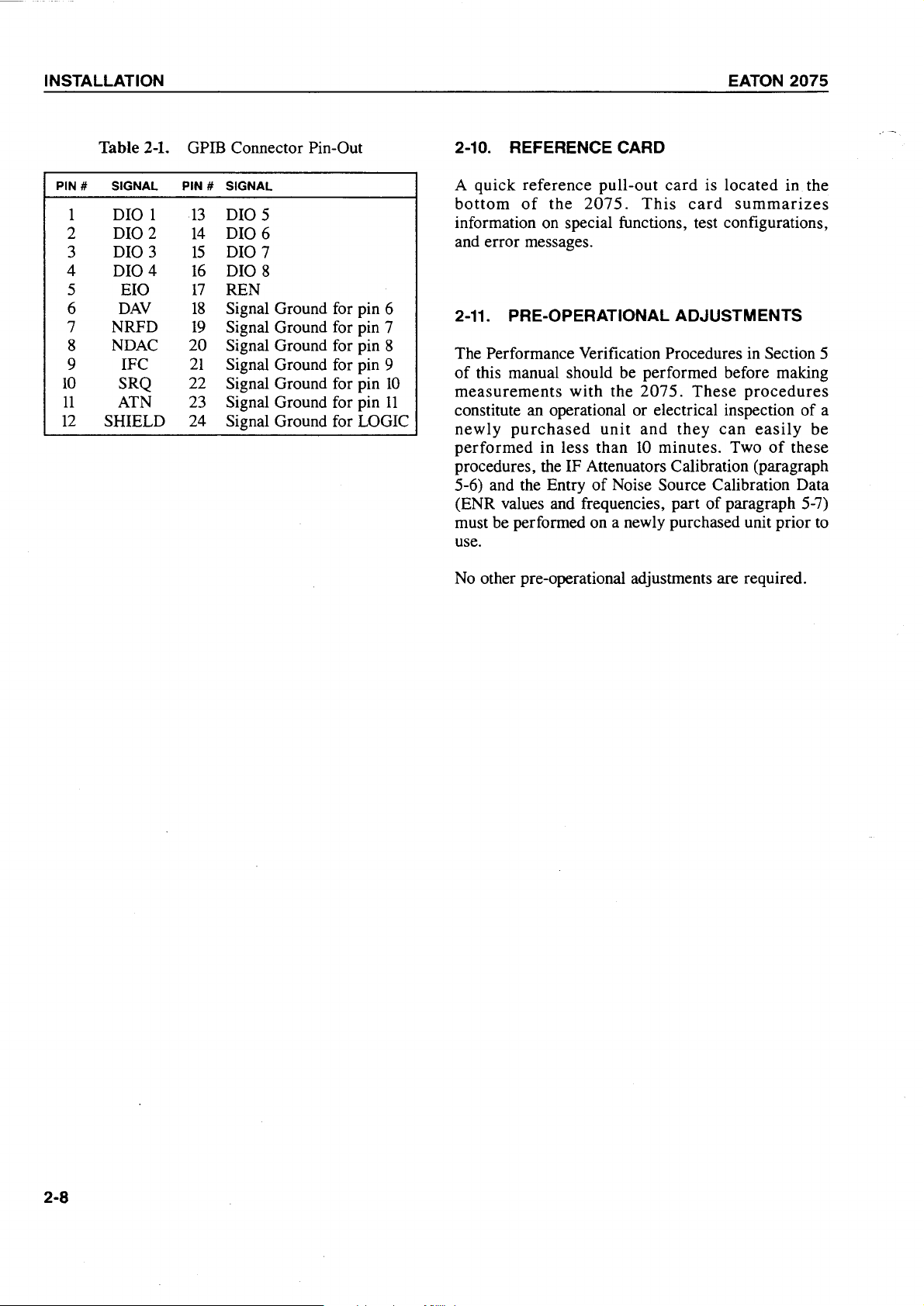
to a printer. Figure 2-5 and Table
GPIB connector pin layout.
the input connector for
the Eaton 2075. Connect the GPIB cable to this
is
provided on the rear panel
of
the Final Detector
AC
power. Connect
is
provided on the rear panel
2-1
illustrate the
PIN
13
PIN
1
Figure 2-5. GPIB CONNECTOR
PIN
PIN
24
12
2-7
INSTALLATION
Table
2-1.
GPIB Connector Pin-Out
2-10. REFERENCE CARD
EATON
2075
PIN # SIGNAL
1 DIO 1
DI02
2
3 DIO 3
0104
4
5
6
EIO
DAV
7 NRFD
NDAC
8
9 IFC
10
11
12
SRQ 22
ATN 23 Signal Ground for pin
SHIELD
PIN
# SIGNAL
DIO 5
13
14
DI06
15
DIO 7
16
DIO 8
17
REN
18
Signal Ground for pin 6
19
Signal Ground for pin 7
20
Signal Ground for pin 8
21
Signal Ground for pin 9
Signal Ground for pin
10
11
24 Signal Ground for LOGIC
A quick reference pull-out
bottom
of
the
2075.
card
This
is located in the
card
summarizes
information on special functions, test configurations,
and error messages.
2-11.
PRE-OPERATIONAL ADJUSTMENTS
The Performance Verification Procedures in Section 5
of
this manual should be performed before making
measurements
with the
207
5.
These
procedures
constitute an operational or electrical inspection of a
newly
performed
procedures, the IF Attenuators
5-6) and the Entry
(ENR values and frequencies, part of paragraph
purchased
in less than
unit
and
they
can
easily
10
minutes. Two
Calibrati~n
of
Noise Source Cahbrat1on Data
of
(p~agraph
be
these
5-7)
must be performed on a newly purchased unit prior to
use.
No other pre-operational adjustments are required.
2-8
EATON
3-1.
2075 OPERATION
INTRODUCTION
SECTION 3
OPERATION
3-2. CAPABILITIES OF THE
EATON
2075
This section
procedures
Noise-Gain Analyzer. The 2075 is microprocessorcontrolled using
extremely wide range
front panel controls have multiple functions. This
section
process
rapidly bring the new user to the process
measurements.
Figure
and indicators together with their functions and the
corresponding keystroke sequences. Figure 3-2 and
Table 3-2 show the rear panel controls and indicators
together with their functions.
After
procedure
Noise
sequences are included in the procedure.
The
2075
configurations. The type
and
its
configuration
contains
measurements in each possible test configuration.
Paragraph
selecting the needed configuration. Table 3-4 also
directs
complete measurement
configuration. Each procedure includes the necessary
steps,
keystroke sequences to perform each function. These
procedures
measurement.
The
paragraphs
procedures give detailed information on the various
subjects relevant to usage
of
the manual contains information and
necessary to operate the Eaton 2075
ROM
resident firmware.
of
capabilities and many
of
the manual is organized to simplify the
of
learning how to operate the 2075, and to
3-1
and Table
inspecting and installing the
of
Ratio)
is used in any
output
is
stand-alone
3-10
the
user
the
control
are
3-1
show the front panel controls
2075,
paragraph 3-9 to enter ENR (Excess
values.
frequencies
required. This section
and Table 3-4 serve as a guide to
to the
basic
following the
All
of
Device Under Test (DUT)
procedures
paragraph
procedure
functions
to
making
of
the 2075.
necessary
of
six
different
determine
of
containing
for the needed
used,
and
any
test
configuration
keystroke
which
the manual
for
automatic
lt
has an
of
of
making
use the
making
the
exact
the
test
test
the
The 2075 is fully compatible with the
General
instrument may be operated in any
LISTENER/TALKER, TALK
CONTROLLER.
In LISTENER/TALKER mode, an external controller
controls the 2075 via an IEEE-488 GPIB. When the
instrument is powered-up, it assumes this mode and
immediately addressable by the external controller.
See Section 4
The TALK ONLY (TALK
send measurement data to a GPIB compatible printer
or
other listener device. In this mode no external
controller
accomplished via the front panel.
The LIMITED CONTROLLER mode is the mode
wherein the 2075 controls the frequency and power
a GPIB compatible, external signal source which
used
several ROM resident programs to control different
models
write and enter a custom program via the front panel.
No
external controller
all control
front panel.
In any mode, the 2075 can drive an oscilloscope,
plotter, or strip chart recorder to display results
gain or noise measurements. For more information see
paragraph 3-42, page 3-89.
The input frequency range
MHz
configuration, measurements can be made for devices
having output frequencies in this range. Through use
of
one
measurements can also be made at RF frequencies
to 65.535 GHz (test configurations 2 through 6).
Sideband parameters are
measurements to be made single upper sideband,
single lower sideband,
Purpose
of
is used
as
a local oscillator. The 207 5 can use one
of
signal sources.
of
the 2075
to 1850
or
two stages
Interface
this manual.
ALWAYS)
and
all
lt
is
used while in this mode and
is
accomplished through the
of
MHz.
In
of
external downconversion,
user
or
double sideband.
Bus
ONLY,
control
also allows the user
the 2075 extends from
the
most
selectable allowing
IEEE-488
(GPIB).
of
three modes:
and LIMITED
mode is used to
of
the
basic
The
2075
X-Y
test
up
is
is
of
is
of
to
of
10
3-1
OPERATION
The
2075
can
make
FIXED
FREQUENCY
SWEPT FREQUENCY measurements.
or
EATON
2075
subtracted. A Second Stage Calibration must be
performed before making a corrected measurement.
FIXED
power-on, and it
are made at a single frequency. Before and
measurements,
FREQUENCY
is
the mode in which measurements
manual
is the default mode
frequency
increment/
after
after
decrement keys can be used to tune the frequency up
or down
paragraph 3-6, page
In
in
SWEPT
steps. The step size is user selectable. See
3-21.
FREQUENCY
mode,
START
FRE-
QUENCY, STOP FREQUENCY, and SWEPT FRE-
by
QUENCY STEP SIZE are entered
the user. The
maximum number of measurement points in this mode
is
equal to the frequency range width in MHz, divided
by
the maximum frequency resolution. For example,
if
the measurement range extends from
MHz,
1850
dividing
of
.1
MHz, gives 18,400 measurement points. See
paragraph
Swept frequency mode is selected
1840
3-7,
giving a
by
range
width
the maximum frequency resolution
page 3-22.
by
10
MHz to
of
1840
MHz,
initiating either a
SINGLE SWEEP or CONTINUOUS AUTOMATIC
SWEEPS.
SECOND STAGE CALIBRATION is the procedure
of
wherein the 2075 measures the noise figure
the
entire measurement system, excluding the Device
Under Test (DUT). The calibration data obtained is
by
used
Stage) measurements
STAGE CALIBRATION the 2075 can store up to
the instrument when making corrected (First
of
the DUT. During SECOND
100
calibration points. The number of calibration points
and
their
measurement frequency parameters entered
frequencies
are
determined
by
by
the
the
user. Seeparagraph 3-34, page 3-75.
The
2075
measurements
can
make
or
corrected
uncorrected
(first
(cascade)
stage)
mea-
surements. A cascade measurement gives a single
of
value which includes the noise
Test (the first stage) combined with the noise
measurement system (the second stage).
is
Stage Calibration
necessary before making cascade
the Device Under
of
the
No
Second
measurements.
A corrected, or first stage measurement, is essentially
cascade
a
contribution
measurement
of
the measurement system has been
from
which
the
noise
After
measurement mode
power-up,
the
2075
by
default. Performing the Second
is in
the
cascade
Stage Calibration automatically places the instrument
into the corrected measurement mode.
of
Three ENR tables allow the storage
up
ENR values for
to 3 different noise sources. Each
table can store the ENR data for up to
Frequency/
31
frequencies.
A fourth table stores a single ENR value which can be
used for all frequencies. A fifth table can be provided
by
an
optional PROM chip which contains frequency
ENR
and
values for a specific noise source. See
paragraph 3-9, page 3-26, and paragraph 3-30, page
3-71.
The
2075
can
make
the
following
automatic
measurements:
Noise Figure
(F)
(Cascade only)
Noise Figure and
Gain (or Loss)
(F+G)
(Corrected only)
Eff ective Input Noise
Temperature
(Te)
(Cascade or
corrected)
Y-Factor
(Y)
(Cascade only)
Operating Noise
Temperature
(Top)
(Cascade or
corrected)
Power
(dB)
(Cascade or
corrected)*
Excess Noise Ratio
(ENR)
(Cascade or
corrected)*
Noise Measure
*Cascade
measurements
are
(M)
not
(Corrected only)
recommended
for
these.
The following measurements can be made manually:
Corrected Noise
Figure and Gain
+G)
(or Loss) (F
See Paragraph 3-27,
page 3-67.
Cascade Noise Figure (F) See Paragraph 3-27,
3-67.
page
Y-Factor (Y) See Paragraph 3-28,
page 3-69.
3-2
EATON
2075
OPERATION
The 2075 can store its front panel control parameters
of
for later retrieval and reuse. Nine sets
parameters can be stored and then sequentially
control
or
randomly retrieved. The retrieval sequence is user
programmable. Seeparagraph 3-48, page
A number
subordinate
of
special functions, each with multiple
functions,
extend
the
instrument's available features beyond those
3-110.
range
of
of
the
the
dedicated front panel controls. See paragraph 3-46,
page
3-101.
The 2075 displays error messages in the event
procedural
page
Loss
2075 compensates for known losses
or
hardware error. See paragraph 3-4
3-106.
or
gain compensation
is
available wherein the
or
of
7,
gains that
cannot be included in Second Stage Calibration. See
paragraph 3-40, page 3-86.
Laboratory
accuracy
compensation
temperature
ambient
of
noise measurements. The 2075 allows
of
the noise source and thereby increases
temperatures
for
variations
can
in the
affect
cold
or
the
off
measurement accuracy. See Tcold Compensation,
paragraph
The
measurement
3-41,
bandwidth
system,
page 3-88.
of
the
can
DUT,
be a
relative
factor
to
the
affecting
measurement accuracy. The 2075 provides a method
of
compensating for bandwidth differences when the
of
bandwidth
bandwidth
the DUT is less than the measurement
of
the 2075. See Bandwidth Compensation,
Paragraph 3-38, page 3-82.
3-3. CONTROLS AND INDICATORS
The controls and indicators, and their functions, are
listed
in
Table
3-1.
Because the 2075 offers such a wide range
functions, a single key may initiate two
functions. The primary function
indicated
by
the
key
example, the key START
display
measurement.
initiated by pressing that key once.
a
or
entry
of
The
label
FREQ
the start frequency for a swept
primary
of
such a key is
or
designation.
is used to allow
function
Where a key has a secondary function, this function
indicated
key.
For
by
the orange lettering above or beside the
example,
the key
START
secondary function which allows display or entry
IF frequency from an external mixer. Accordingly, the
orange designation,
key. The secondary,
initiated
by
pressing the orange
then the function
the IF frequency, press
FREQ.
IF,
is
located just to the left
or
shift
function
SHIFT
key.
For example, to enter
SHIFT
and then START
In addition to the primary and secondary functions,
some keys have a
function
of a key
operation. While
tertiary
is
specific
in
that particular mode, pressing the
function. The
to
a particular mode of
function key initiates the tertiary function.
The
2075 front
panel
is
designed
so that
multiple keystrokes are required, the sequence
left to right.
of
available
or
of
a key is
FREQ
of
a key is
key
first, and
or
tertiary
more
For
is
has a
of
an
of
the
display
where
is
from
The allowable external gain
dB.
Because this parameter
of
the DUT
is
bandwidth dependent,
is
normally 50
allowable external gain can be increased to as much as
70
dB.
Seeparagraph 3-35, page
3-77.
The keys
of
the numeric keypad are used for entry of
numeric values. In all cases, the numeric entry is
completed
Table
by
pressing the ENTER
3-1
lists the controls and indicators together with
key.
primary, secondary, and tertiary functions. The exact
keystroke sequence for each function is also shown.
Wherever functions
or
procedures are discussed in
this inanual, the applicable keystroke sequences are
also included therein.
3-3

 Loading...