

Eaton Cooper Power Series, 200 A 35 kV class Installation Instruction
Loadbreak
COOPER POWER
SERIES
Connectors
CA650087EN
Effective November 2015
Supersedes TD6500 01EN August 2014
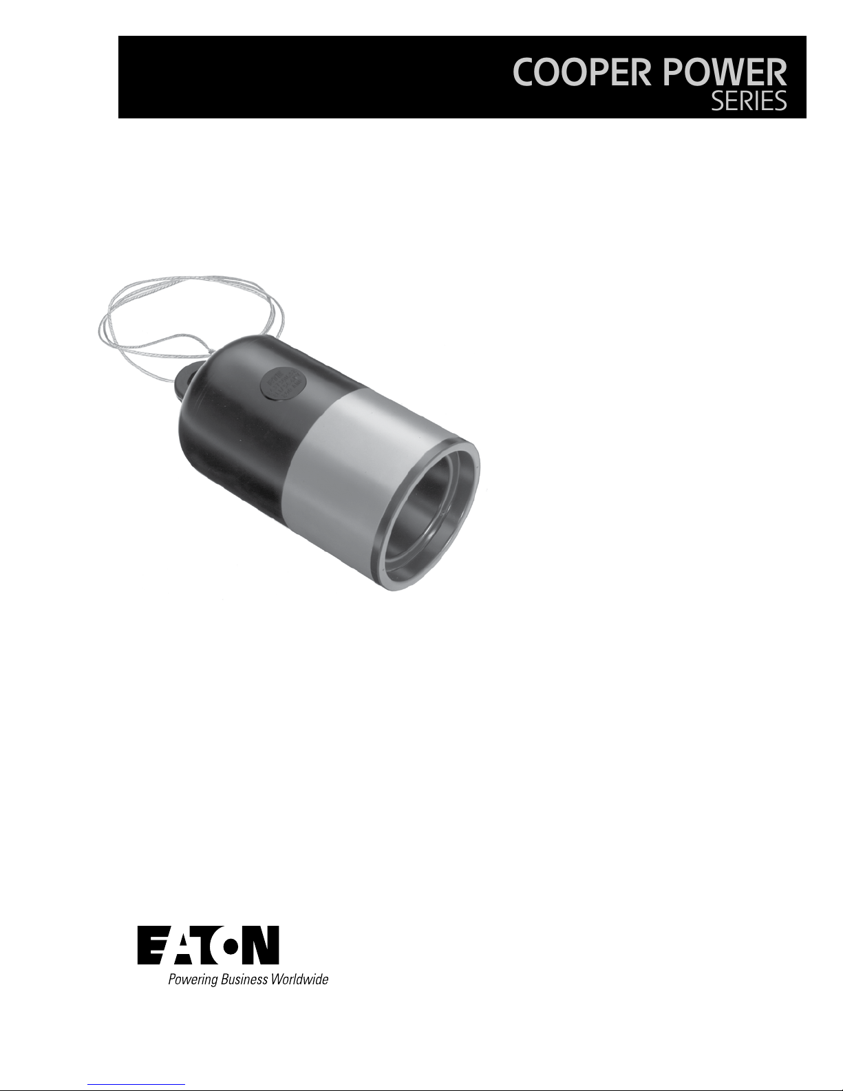
200 A 35 kV class insulated protective
cap
General
Eaton’s Cooper Power™ series 200 A, 35
kV insulated protective cap meets the full
requirements of IEEE Std 386™-2006 standard–
Separable Insulated Connector Systems, and
provides an insulated, fully shielded submersible
cover for an energized 35 kV Class loadbreak
interface. The molded peroxide-cured EPDM
semi-conductive shield maintains ground potential
on the cap’s surface when the drain wire is
attached to a grounding lug. The protective cap is
required for temporary or permanent installation
on 21.1 kV and 21.1/36.6 kV loadbreak bushings,
portable feedthru junctions, and other accessories
having interfaces that conform to IEEE Std 386™2006 standard (200 A loadbreak interface No. 1,
21.1 kV and 21.1/36.6 kV).
Installation
No special tools are required. A clampstick tool is
used to place the protective cap on an exposed
bushing. Refer to Installation Instruction Sheet
S500-65-1 for details.
Production tests
Tests conducted in accordance with IEEE Std
386™-2006 standard.
•
AC 60 Hz 1 Minute Withstand
• 50 kV
•
Minimum Corona Voltage Level
• 26 kV
Tests conducted in accordance with Eaton
requirements.
•
Physical Inspection
•
Periodic Dissection
•
Periodic X-ray Analysis
Catalog Data CA650087EN
Effective November 2015
200 A 35 kV insulated protective cap
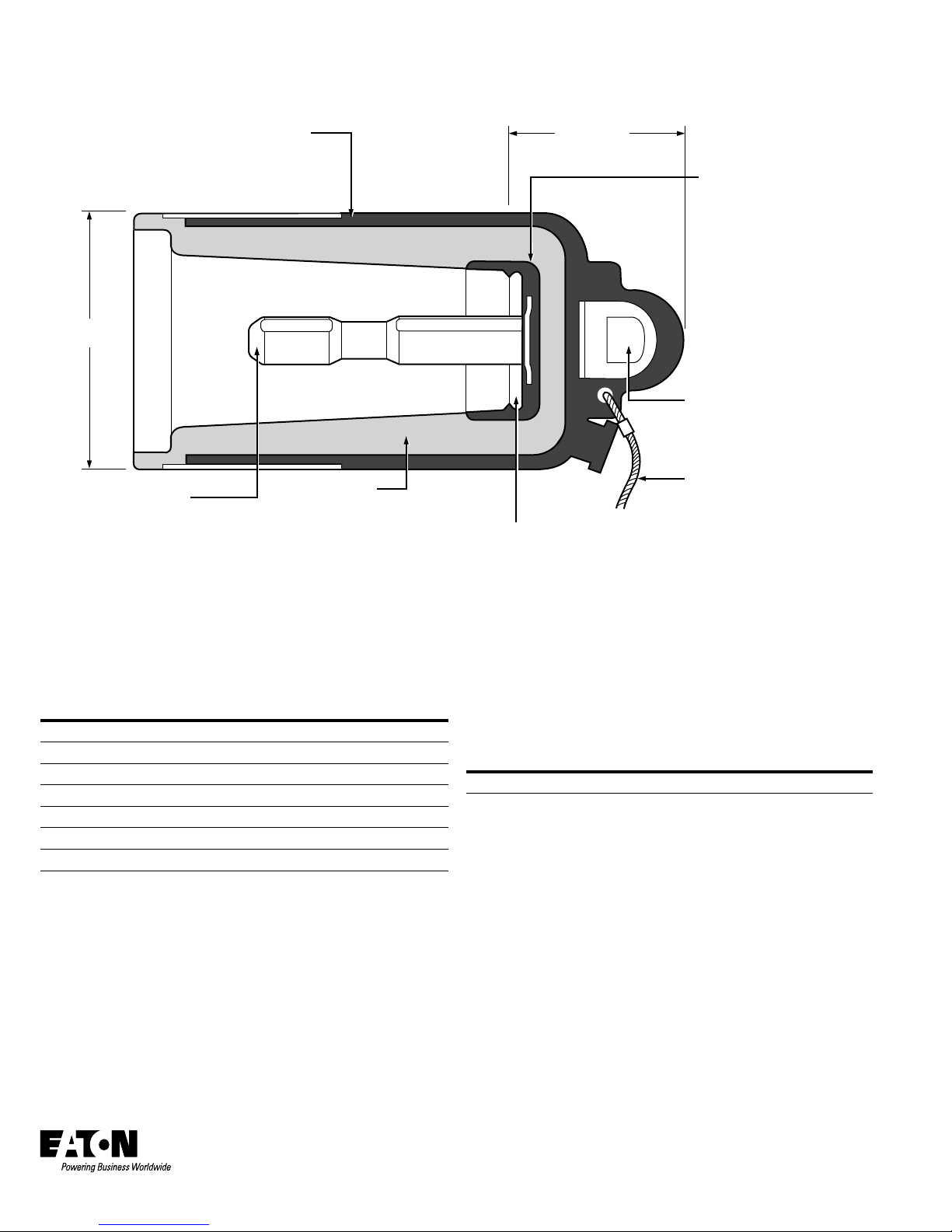
SEMI-CONDUCTIVE SHIELD
Molded Semi-Conductive
Peroxide Cured EPDM
Shield meets requirements of
IEEE Std 592™-2007 standard.
4.0”
(102 mm)
BRASS PROBE
Brass Probe provides reliable
conductive path with mating
female contacts.
EPDM INSULATION
High Quality Peroxide Cured
EPDM Insulation is mixed
and formulated in-house
for complete control of raw
rubber characteristics.
LOCKING RING
Semi-Conductive Molded
Locking Ring locks cap onto
nose piece of mating interface
and provides stress relief.
Figure 1. Cutaway drawing shows design integrity and stacking dimensions.
S3
2.66”
(67.5mm)
FARADAY CAGE
Semi-Conductive Insert, molded
out of Peroxide Cured EPDM
Rubber, equalizes and relieves
voltage stresses created around
probe base.
PULLING EYE
Stainless Steel Reinforced
Pulling Eye ensures high
strength for clampstick operation.
DRAIN WIRE AND
GROUNDING EYE
48-inch, #14 AWG Stranded
Copper Drain Wire ensures
deadfront construction and
avoids low energy discharge
from the molded semiconductive shield. Tin plating
helps prevent corrosion of
drain wire.
ote:N Dimensions given are for references only
Table 1. Voltage Ratings and Characteristics
Description kV
Standard Voltage Class 35
Maximum Rating Phase‑to‑Phase 36.6
Maximum Rating Phase‑to‑Ground 21.1
AC 60 Hz 1 Minute Withstand 50
DC 15 Minute Withstand 103
BIL and Full Wave Crest 150
Minimum Corona Voltage Level 26
Voltage ratings and characteristcs are in accordance with IEEE Std 386™-2006
standard.
Eaton
1000 Eaton Boulevard
Cleveland, OH 44122
United States
Eaton.com
Eaton’s Cooper Power Systems Division
2300 Badger Drive
Waukesha, WI 53188
United States
Eaton.com/cooperpowerseries
© 2015 Eaton
All Rights Reserved
Printed in USA
Publication No. CA650087EN
Ordering information
To order the 35 kV Insulated Protective Cap Kit, refer to Table 2.
Table 2. Protective Cap Kit
Description Catalog Number
Protective Cap LPC235
For a Protective Cap Kit individually packaged in a corrugated cardboard box, insert
an “X” as the last character in the part number. Example: LPC235X.
Each kit contains:
•
Protective Cap with Copper Drain Wire
•
Silicone Lubricant
•
Installation Instruction Sheet
Eaton is a registered trademark.
All other trademarks are property
of their respective owners.
For Eaton's Cooper Power series product
information call 1-877-277-4636 or visit:
www.eaton.com/cooperpowerseries.
 Loading...