

Eaton 145406, 145407, Airflex qrv 9100, 146506, 145141 Installation, Operation And Maintenance Manual
QRV 9100
Installation, Operation
and Maintenance of
Forward this manual to the person responsible
for Installation, Operation and Maintenance of
the product described herein. Without access to
this information, faulty Installation, Operation or
Maintenance may result in personal injury or
equipment damage.
Airflex
Quick Release
Valve
Note: This manual pertains to the AIRFLEX
DIAPHRAGM OPERATED QUICK RELEASE
VAVLE which is identified by its silver housing. If
your valve housing is anodized green, service it
according to manual QRV 9090 or replace the entire
valve with the diaphragm style.
®
Use Only Genuine Airflex® Replacement Parts.
The Airfiex Division of Eaton Corporation recommends
the use of genuine Airfiex replacement parts. The use of
non-genuine Airflex replacement parts could result in
substandard product performance, and may void your
Eaton warranty. For optimum performance, contact
Airflex:
In the U.S.A. and Canada:(800) 233-5926
Outside the U.S.A. & Canada: (216) 281-2211
Internet: www.airflex.com
October, 1987
(Revised : November, 2006)
203977
©Copyright Eaton Corp., 2006. All rights reserved.
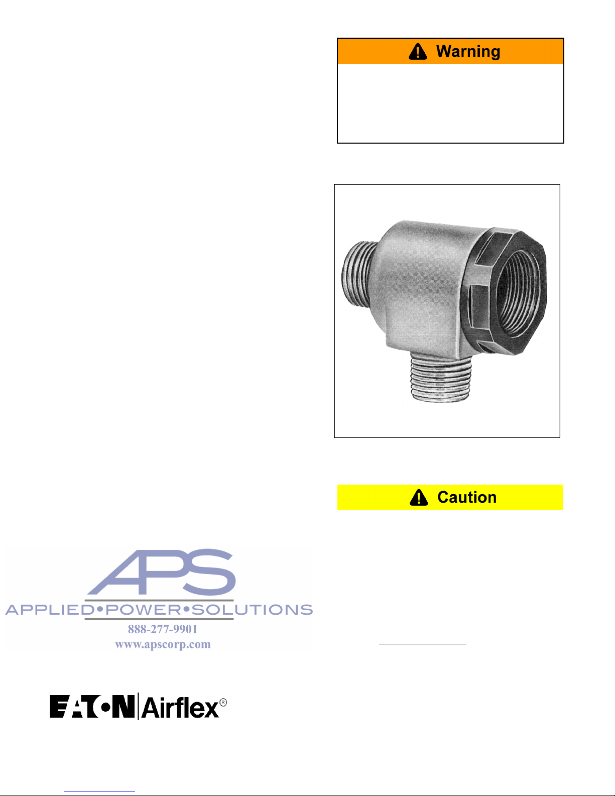
AIRFLEX® QUICK RELEASE VALVE
Figure 1 : Quick Release Valve
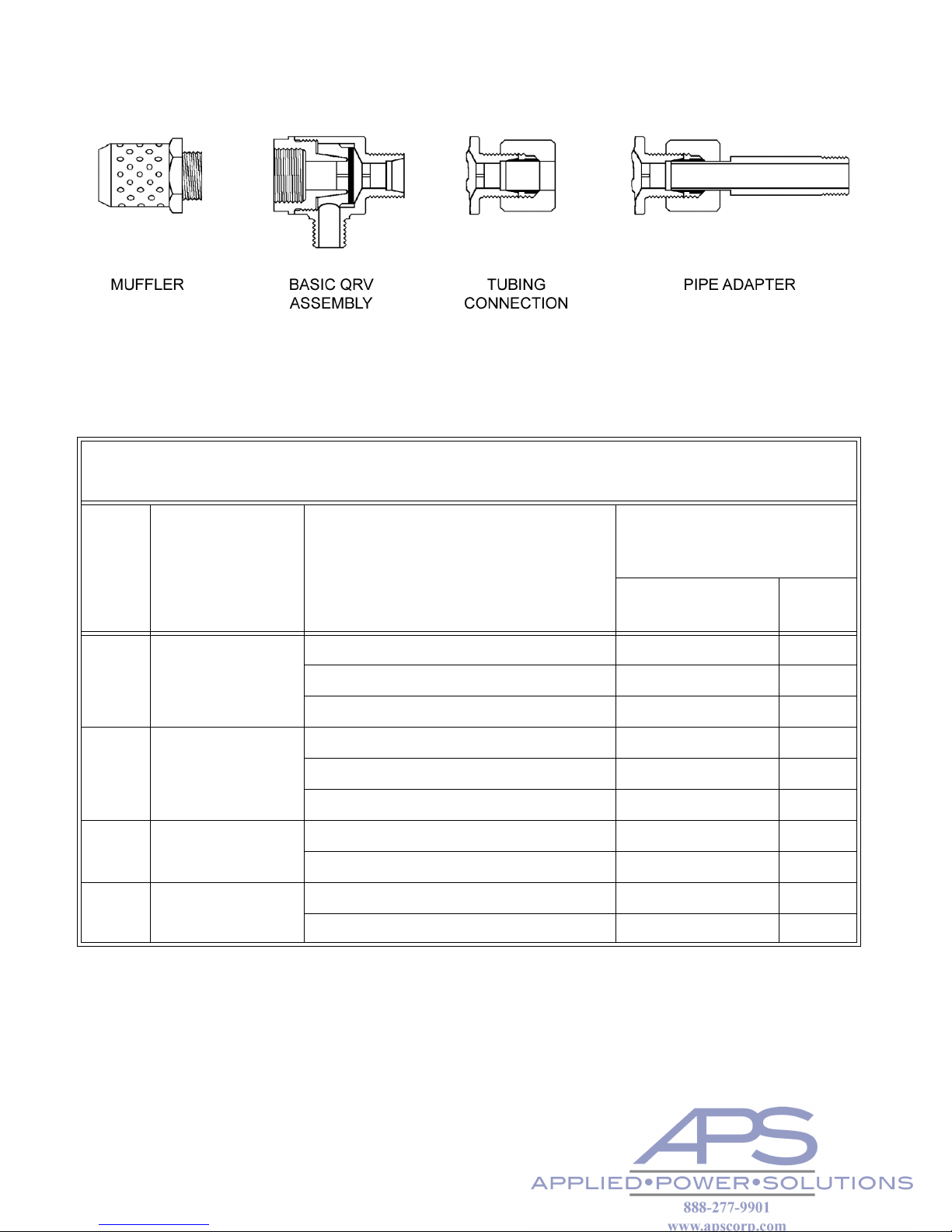
TABLE 1:
QRV MODEL and KIT NUMBERS
QRV
SIZE
BASIC QRV
MODEL and KIT
NUMBER
3/8 145406
1/2 145407
3/4 145141
1” 146506
QRV OPTIONS and KITS
OPTION and KIT
DESIGNATION***
3/8", 1/2" and 3/4" Size 1"
w/Metal Sleeve DE BD
w/Rubber Sleeve DF
w/Inlet Pipe Thread DG
w/Metal Sleeve & Muffler** DS BE
w/Rubber Sleeve & Muffler** DR
w/Inlet Pipe Thread & Muffler** DT
w/Metal Sleeve & Pipe Adapter DL BR
w/Metal Sleeve & 1/4 Pipe Adapter* DM
Diaphragm & End Cap Kit DP DP
Diaphragm, Muffler & End Cap Kit DQ DQ
1/4 NPT adapter for 3/8 QRV only.
*
** Mufflers are not factory-assembled to QRV. See Installation section.
***
The option and kit designation letters must be added as a suffix to the basic model number to completely
identify the QRV model or kit. Diaphragm and end cap kit contains a diaphragm, end cap and sealant. Diaphragm, muffler and end cap kit contains diaphragm, end cap, muffler and sealant.
QRV 9100 (PDF FORMAT) 1
1.0 INTRODUCTION
1.1 Description
Throughout this manual there are a number of
HAZARD WARNINGS that must be read and
adhered to in order to prevent possible personal
injury and/or damage to equipment. Three signal words “DANGER”, “WARNING” and
“CAUTION” are used to indicate the severity of
a hazard, and are preceded by the safety alert
symbol
Denotes the most serious hazard, and is
used when serious injury or death WILL
result from misuse or failure to follow specific instructions.
Used when serious injury or death MAY
result from misuse or failure to follow specific instructions.
The Airflex® QRV is a quick release valve that
facilitates the release of air from a pressurized
chamber i.e., air cylinders, clutches, brakes or
other pneumatic devices. In essence it provides
an exhaust port at the chamber rather than
exhausting through long supply lines and control components. The function they perform is
especially important in high speed cycling
equipment. They prevent sluggish operation,
overlap and excessive wear. Their importance
in an air control system cannot be overemphasized.
QRV’s are available in four sizes for direct connection to 3/8, 1/2, 3/4 and 1 inch pipe. Models
are also available which permit 1/2, 5/8 and 3/4
inch outside diameter tubing connections to the
QRV inlet port.
Exhaust noise from the valve can be reduced
by using a muffler, which threads into the
tapped hole in the end cap.
1.2 How It Works
Used when injury or product/equipment
damage may result from misuse or failure to
follow specific instructions.
It is the responsibility and duty of all personnel
involved in the installation, operation and maintenance of the equipment on which this device
is used to fully understand the:
procedures by which hazards can be avoided.
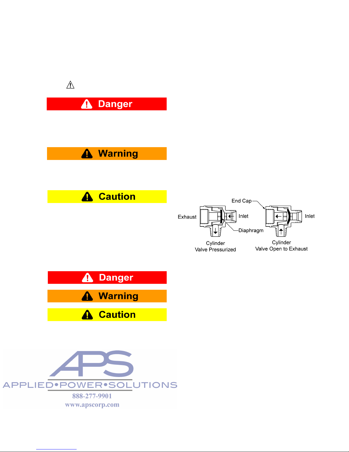
Figure 2
The Airflex QRV contains a diaphragm
designed to function on a pressure differential.
Air pressure at the valve inlet seats the diaphragm on the end cap, closing the exhaust
port. Applied pressure, acting on the outer
unsupported diaphragm area, deflects it and
allows air to flow to the cylinder port. See Fig-
ure 2.
When a pressure drop occurs in the air supply,
the pressure differential lifts the diaphragm from
the exhaust port and seats it on the inlet port.
Air from the pressurized device can now flow
freely to atmosphere through the valve’s
exhaust port.
If the cylinder pressure falls below the inlet
pressure, the pressure differential on the diaphragm will close the exhaust port, preventing
further exhaust.
QRV 9100 (PDF FORMAT) 2 © Copyright Eaton Corp. 2006, All Rights reserved.
 Loading...