

Eaton 12-110-1250y, 12-110-1250-Bxy, 12-110-1500y, 12-110-1800y, 12-110-1800-Bxy Operation And Installation Manual
...
True Sine Wave Inverter
Eaton 1250W / 1500W / 1800W
Inverter Operation and Installation Guide

DISCLAIMER OF WARRANTIES AND LIMITATION OF LIABILITY
The information, recommendations, descriptions and safety notations in this document are based on Eaton Corporation’s
(“Eaton”) experience and judgment and may not cover all contingencies. If further information is required, an Eaton sales
office should be consulted. Sale of the product shown in this literature is subject to the terms and conditions outlined in
appropriate Eaton selling policies or other contractual agreement between Eaton and the purchaser.
THERE ARE NO UNDERSTANDINGS, AGREEMENTS, WARRANTIES, EXPRESSED OR IMPLIED, INCLUDING WARRANTIES
OF FITNESS FOR A PARTICULAR PURPOSE OR MERCHANTABILITY, OTHER THAN THOSE SPECIFICALLY SET OUT IN ANY
EXISTING CONTRACT BETWEEN THE PARTIES. ANY SUCH CONTRACT STATES THE ENTIRE OBLIGATION OF EATON. THE
CONTENTS OF THIS DOCUMENT SHALL NOT BECOME PART OF OR MODIFY ANY CONTRACT BETWEEN THE PARTIES.
In no event will Eaton be responsible to the purchaser or user in contract, in tort (including negligence), strict liability or otherwise for any special, indirect, incidental or consequential damage or loss whatsoever, including but not limited to damage or
loss of use of equipment, plant or power system, cost of capital, loss of power, additional expenses in the use of existing
power facilities, or claims against the purchaser or user by its customers resulting from the use of the information, recommendations and descriptions contained herein. The information contained in this manual is subject to change without notice.
FCC Part 15, Class B
This equipment has been tested and found to comply with the limits for a Class B digital device, pursuant to part 15 of the
FCC Rules. These limits are designed to provide reasonable protection against harmful interference in a residential installation. This equipment generates, uses and can radiate radio frequency energy and, if not installed and used in accordance
with the instructions, may cause harmful interference to radio communications. However, there is no guarantee that interference will not occur in a particular installation. If this equipment does cause harmful interference to radio or television reception, which can be determined by turning the equipment off and on, the user is encouraged to try to correct the interference
by one or more of the following measures:
• Reorient or relocate the receiving antenna.
• Increase the separation between the equipment and receiver.
• Connect the equipment into an outlet on a circuit different from that to which the receiver is connected.
• Consult the dealer or an experienced radio/TV technician for help.
Modifications not expressly approved by the manufacturer could void the user’s authority to operate the equipment under
FCC rules.
ii
Eaton 1250W / 1500W / 1800W Inverter Operation and Installation Guide IM SP180164 / Rev D www.eaton.com

Contents
CONFIGURATION, TROUBLESHOOTING AND SPECIFICATIONS
Introduction ....................................................................................1
Configuration. ..................................................................................2
Inverter display panel .....................................................................2
Customizing default display ................................................................2
Setting battery type and charge current .......................................................3
Fault codes and troubleshooting ....................................................................6
Troubleshooting .................................................................................8
Charger and AC transfer ..........................................................................9
Specifications .................................................................................10
INSTALLATION
Installation types and definitions ........................................15
Choose a location for inverter mounting ...................................17
Mount the inverter. . . . . . . . . . . . . . . . . . . . . . . . . . . . . . . . . . . . . . . . . . . . . . . . . . . .18
Connect the AC input wires (optional for AC input) ..........................19
Connecting AC output wires (optional for hardwire AC output) .................21
Connecting DC input wires .............................................23
Removable display remote mounting .....................................25
Test installation ......................................................26
True Sine Wave Inverter
Eaton 1250W / 1500W / 1800W Inverter Operation and Installation Guide IM SP180164 /Rev D www.eaton.com
iii
True Sine Wave Inverter
Important safety instructions
WARNING
Limitations on use - The Eaton Inverter is not to be
connected to life support devices.
WARNING
Explosion hazard - Working with batteries can be very
dangerous. It is crucial to follow all steps completely
while servicing the unit. It is possible for the inverter to
produce arcs and/or sparks, do not install or use inverter
near flammable materials (i.e. gas- powered machines,
fuel tanks, or any components connected to a fuel supply).
Follow any instructions from the battery manufacturer being
used.
CAUTION
Risk of injury - To avoid risk of injury, use only 12Vdc, lead-
acid, rechargeable batteries (i.e. GEL, AGM, and Flooded).
Other types of batteries may burst, resulting in personal
injury and/or damage.
IMPORTANT
Do not cover/obstruct ventilation systems.
•
Use wire in good condition and of appropriate ratings.
•
Attachments not recommended by Eaton may be
•
damaging to inverter.
Do not use inverter after being dropped, hit, or
•
damaged.
Do not disassemble the inverter. Risk of shock, fire,
•
and void of warranty may result.
Remove all AC and DC connections before
•
maintenance, cleaning, or circuit work.
Provide inverter an equipment-grounding conductor
•
connected to AC input ground.
Insure cables are routed properly, secured and
•
protected from chaffing.
WARNING
Failure to follow these instructions could result in death,
personal injury or property damage.
Personal precautions when working with
batteries
WARNING
Risk of electrical shock, burn from high short-circuit
current, fire or explosion from vented gases.
• Follow the instructions and precautions from the
battery manufacturer (i.e. cap removal, or charging
rates).
• Follow battery instructions for water and battery acid
levels from the battery manufacturer.
• Ventilate the area near the batteries as much as
possible.
• Do not smoke or produce flame/spark near engine or
batteries.
• Use caution when handling tools around batteries.
• Remove all metal items (i.e. rings, bracelets, watches)
from person when working with batteries.
• Work within voice range of other people.
• Wear eye and clothing protection while working, and
avoid touching eyes during installation.
• Upon battery acid contacting skin or clothing, wash
immediately with soap and water.
• Upon contacting eye(s), flood immediately with running
cold water for at least twenty minutes and seek
medical attention.
CAUTION
DC connection precaution(s) - Make only DC output
connections or disconnections after setting all unit switches
to OFF position and opening AC disconnect(s).
CAUTION
Hard wired AC output connection caution - Always use
an external GFCI with hard wired AC output. WARNING:
Risk of electrical shock. Use only 20A rated GFCI receptacle
with UL listing.
NOTES
It is recommended to review TMC RP 160 and RP 163,
which include wiring and selection recommendations.
iv
Eaton 1250W / 1500W / 1800W Inverter Operation and Installation Guide IM SP180164 /Rev D www.eaton.com

Introduction
Introduction
The Eaton Inverter is designed to create 1.8kW of pure sine wave 115VAC 60Hz power from a 12V battery source. The units
low THD (<2.5% typical) can power sophisticated electronics that may not work with modified sine wave inverters. Unit also
has high surge capability to power up hard to start loads like power tools, refrigerators or pumps.
The Eaton Inverter is protected against most abnormal conditions found in the automotive environment.
The unit has an under voltage alarm and shut down that prevents the batteries from becoming depleted.
A warning alarm will sound when the maximum power output is being reached. An alarm will also sound if unit is
overheating. If any of these conditions are not corrected, the unit will turn off safely to protect itself.
Some models include a three stage temperature compensated battery charger that maximizes the life of the batteries. It can
be configured for AGM, flooded or Gel lead acid batteries.
Eaton inverters include a Shore Power bypass feature. When AC power (Shore Power) is detected at the AC input, the unit
powers all accessories from this available power source. If the inverter automatically detects that AC input is removed, it
becomes an independent AC supply.
Inverter input current could be as high as 200A in the 1.8KW unit. Special care has to go into evaluating the proper sizing of
batteries, wire gauge and length.
The inverter’s logic is powered by the 12V input battery. The unit current draw when power is off is typically less than 2mA.
When the inverter is turned on with no load connected to its output it will typically draw less than 0.5A.
Operation efficiency is input voltage, load and ambient temperature dependent, but it is typically 90%.
The Eaton inverter will not withstand reverse polarity. Permanent damage will occur and is not covered by warranty.
Eaton 1250W / 1500W / 1800W Inverter Operation and Installation Guide IM SP180164 / Rev D www.eaton.com
1
Configuration guide
Configuration guide
This chapter describes inverter operation, configuration and the meaining of error codes.
Setting battery types on main unit (models with battery charger only)
The inverter can operate from and recharge several different types of lead-acid batteries. It is important to make sure the battery type is configured on the unit for optimum charging process before installing batteries. See Table 1.
Customizing display, alarm and charging current settings
The display panel is capable of adjusting the following:
• What is presently displayed on the screen
• Modify the charging current
• Enable/Disable the inverter output
• Enable/Disable the audible alarm
• Modifying the shutdown voltage value
• Select battery type for charging
Table 1.
Charge voltage VDC (tolerance +/-
0.2Vdc)
Battery type setting Bulk Absoption Float
Fixed 13.5 13.5 13.5 13.5
Flooded 14.4 14.4 13.5
Gel 14.2 14.2 13.8
AGM 14.3 14.3 13.4
Fire hazard – Programming the incorrect battery type may
result in battery damage and a fire risk.
Fault
WARNING
• Set to factory defaults (see Figure 2: Setting flow chart)
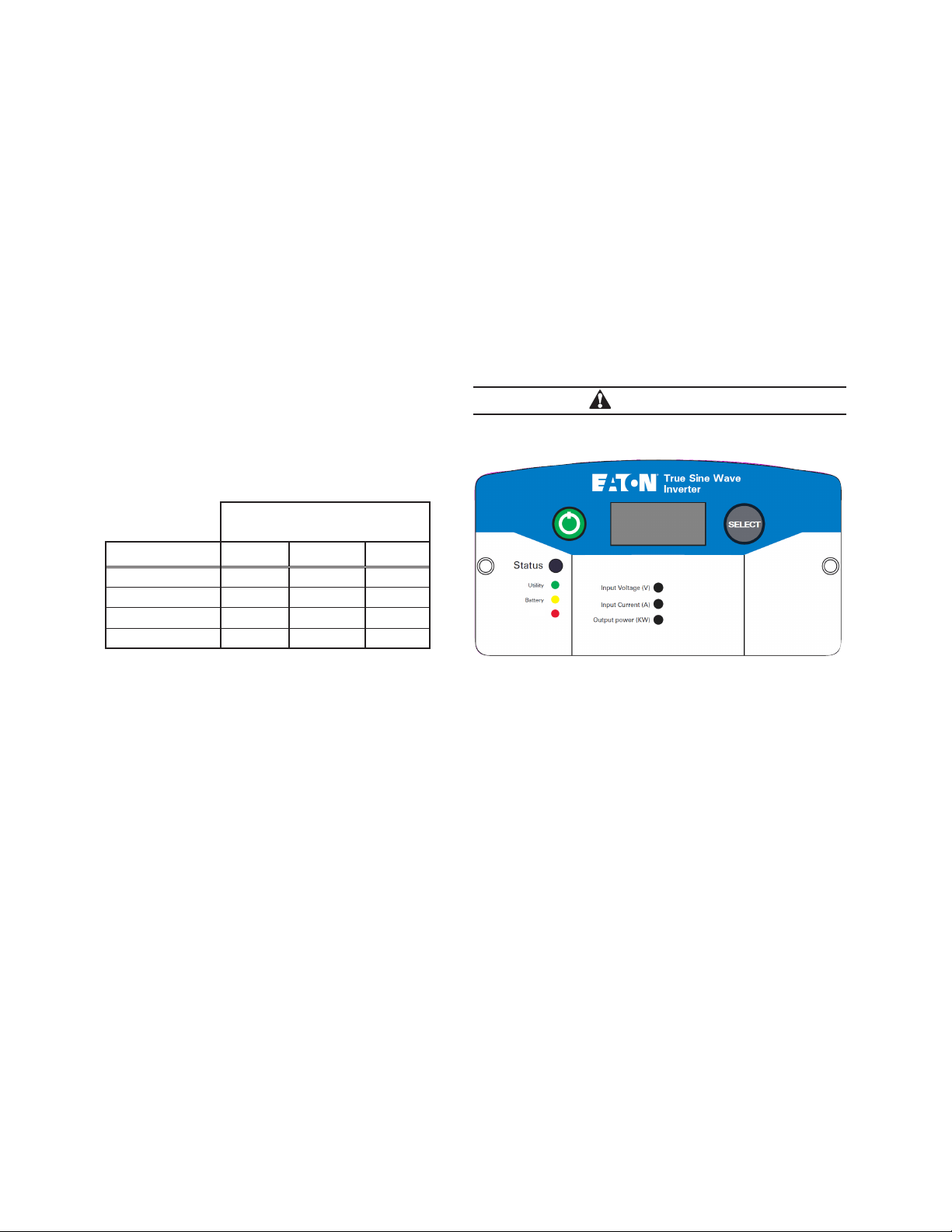
Figure 1. Inverter display panel
Power button located on the left side. SELECT button located on the right.
To change display and read current inverter settings:
By default, the screen will display the input voltage in [Volts] and the “Input Voltage (V)” LED indicator will be illuminated.
1. Press the SELECT button once. Screen displays the DC input current in [Amperes] and the “Input Current (A)” LED
indicator will illuminate.
2. Press the SELECT button once more. Screen displays the AC output power in [kilowatts] and the “Output power (KW)”
LED indicator will illuminate.
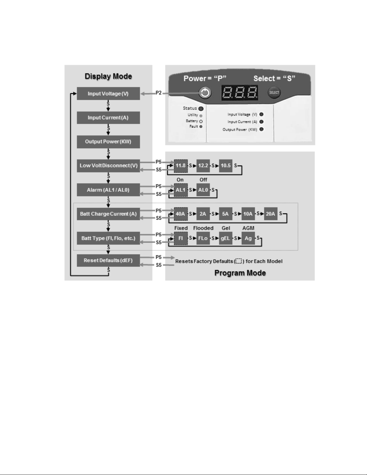
3. Press the SELECT button once more. Screen displays the Low Voltage Shut Down Level: 11.8, 12.2, 10.5.
4. Press the SELECT button once more. Screen displays the alarm setting: AL1 = Alarm on; AL0 = Alarm off.
5. Press the SELECT button once more. Screen displays the battery charge current setting.
6. Press the SELECT button once more. Screen displays the battery type for charging: Fl = Fixed; FLo = Flooded; gEL =
Gel, Ag = AGM.
ote:N If model equipped with AC bypass switch, selections will vary while in bypass mode.
2
Eaton 1250W / 1500W / 1800W Inverter Operation and Installation Guide IM SP180164 / Rev D www.eaton.com
Configuration guide
Figure 2. Setting flow chart
Showing all display and setting adjustment options
To adjust the charging current setting:
By default, the charging current is 40A.
To change the charge current setting:
1. Press and hold the green power button for approximately 2 seconds. The inverter will beep and the display will flash
the input voltage. Press the SELECT button until “40” (or current value setting) is displayed. Press and hold the POWER
button for 5 seconds.
2. Press the SELECT button to switch between the different current ratings in [Amps].
• 40 – 2 – 5 – 10 – 20
3. To choose a new setting, stop at the desired value, press and hold the select button for five seconds to memorize the
setting.
4. Confirm the new setting by not touching the inverter for approximately 5 seconds to return to inverter setting display
mode. Press SELECT button multiple times to confirm new setting(s).
Unit performance can be optimized using Table 2.
Eaton 1250W / 1500W / 1800W Inverter Operation and Installation Guide IM SP180164 / Rev D www.eaton.com
3

Configuration guide
Table 2. Charging current guidelines
AC input circuit branch
breaker or fuse size (A)
15
20
30
Charger DC current
settings (A)
2 13.5
5 12.5
10 11
20 8.5
40 3.5
2 18.5
5 17.5
10 16
20 13.5
40 8.5
2 28.5
5 27.5
10 26
20 23.5
40 18.5
Max by-pass AC current
available (A)*
ote:N *Momentarily available
To adjust alarm on/off [AL0, AL1] setting:
By default, the alarm is ON.
To change the alarm on/off setting:
1. Press and hold the green power button for approximately 2 seconds. The inverter will beep and the display will flash
the input voltage. Press the SELECT button until “AL” is displayed. Press and hold the POWER button for 5 seconds.
2. Press SELECT button to toggle between the two alarm on/off settings:
• “AL0” – this indicates the alarm is OFF
• “AL1” – this indicates the alarm is ON
3. To choose a new setting, stop at the desired value, press and hold the select button for five seconds to memorize the
setting.
4. Confirm the new setting by not touching the inverter for approximately 5 seconds to return to inverter setting display
mode. Press SELECT button multiple times to confirm new setting(s).
To adjust low voltage shutdown [ 11.8, 12.2, 10.5 ] setting:
By default, the low voltage shutdown setting is 11. 8 .
To change the low voltage shutdown setting:
1. Press and hold the green power button for approximately 2 seconds. The inverter will beep and the display will flash
the input voltage. Press the SELECT button until “11.8” (or current setting) is displayed. Press and hold the POWER
button for 5 seconds.
2. Press SELECT button to toggle between the three voltage shutdown settings:
• 11. 8
• 12.2
• 10.5
4
Eaton 1250W / 1500W / 1800W Inverter Operation and Installation Guide IM SP180164 / Rev D www.eaton.com

Configuration guide
3. To choose a new setting, stop at the desired value, press and hold the SELECT button for five seconds to memorize the
setting.
4. Confirm the new setting by not touching the inverter for approximately 5 seconds to return to inverter setting display
mode. Press SELECT button multiple times to confirm new setting(s).
To adjust battery type [ FI, FLo, gEL, Ag ] setting:
By default, the battery type is FI, Fixed.
To change the battery type setting:
1. Press and hold the green power button for approximately 2 seconds. The inverter will beep and the display will flash
the input voltage. Press the SELECT button until “FI” is displayed. Press and hold the POWER button for 5 seconds.
2. Press SELECT button to toggle between the four battery type settings:
• “FI” – this indicates Fixed setting.
• “FLo” – this indicates Flooded battery setting.
• “gEL” – this indicates Gel battery setting.
• “Ag” – this indicates AGM battery setting.
3. To choose a new setting, stop at the desired value, press and hold the SELECT button for five seconds to memorize the
setting.
4. Confirm the new setting by not touching the inverter for approximately 5 seconds to return to inverter setting display
mode. Press SELECT button multiple times to confirm new setting(s).
To reset factory default settings:
By default, the inverter settings are max charge current, AL1, 11. 8 , FI
To reset these values:
1. Press and hold the green power button for approximately 2 seconds. The inverter will beep and the display will flash
the input voltage. Press the SELECT button until “dEF” is displayed. Press and hold the POWER button for 5 seconds.
2. Press and hold the SELECT button for five seconds to memorize the setting.
3. Confirm the new setting by not touching the inverter for approximately 5 seconds to return to inverter setting display
mode. Press SELECT button multiple times to confirm new setting(s).
Eaton 1250W / 1500W / 1800W Inverter Operation and Installation Guide IM SP180164 / Rev D www.eaton.com
5
Fault codes and troubleshooting
Condition
Disconnect
Setting
Recovery
Display
AudibleAlarm
Comment
Under voltage instant shutdown
Lo, mid or hi
10.0
--
--
--
Note 3
Under voltage shutdown
Lo
10.5
12.0
E01
Beep @ 1Hz
Note 4
Under voltage shutdown
Hi
12.2
12.7
E01
Beep @ 1Hz
Note 6
Under voltage warning
Hi
12.2
12.5
E05
Beep @ 0.33Hz
--
Fault codes and troubleshooting
Inverter Section
Table 3. DC Input Warning and Shutdown
• Unit start up voltage (Lo setting): > 10.5 +/- 0.3 VDC and < 16.0 +/- 0.3 VDC
• Unit start up voltage (Mid setting): > 11.8 +/- 0.3 VDC and < 16.0+/- 0.3 VDC
• Unit start up voltage (Hi Setting): > 12.2 +/- 0.1 VDC and < 16.0 +/- 0.3 VDC
setting
Over voltage instant shutdown Lo, mid or hi 16.0 15.5 E02 Beep @ 1Hz Notes 1, 2
Under voltage warning Lo 11.0 11.3 E05 Beep @ 0.33Hz --
Under voltage shutdown Mid 11.8 12.3 E01 Beep @ 1Hz Note 5
Under voltage warning Mid 11.8 12.1 E05 Beep @ 0.33Hz --
(+/-0.3V)
(+/-0.3V)
ote:N
1. Unit will shut down instantly and restart automatically if voltage returns to less than 15.5V within 30 seconds
2. If DC voltage is not less than 15.5V within 30 seconds, unit will require manual reset by power button
3. Unit will shut off instantly if DC voltage drops below 10V regardless of settings
4. Unit will shut off if DC voltage is below shutdown for 10 seconds
5. Unit will shut off if DC voltage is below shutdown for 90 seconds
6. Unit will shut off if DC voltage is below shutdown for 2 minutes
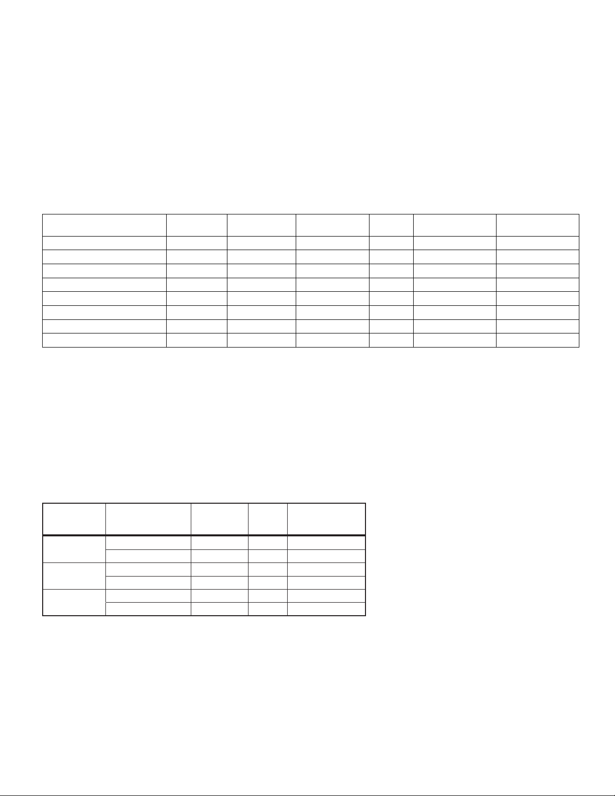
Table 4. AC output overload protection and warning shutdown
Model Condition Display Audible alarmPower (W)
12-110-1800-xx
12-110-1500-xx
12-110-1250-xx
AC output short circuit protection
A short circuit may be applied to the AC output continuously during inverter mode without damage to any components. Unit
will shut down within 10 seconds, and display will indicate ‘E03’ with the buzzer beeping @ 1 Hz.
ote:N Manual reset is required to restart Inverter after AC Overload or Short Circuit shutdown. System will automatically
reset AC Overload or Short Circuit shutdown error when utility is available. The supplemental protector or the branch
protection specified in the Installation Guide should be open under bypass short circuit output condition.
6
Warning (+/- 100W) 2000 E06 Beep @ 0.33Hz
Shutdown (+/- 100W) 2100 E03 Beep @ 1Hz
Warning (+/- 100W) 1700 E06 Beep @ 0.33Hz
Shutdown (+/- 100W) 1800 E03 Beep @ 1Hz
Warning (+/- 100W) 1450 E06 Beep @ 0.33Hz
Shutdown (+/- 100W) 1550 E03 Beep @ 1Hz
Eaton 1250W / 1500W / 1800W Inverter Operation and Installation Guide IM SP180164 / Rev D www.eaton.com
 Loading...