

Eaton 415U-2, 115E-2 Installation Manual
415U-2 wireless mesh networking I/O and gateway
installation guide
Statutory requirements
FCC: This device complies with
Part15.247 of the FCC Rules.
Operation is subject to the
following two conditions:
•
This device may not cause
harmful interference.
•
This device must accept any
interference received, including
interference that may cause
undesired operation.
FCC: Unlicensed operation limits
the radio power. High gain aerials
may only be used to compensate
for cable losses.
m WARNING - EXPLOSION
HAZARD
Do not disconnect the device while the
circuit is live unless the area is known
to be non-hazardous.
NOTE
The 415U-2 module ships from
the factory in configuration mode.
The radio locale, frequency, and RF
power need to be configured using
the embedded web pages before
use.
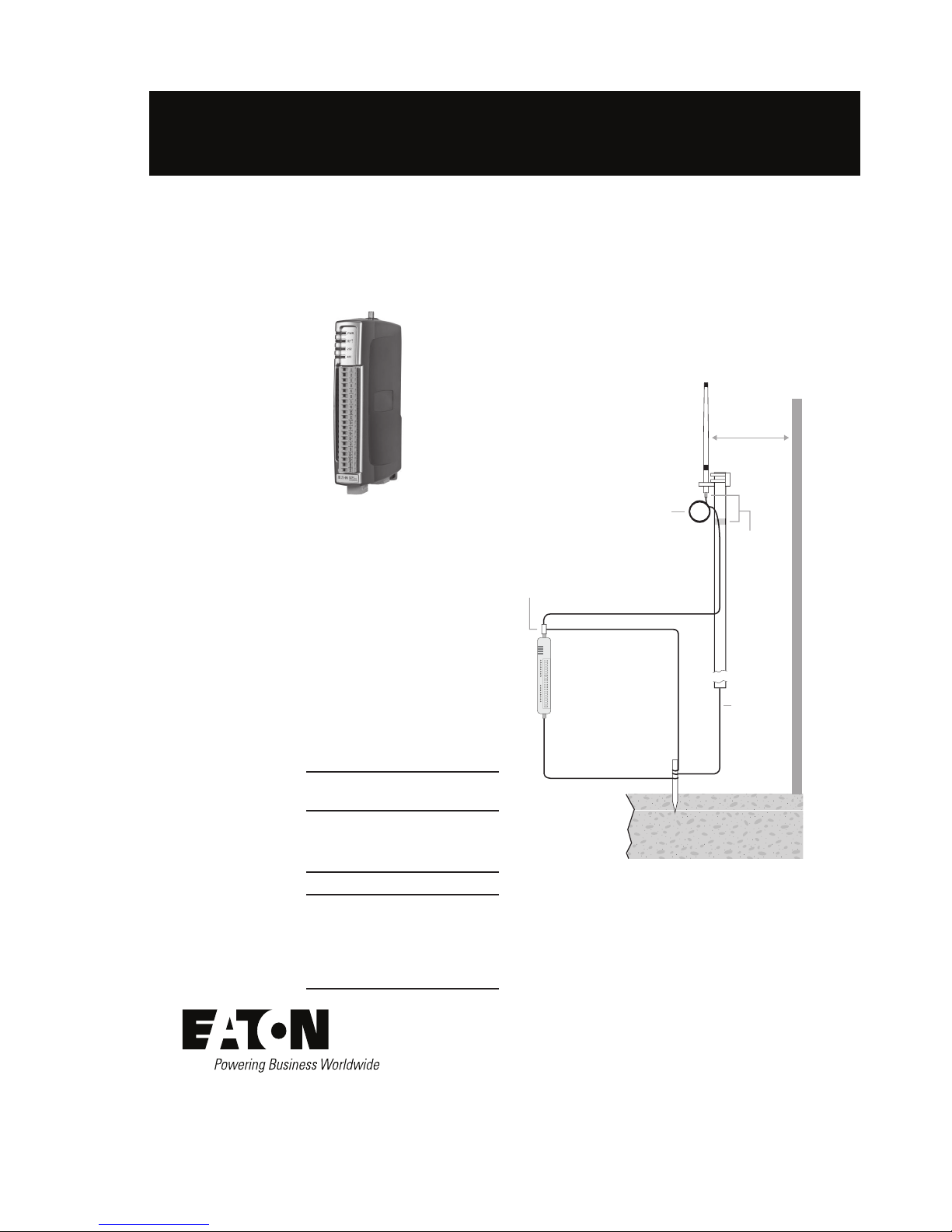
Antenna installation
Use Figure 1 as a guide for installing an antenna and attaching it
to the module.
Figure 1. Antenna installation
Earth Stake
For maximum
range, install
above local
obstructions.
Earth Conductor
at least 5 AWG
(16 mm2)
*
Wavelength:
360MHz = 32.7” (83cm)
512MHz = 22.8” (58cm)
Weatherproof
Connections
(recommended:
3M™ 23 selfbonding tape)
Mast
Coaxial Cable
GND
at least 11 AWG (4 mm2)
Stress
Relief
Loop
Antenna
*
GND
Surge Arrestor
(recommended)
415U-2
Provide good ground
connection to mast,
module, and surge
arrestor.
If ground conditions
are poor, use more
than one stake.
1 Wavelength
(minimum)
Connecting to the module for confi guration
The default settings for the 415U-2 are as follows:
•
IP Address: 192.168.0.1XX, where “XX” is the last two digits
of the serial number shown on the printed label on the side of
the module
•
Subnet Mask: 255.255.255.0
•
Default Gateway: 192.168.0.1
•
Username: user
•
Password: user
1. Connect a straight-through Ethernet cable between the
module’s Ethernet port and a PC.
2. Open Internet Explorer on the PC.
3. Type “http://” followed by the IP address of the module and
press Enter.
Instruction Leafl et IL032043EN Effective April 2015
Eaton
1000 Eaton Boulevard
Cleveland, OH 44122
United States
Eaton.com
Eaton’s wireless business
www.eaton.com/wireless
Eaton is a registered trademark.
All other trademarks are propert y
of their respective owners.
415U-2 wireless mesh networking I/O and gateway installation guide
© 2015 Eaton
All Rights Reserved
Printed in USA
Publication No. IL032043EN
April 2015
Instruction Leafl et IL032043EN
Effective July 2015
NOTE
All connections must be SELV <50Vac and <120Vdc.
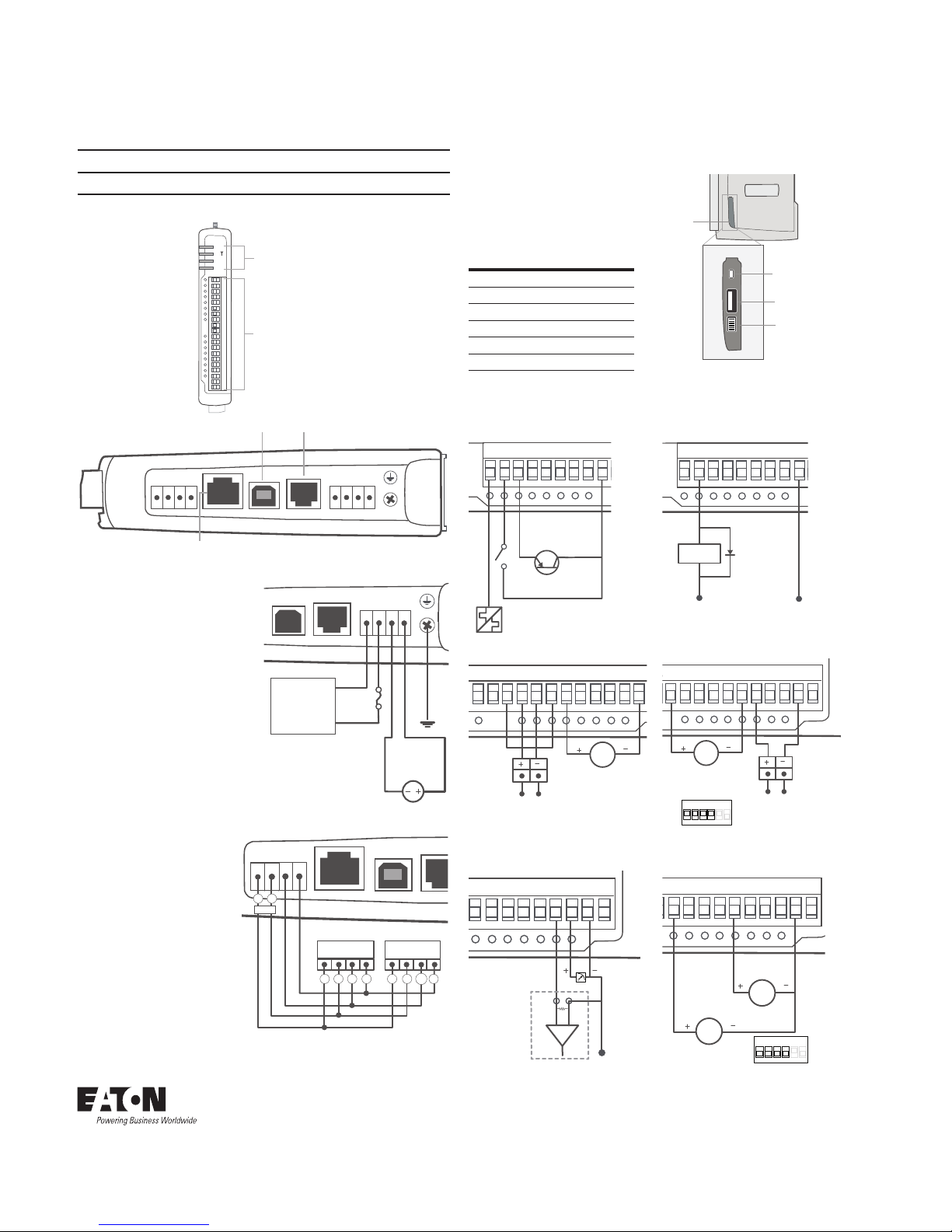
The following illustrations show the ports on the 415U2.
PWR
RF
232
485
LED Indicator
Lights
I/O Connectors
RJ-45 Ethernet Port
(connects to hub or switch)
USB Port RS-232 Port
ETHERNET USB RS232 SUPPLY
+
-
GND
BAT SUP
SUP
+
B A
-
+
Power supply wiring
The ground (GND) and “SUP–“
terminals are connected
internally to the ground terminal.
Connect the screw terminal on
the end plate to ground for surge
protection.
Expanson I/O power and RS-485 serial connection
An on-board RS-485
terminating resistor provides
line attenuation for long runs.
Place terminating resisters
at each end of the RS-485
cable.
Confi guration switches
Use the DIP switches in the
side access panel to select
analog input voltage and
current, external boot, and
default configuration settings.
DIP DESCRIPTION
1 AI3 current/voltage
2 AI3 current/voltage
3 AI4 current/voltage
4 AI4 current/voltage
5 Unused
6 Enables default configuration
Input and output connections
The digital input/output channels can be wired as inputs or outputs.
Digital input Digital output
Transistor
Switch
Device
Voltage-free Contact
TTL CMOS
Output
D1 D3 D4 D5 D6 D7 D8
GND
+24V
D2
DC Load
+ –
D1 D3 D4 D5 D6 D7 D8
GND
+24V
D2
Differential current inputs (Al1, Al2) Single-ended current input (Al3, Al4)
mA
Loop-Powered
Sensor
Exernally
Powered
Sensor
Power Supply
D8
GND +24V
AI1+AI1_AI2+AI2
_
AI3 AI4
AO1+AO2
+
GND
+24V
mA
Loop-Powered
Sensor
Power Supply
Externally
Powered
Sensor
DIP Switch Setting
for Current IP
AI1+AI1_AI2+AI2
_
AI3 AI4
AO1+AO2
+
GND +24V
1 2 3 4 5 6
ON
Analog output Single-ended voltage input
AI
PLC
COM
_
AI2+AI2
_
AI3 AI4
AO1+AO2
+
GND +24V
0–25V
Sensor
0–5 Vdc
Sensor
AI1+AI1_AI2+AI2
_
AI3 AI4
AO1+AO2
+
GND +24V
V
V
DIP Switch Setting
for Voltage IP
ON
1 2 3 4 5 6
ETHERNET
USB
RS232
B A
-
+
115S-xx 115S-xx
RS-485
B A
B A B A
-
+
-
+
USB RS232 SUPPLY
+
-
GND
BAT SUP
SUP
+
15-30 Vdc
Supply
3A Fuse
Optional
10.8–15 Vdc
Lead Acid
Battery
–
+
USB Host
Factory Boot
Switch
%QPʙIWTCVKQP
Switches
Side
Access
Panel
 Loading...