

Eaton 10250T/91000T, E34 Installation Instructions And Operation Manual
Effective February 2018
Supersedes July 2011
Instructions and Operation P20442
Heavy Duty Oiltight Selector Switch
Units - 10250T/91000T or E34
®
Underwriters Laboratories Listed
For use on a flat surface of Type
1, 2, 3, 3R, 4, 4X, 12 and 13
enclosures. IP 65
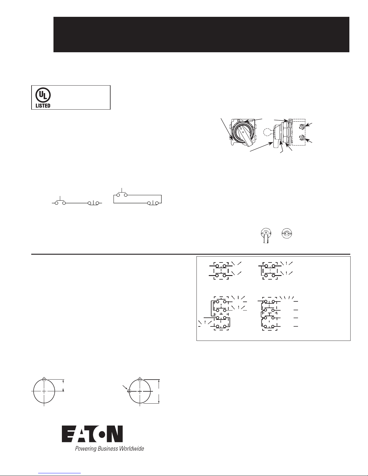
ASSEMBLY INSTRUCTIONS
1. Select the desired schematic circuit function from the chart below and
note in your cam column the type of contacts, N.O. or N.C., the “A” and
“B” circuit locations, and any series or parallel jumper connections the may
be required.
2. Choose contact blocks that have the required schematic circuits and
assemble in any convenient sequence that fullls the “A” and “B” circuit
location requirements.
NOTE: Single circuit contact blocks, if used, must be last in the stack and
positioned so that the plunger motion is transmitted through.
3. Make the indicated series or parallel jumper connections.
(10250T/91000TA70,TA71).
4. If this operator was received without an operating cap, assemble the
separately purchased cap, assemble the separately purchased cap and secure
with the screws provided.
NOTES: Single, double and 2NO-2NC contact blocks are available. Six contacts
can be stacked in each of the two circuit locations making a maximum of
twelve circuits possible.
For additional selector switch explanation ask for manual NU-118.
The two sections of the operating cam of this selector switch work
independently, so it is important that the contact blocks be oriented with
their plungers in the correct “A” and “B” circuit locations. The sketch below
identies these positions with respect to the locatin nib or marked top.
Sketch shows VERTICAL MOUNTING. For HORIZONTAL MOUNTING
loosen the set screw and assemble so that the locating nib is at the left.
ILLUMINATED GASKET INSTRUCTIONS This operator was shipped with
the gasket oriented for VERTICAL MOUNTING using lever lens and the
new type knob lens.
For HORIZONTAL MOUNTING (or VERTICAL MOUNTING using the old
type knob) carefully peel the lens gasket, rotate it 90°, and press onto the
operator. (Lens screws will now thread into alternate holes).
LAMB REMOVAL TOOL For Trans. Type Cat. No. 10250TA74 for Full Voltage
Type E30KV1.
1. Drill mounting hole for vertical or horizontal mounting per one of the gures
above.
2. ensure sealing gasket is in the place on the operator. Align location nib
of the operator with notch in the panel and insert operator through mounting hole.
3. Place legend plate and mounting nut over operator. Tighten mounting
nut. If applicable assemble buttons to operator. Tighten securely (5 ft-lbs)
(6.8 Nm).
4. Torque terminals to 12 in/lbs (1.4 Nm).
For ease of assembly, we recommend the following tools:
91000T/10250TA95 (for 10250T/91000T octagonal nut, E29 and E30 line)
E22CW (for 10250T/91000T octagonal nuts, E22, E30 and E34)
5. Torque contact block stacking screws to 5-7 in/lbs (0.57- 0.79 Nm)
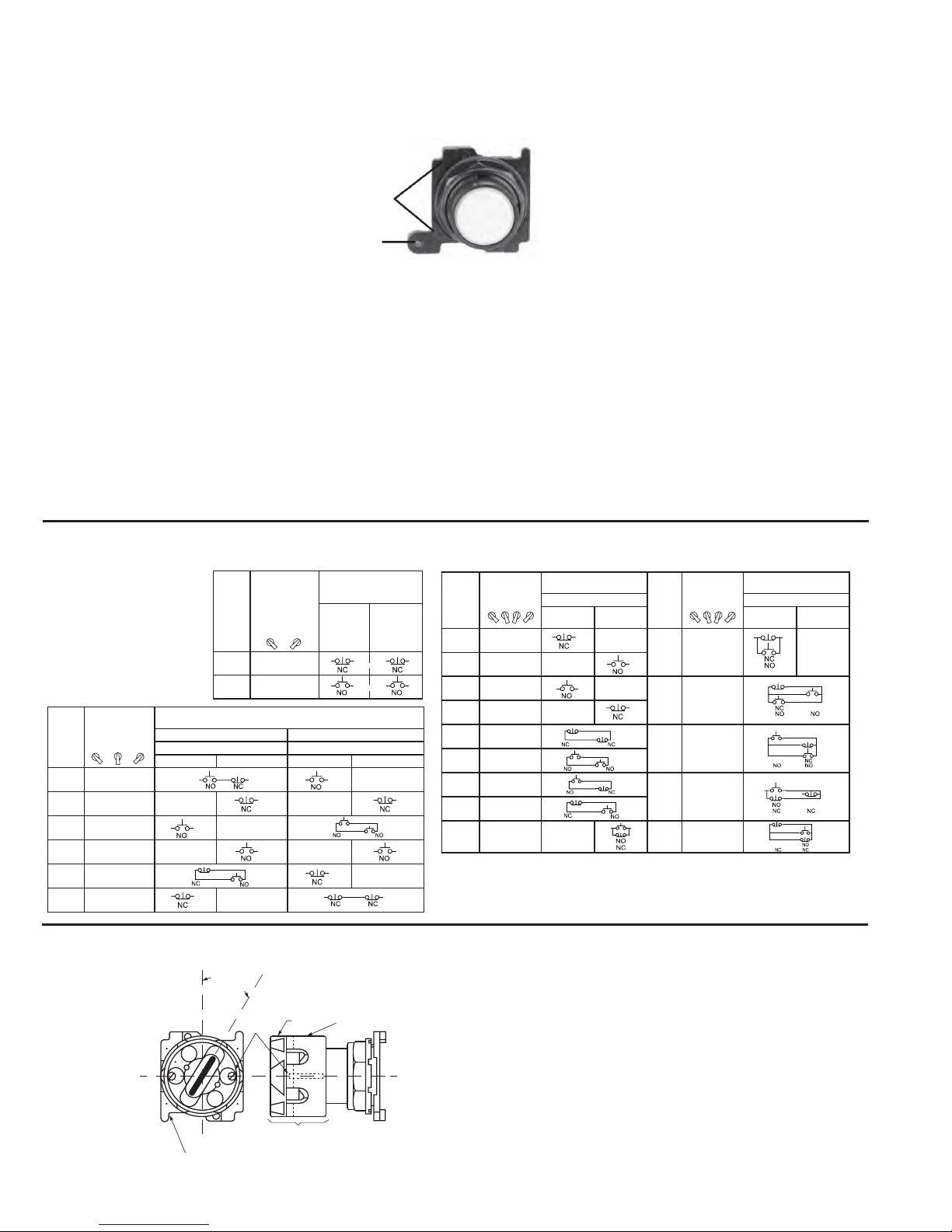
The selector switch operator in this package may not be complete. A knob,
lever, coin slot or knob type lens operating cap is required wich may be
merchandised and packaged separately.
WIRING INSTRUCTIONS
The illustration shows the circuit conditions that result for each position of
the selector switch.
Heavy lines indicates
costumers connections.
Light lines are factory
installed jumpers
X=circuit closed
O=circuit open
L=Left
C=Center
R=Right
1-2-3-4=4 position switch
ASSEMBLY INSTRUCTIONS
US 60/75°C COPPER CONDUCTORS ONLY
LIGHT MODULE OF CONTACT BLOCK
Vertical Mounting
Lever
New
Knob
For Replacement Gasket Order PT #32-803
Grounding nibs Locating nib
or top
Set screw
Use 1/16”
Allen Wrench
Circuit
“A”
Circuit
“B”
Retaining Nut
To be changed in Coin
Slot Assembly
Operating cab
Knob, Lever, Coin, Slot, Key or Knob
Type Lense
1A
1B
X O
O X
L R
10250T/91000T20
SERIES OR E34
1A
1B
X O O
L C R
COM
10250T/91000T21
SERIES OR E34
O O X
10250T/91000T22
SERIES OR E34
X O O
O O X
COM
L C R
O X O
10250T/91000T46
SERIES OR E34
O O O X
O O X O
O X O O
X O O O
COM
1 2 3 4
.60 (15.2 mm)
1.20 (30.5 mm)
.136 (3.5 mm) dia. hole or
.180 (4.6 mm) rectangular
notch
VERTICAL MOUNTING
HORIZONTAL MOUNTING
4 Position
Combination
No.
Desired Circuit
Operation
X Circuit Closed
O Circuit Open
Contact Blocks Required to
Accomplish Circuit Function
Combination
No.
Desired Circuit
Operation
X Circuit Closed
O Circuit Open
Contact Blocks Required to
Accomplish Circuit Function
Mounting Location Mounting Location
Top Plunger A Bottom
Plunger B
Top Plunger A Bottom
Plunger B
1 X O O O
10 X O X O
2 O X O O
3 O O X O
11 X X X O
4 O O O X
5 X O O X
12 O X X X
6 O X X O
7 O O X X
13 X O X X
8 X X O O
9 O X O X 14 X X O X
3 Position
Combination
No.
Desired Circuit
Operation
X Circuit Closed
O Circuit Open
Contact Blocks Required to Accomplish Circuit Function
(Jumpers must be installed where indicated)
Operator with Cam Code #2 Operator with Cam Code #3
Mounting Location Mounting Location
Top Plunger A Bottom Plunger B Top Plunger A Bottom Plunger B
1 X O O
2 X X O
3 X O X
4 O O X
5 O X X
6 O X O
2 Position
Combination
No.
Desired Circuit
Operation
X Contacts
Closed
O Contacts
Open
Contact Blocks Required
to Accomplish Circuit
Function
Top PlungerABottom
Plunger
B
1 X O
2 O X
2
Instructions and Operation P20442
Effective February 2018
Heavy Duty Oiltight Selector Switch
SWITCH UNITS-10250T/91000T OR E34
EATON CORPORATION www.eaton.com
GENERAL
With any electrical component there is the possibility an external factor (loose wire, moisture, etc.) can cause a short circuit between the component and
ground. If the device is adequately grounded, the condition causes the protective fuse or circuit breaker to open and remove the potential. If not, an electrical
hazard may remain unnoticed.
GROUNDING NIBS – 10250T
This 10250T device is designed to make direct metallic contact to the rear of the panel (with no interfere with component-to-panel ground continuity). As
a further aid in establishing an electrical ground, the device has 4 metal points, “grounding nibs” designed to penetrate most paint or other protective coatings.
Penetration of these nibs is dependent upon the torque applied to the mounting nut. Recommended torque is 5 ft.lbs (6.8Nm). More or less may be necessary
to penetrate the specic type of thickness of your panel coating. Test for continuity to ground after installation. If a short circuit to ground does occur, the
fault should be corrected and the device replaced.
GROUNDING KITS
For grounding 10250T devices to non-metallic panels or metal panels having excessive surface coating or for grounding E34 with any panel we offer the
following grounding kits which provide for a separate grounding circuit, daisy chained between components and then to ground. Use 10250TKG1.
EARTH TERMINALS- 91000T/E34
These devices are supplied with an earth/ground terminal incorporated. These devices have a 6-32 terminal screw and will accommodate ring type terminations
for bonding to international specications.
Select cam code giving
simplest contact block
arrangement for circuit(s)
required.
-Ordinarily, these operators should not be used with overlap and early closing contact
blocks (10250T/91000T55, T56, T57 and T58). Contact local EATON sales ofce on
specic application.
CONTACT BLOCK SELECTION CHART
INSTRUCTIONS FOR THE ASSEMBLY OF THE PADLOCK ATTACHMENT E34TA11, 10250T/91000TA11
TO KNOB OPERATED HEAVY DUTY OIL TIGHT SELECTOR SWITCH OPERATORS
1. With the knob of the selector positioned per dimension “A”, place the
padlock attachment over the knob with the mounting screws located as
shown in the illustration.
2. Tighten the mounting screws alternately and uniformly to prevent the
attachment from being assembled skewed.
3. The outer lock ring can now be turned to any desired selector position.
there are provisions for 5 padlocks.
Dimension “A”- For 2 or 3 position selector switch operators. Locate the
knob half way between clockwise and center positions.
GROUNDING OF 10250T/91000T AND E34
COMPONENTS
Nib
Earth
Terminal
FOR HORIZONTAL MOUNTED UNITS THIS BASE IS TURNED 90 DEG.
HOWEVER, KNOB POSITION AND ASSEMBLY INSTRUCTIONS SHOWN
HERE APPLY
PADLOCK
ATTACHMENT
FOR ASSEMBLING SEE ITEM
2 INSTRUCTIONS
SELECTOR
KNOB
POSITION
DIM “A”
MOUNT-
ING
SCREWS
OUTER
LOCK RING
INTER LOCK
RING
OR
OR
OR
 Loading...