

Eaton 1000L, 1000LXL, 1500L, 1500LXL, 3000L User Manual
...

Contents :
1. INTRODUCTION................................................................................................1
2. IMPORTANT SAFETY INSTRUCTIONS...........................................................2
3. SYSTEM DESCRIPTION...................................................................................4
3.1 Front Panel......................................................................................................4
4. CONNECTION AND OPERATION....................................................................6
5. TROUBLESHOOTING.......................................................................................8
6. MAINTENANCE.................................................................................................9
6.1 Operation........................................................................................................9
6.2 Storage............................................................................................................9
7. TECHNICAL DATA.........................................................................................10
7.1 Electrical specifications..............................................................................10
7.2 Typical stored energy time (Battery mode)...............................................10
7.3 Dimensions and weights.............................................................................10
7.4 EMC...............................................................................................................11
7.5 Communication Port....................................................................................11
7.5.1 RS232 Interface.........................................................................................11
7.5.2 AS400 Interface.........................................................................................12
7.6 Operating environment................................................................................12
8. APPENDIX.......................................................................................................13

---1---
The On-Line-Series is an uninterruptible power supply incorporating double-converter technology. It
provides perfect protection specifically for Novell, Windows NT and UNIX servers.
The double-converter principle eliminates all mains power disturbances. A rectifier converts the alter-
nating current from the socket outlet to direct current. This direct current charges the batteries and
powers the inverter. On the basis of this DC voltage, the inverter generates a sinusoidal AC voltage
which permanently supplies the loads.
Computers and periphery are thus powered entirely independently of the mains voltage. In the event
of power failure, the maintenance-free batteries power the inverter.
1. INTRODUCTION

---2---
Transport
● Please transport the UPS system only in the original packaging (to protect against shock and
impact).
Set-up
● Condensation may occur if the UPS system is moved directly from a cold to a warm environment.
The UPS system must be absolutely dry before being installed. Please allow an acclimatisation
time of at least two hours.
● Do not install the UPS system near water or in damp environments.
● Do not install the UPS system where it would be exposed to direct sunlight or near heat.
● Do not block off ventilation openings in the UPS system’s housing.
Installation
● Connect the UPS system only to an earthed shockproof socket outlet. Please note the special
installation aspects for the permanently connected unit in Chapter 4 “Connection and Operation”.
● The building wiring socket outlet (shockproof socket outlet) must be easily accessible and close to
the UPS system.
● Do not connect domestic appliances such as hair dryers to UPS output sockets.
2. IMPORTANT SAFETY INSTRUCTIONS
● Intended for Installation in a Controlled Environment.
● Servicing of Batteries Should be Performed or Supervised by Personnel Knowledgeable of Batteries
and the Required Precautions. Keep Unauthorized Personnel Away from Batteries.
● CAUTION - To reduce the risk of fire, unit input connect only to a circuit provided with branch circuit
overcurrent protection for 30 amperes rating in accordance with the National Electric Code, ANSI/NFPA
70”.( For Models 3000LXL )
● When Replacing Batteries, Replace With the Same Number and Type.
● CAUTION - Do Not Dispose of Battery or Batteries in a Fire. The Battery May Explode.
● CAUTION - Do Not Open or Mutilate the Battery or Batteries. Released Electrolyte is Harmful to the Skin
and Eyes. It May be Toxic.
● CAUTION - A Battery can present a Risk of Electrical Shock and High Short Circuit Current. The Following
Precautions Should be Observed When Working on Batteries:
A. Remove watches, rings, or other metal objects.
B. Use tools with insulated handles.
C. Wear rubber gloves and boots.
D. Do not lay tools or metal parts on top of batteries.
E. Disconnect charging source prior to connecting or disconnecting battery terminals.
● Use 10 AWG (for Model 3000LXL) ,90°C copper wire and 22 lb-in Torque force when connecting to
terminal block.
SAVE THESE INSTRUCTIONS
This Manual Contains Important Instructions that should be Followed during Instal-
lation and Maintenance of the UPS and Batteries.

---3---
● Do not connect appliances or items of equipment which would overload the UPS system (e.g. laser
printers) to the UPS outlet socket.
● Place cables in such a way that no one can step on or trip over them.
Operation
● Do not disconnect the mains cable on the UPS system or the building wiring socket outlet (shockproof
socket outlet) during operations since this would cancel the protective earthing of the UPS system
and of all connected loads.
● The UPS system features its own, internal current source (batteries). The UPS output sockets may
be electrically live even if the UPS system is not connected to the building wiring socket outlet.
● In order to fully disconnect the UPS system, first press the Standby switch then disconnect the
mains lead or, on the permanently connected unit , isolate the incoming feeder.
● Ensure that no fluids or other foreign objects can enter the UPS system.
Maintenance, servicing and faults
● The UPS system operates with hazardous voltages. Repairs may be carried out only by qualified
maintenance personnel.
● CAUTION - risk of electric shock. Even after the unit is disconnected from the mains power supply
(building wiring socket outlet), components inside the UPS system are still connected to the battery and are still electrically live and dangerous. Before carrying out any kind of servicing and/or
maintenance, disconnect the batteries and verify that no current is present.
● Only persons adequately familiar with batteries and with the required precautionary measures
may exchange batteries and supervise operations. Unauthorised persons must be kept well away
from the batteries.
● CAUTION - risk of electric shock. The battery circuit is not isolated from the input voltage. Hazard-
ous voltages may occur between the battery terminals and the ground. Before touching, please
verify that no voltage is present!
● Batteries may cause electric shock and have a high short-circuit current. Please take the precau-
tionary measures specified below and any other measures necessary when working with batteries:
- remove wristwatches, rings and other metal objects.
- use only tools with insulated grips and handles.
● When changing batteries, install the same number and same type of batteries.
● Do not attempt to dispose of batteries by burning them. This could cause battery explosion.
● Do not open or destroy batteries. Escaping electrolyte can cause injury to the skin and eyes. It
may be toxic.
● Please replace the fuse only by a fuse of the same type and of the same amperage in order to
avoid fire hazards.
● Do not dismantle the UPS system.
2. IMPORTANT SAFETY INSTRUCTIONS
---4---
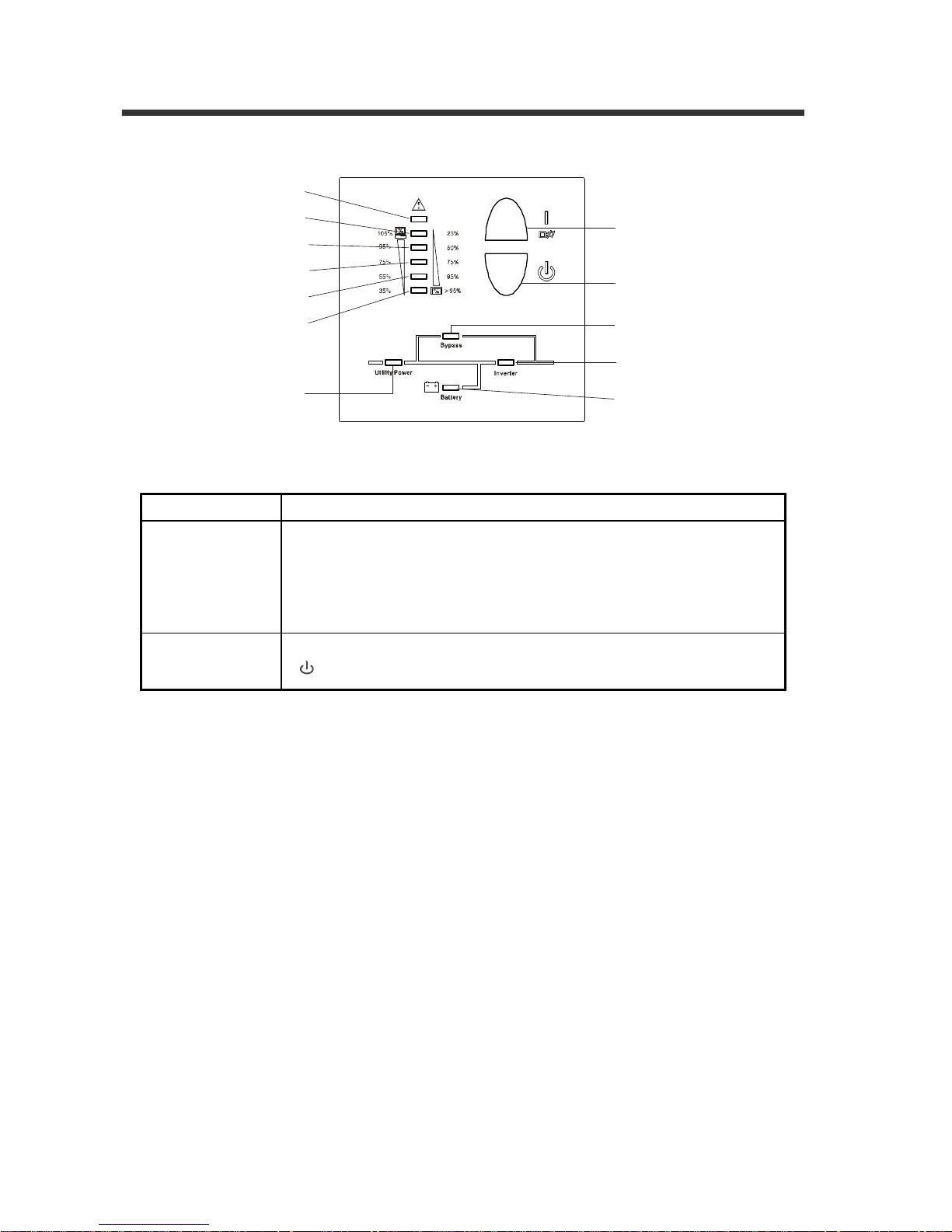
3.1 Front Panel
Switch Function
ON -
Switch
1. Turn on UPS system:
By pressing the ON-Switch “ I ” the UPS system is turned on.
2. Deactivate acoustic alarm :
By pressing this switch an acoustic alarm can be deactivated.
Standby
- Switch
The UPS system switches to Standby mode when the Standby button
“ ” is pressed. Then the inverter is off.
Figure 1 : Display panel
Indicator 1(Fault)
Indicator 2
Indicator 3
Indicator 4
Indicator 5
Indicator 6
Utility Power
Indicator
Power Off
Power On/
Alarm Silence
Bypass Indicator
Inverter Indicator
Battery Indicator
3. SYSTEM DESCRIPTION
 Loading...