

Eaton 1000H(XL), 2000HXL, 10000HXL, 3000HXL, 6000HXL User Manual
...
--24--
www.eaton.com/dxups
USER MANUAL
ON LINE UPS
1000H(XL)/2000H(XL)/3000H(XL)/6000H(XL)/10000H(XL)
Uninterruptible Power Supply

Contents
1. Safety and EMC Instructions.............................................................................................................1-3
1.1 Installation........................................................................................................................................1
1.2 Operation.........................................................................................................................................2
1.3 Maintenance, Servicing and Faults..................................................................................................2
1.4 Transport .........................................................................................................................................3
1.5 Storage ............................................................................................................................................3
1.6 Standards ........................................................................................................................................3
2. Description of Commonly Used Symbols ...........................................................................................4
3. Introduction 1000H(XL)/2000H(XL)/3000H(XL)....................................................................................5
4. System Description...............................................................................................................................6
5. Connection and Operation...............................................................................................................7-10
5.1 Connection and Operation for 1000H(XL)/2000H(XL)/3000H(XL)..............................................7-10
6. Trouble Shooting.................................................................................................................................11
7. Maintenance.........................................................................................................................................12
7.1 Operation.......................................................................................................................................12
7.2 Storage ..........................................................................................................................................12
8. Technical data.................................................................................................................................13-14
8.1 Electrical Specifications.................................................................................................................13
8.2 Operating Environment..................................................................................................................13
8.3 Typical Stored Energy Time (Typical values at 25°C in minutes:) ...............................................13
8.4 Dimensions and Weights...............................................................................................................14
9. Introduction 6000H(XL)/10000H(XL)...................................................................................................15
9.1 Product Specification and Performance.........................................................................................15
10. Installation.....................................................................................................................................16-19
10.1 Unpacking and Inspection ...........................................................................................................16
10.2 Input and Output Power Cords and Protective Earth Ground Installation...............................16-17
10.3 Operating Procedure for Connecting the Long Backup Time Model UPS with the External
Battery .........................................................................................................................................18
10.4 Parallel Operation........................................................................................................................19
11. Operation and Operating Mode...................................................................................................20-24
11.1 Operation................................................................................................................................20-24
12. Battery Maintenance..........................................................................................................................25
13. Notes for Battery Disposal and Battery Replacement ..................................................................26

14. Trouble Shooting...............................................................................................................................27
15. Operating Mode for all Models ....................................................................................................28-29
16. Communication Port .........................................................................................................................30
17. Software for all models……………………………………………………………………………………. .31
18. Appendix .......................................................................................................................................32-36
Appendix1-Display Panel(for 6000H(XL)/10000H(XL)) ................................................................32
Appendix2-The Corresponding Form of the LED Display for 6000H(XL)/10000H(XL) ....................33
Appendix3-Back Panel.................................................................................................................34-36
1
1. Safety and EMC instructions
Please read carefully the following user manual and the safety instructions
before installing the unit or using the unit!
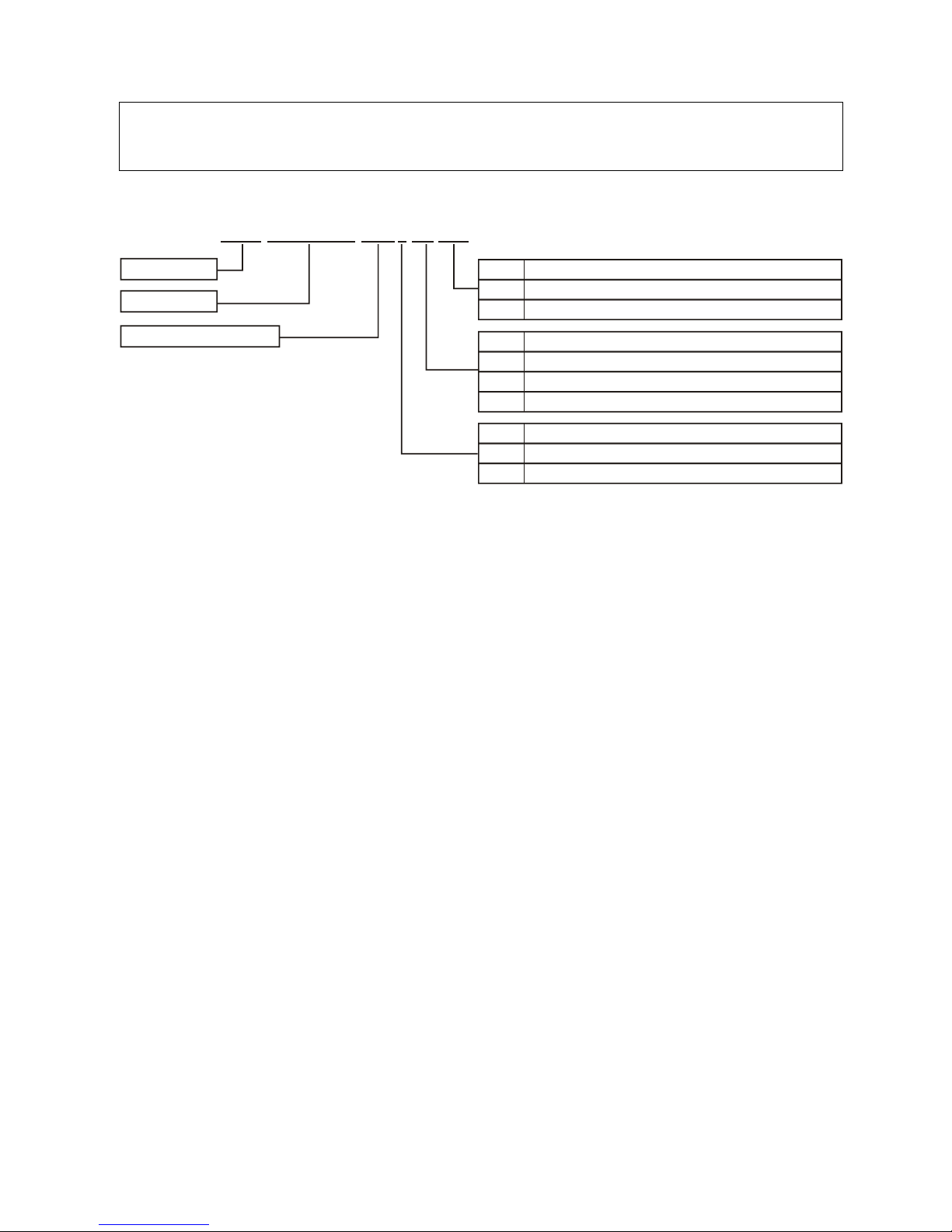
This manual is designed for the product that the model designation rules as followed:
The description followed in this text is make example with Eaton
1000H(XL)/2000H(XL)/3000H(XL)/6000H(XL)/10000H(XL).
1.1 Installation
★ Condensation may occur if the UPS is moved directly from a cold to a warm environment.
The UPS must be absolutely dry before being installed. Please allow an acclimatization
time of at least two hours.
★ Do not install the UPS near water or in damp environment.
★ Do not install the UPS where it would be exposed to direct sunlight or near heat.
★ Do not block ventilation openings in the UPS’s housing.
★ Do not connect appliances or items of equipment which would overload the UPS (e.g. laser
printers, etc) to the UPS outlet sockets.
★ Place cables in such a way that no one can step on or trip over them.
◇ For 1000H / 2000H / 3000H
★ Socket-outlets and socket of batteries are earthed by the input power cord, please insert the
power cord into mains socket before using of UPS.
★ Connect the UPS only to an earthed shockproof socket outlet.
★ The building wiring socket outlet (shockproof socket outlet) must be easily accessible to
close to the UPS.
★ This is operator installable .
Eaton E Series DX 1000H (X) (XL)
Brand name
UPS series
Output capacity(VA)
Code Batteries internal or external
Nil Standard model with batteries internal
XL
Long backup time model with batteries external
Code
Receptacle and plut type
B
Brazilian type
I
Indian type
... ..
Code
Voltage level
H 220/230/240V
L
110/115/120V

2
◇ For 6000H / 10000H
★ UPS has provided earthed terminal, in the final installed system configuration, equipotential
earth bonding to the external UPS battery cabinets.
★ An integral single emergency switching device which prevents further supply to the load by
the UPS in any mode of operation should be provided in the building wiring installation.
★ An appropriate disconnect device as short-circuit backup protection should be provided in
the building wiring installation.
★ For three-phase equipment connection to an IT power system, a four-pole device which
disconnect all phase conductors and the neutral conductor should be provided in the
building wiring installation.
★ This is permanently connected equipment, it must be installed by qualified maintenance
personnel.
★ Earth connection essential before connecting to the building wiring terminal.
1. Safety and EMC instructions
1.2 Operation
★ Do not disconnect the mains cable on the UPS or the building wiring socket (grounded
shockproof socket) during operation as this would remove the ground to the UPS and of all
connected loads.
★ The UPS output socket or output terminal block may be electrically lived even if the UPS
system is not connected to the building wiring terminal.
★ In order to fully disconnect the UPS, first press the Standby button, then disconnect the
mains lead.
★ Ensure that no liquid or other foreign objects can enter the UPS.
★ The UPS can be operated by any individuals with no previous experience.
1.3 Maintenance, servicing and faults
★ The UPS operates with hazardous voltages. Repairs may be carried out only by qualified
maintenance personnel.
★ Caution - risk of electric shock. Even after the unit is disconnected from the mains power
supply (building wiring socket), components inside the UPS are still connected to the battery
which are potentially dangerous.
★ Before carrying out any kind of service and/or maintenance, disconnect the batteries.
Verify that no current is present and no hazardous voltage exists in the capacitor or BUS
capacitor terminals.
★ Batteries must be replaced only by qualified personnel.
★ Caution - risk of electric shock. The battery circuit is not isolated from the input voltage.

3
Hazardous voltages may occur between the battery terminals and the ground. Verify that no
voltage is present before servicing!
★ Batteries have a high short-circuit current and pose a risk of shock. Take all precautionary
measures specified below and any other measures necessary when working with batteries:
- remove all jewellery, wristwatches, rings and other metal objects
- use only tools with insulated grips and handles.
★ When changing batteries, replace with the same quantity and the same type of batteries.
★ Do not attempt to dispose of batteries by burning them. It could cause explosion.
★ Do not open or destroy batteries. effluent electrolyte can cause injury to the skin and eyes. It
may be toxic.
★ Please replace the fuse only by a fuse of the same type and of the same amperage in order
to avoid fire hazards.
★ Do not dismantle the UPS, except the qualified maintenance personnel.
1. Safety and EMC instructions
1.4 Transport
★ Please transport the UPS only in the original packaging (to protect against shock and
impact).
1.5 Storage
★ The UPS must be stockpiled in the room where it is ventilated and dry.
1.6 Standards
Only the units with CE markings are comply with the following standards:
◇ For 1000H(XL) / 2000H(XL) / 3000H(XL)
* Safety
IEC/EN 62040-1-1
* EMI
Conducted Emission...............................:IEC/EN 50091-2 CLASS B
Radiated Emission..................................:IEC/EN 50091-2 CLASS B
Harmonic Current....................................:IEC/EN 61000-3-2
Voltage Fluctuation and Flicker...............:IEC/EN 61000-3-3
*EMS
ESD........................................................:IEC/EN 61000-4-2 Level 4
RS..........................................................:IEC/EN 61000-4-3 Level 3
EFT.........................................................:IEC/EN 61000-4-4 Level 4
SURGE..................................................:IEC/EN 61000-4-5 Level 4
Low Frequency Signals.........................:IEC/EN 61000-2-2
4
◇ For 6000H(XL) / 10000H(XL)
* Safety
IEC/EN 62040-1-1
* EMI
Conducted Emission.................................:IEC/EN 50091-2 Current>25A
Radiated Emission....................................:IEC/EN 50091-2 Current>25A
* EMS
ESD.......................................................:IEC/EN 61000-4-2 Level 4
RS.........................................................:IEC/EN 61000-4-3 Level 3
EFT........................................................:IEC/EN 61000-4-4 Level 4
SURGE.................................................:IEC/EN 61000-4-5 Level 4
Low Frequency Signals.........................:IEC/EN 61000-2-2
Warning: This is a product for restricted sales distribution to informed partners.
Installation restrictions or additional measures may be needed to prevent
disturbances.
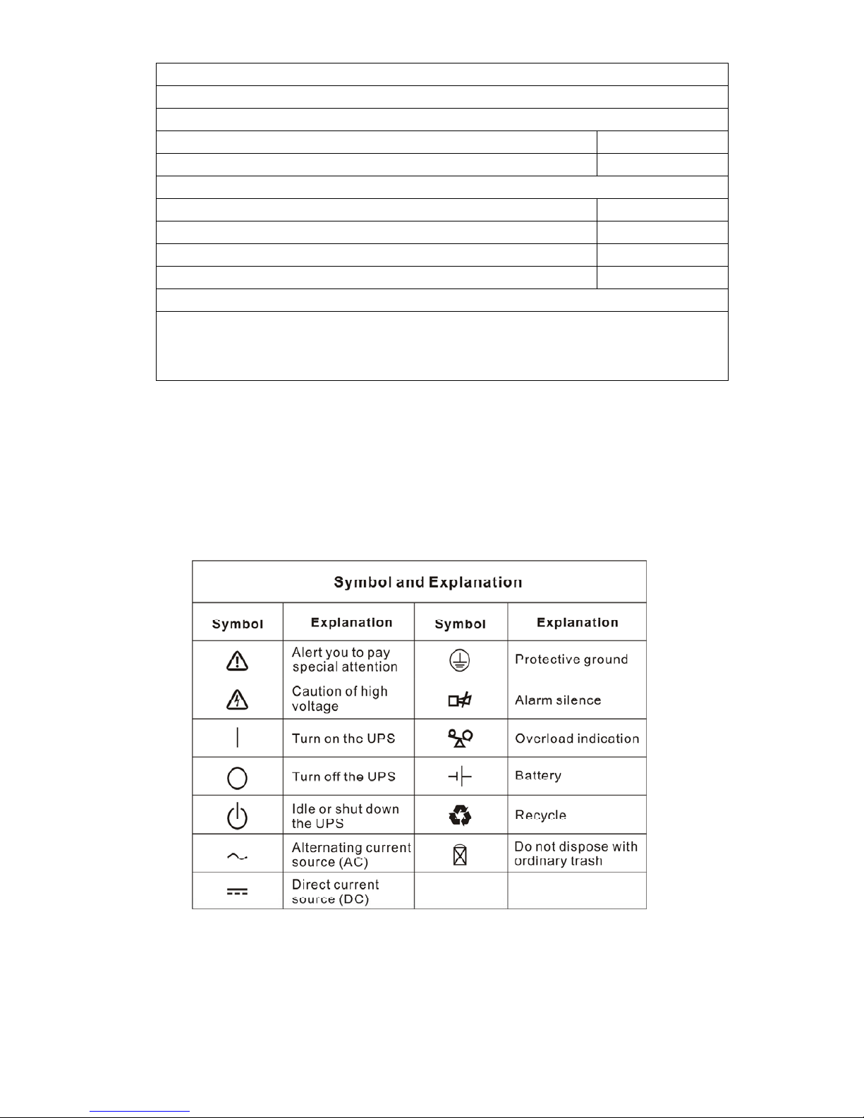
2. Description of commonly used symbols
Some or all of the following symbols may be used in this manual. It is advisable to familiarize
yourself with them and understand their meaning:

5
3. Introduction – 1000H(XL)/2000H(XL)/3000H(XL)
This On-Line-Series is an uninterruptible power supply incorporating double-converter
technology. It provides perfect protection specifically for Novell, Windows NT and UNIX
servers.
The double-converter principle eliminates all mains power disturbances. A rectifier converts
the alternating current from the socket outlet to direct current. This direct current charges the
batteries and powers the inverter. On the basis of this DC voltage, the inverter generates a
sinusoidal AC voltage, which permanently supplies the loads.
Computers and periphery are thus powered entirely by the mains voltage. In the event of
power failure, the maintenance-free batteries power the inverter.
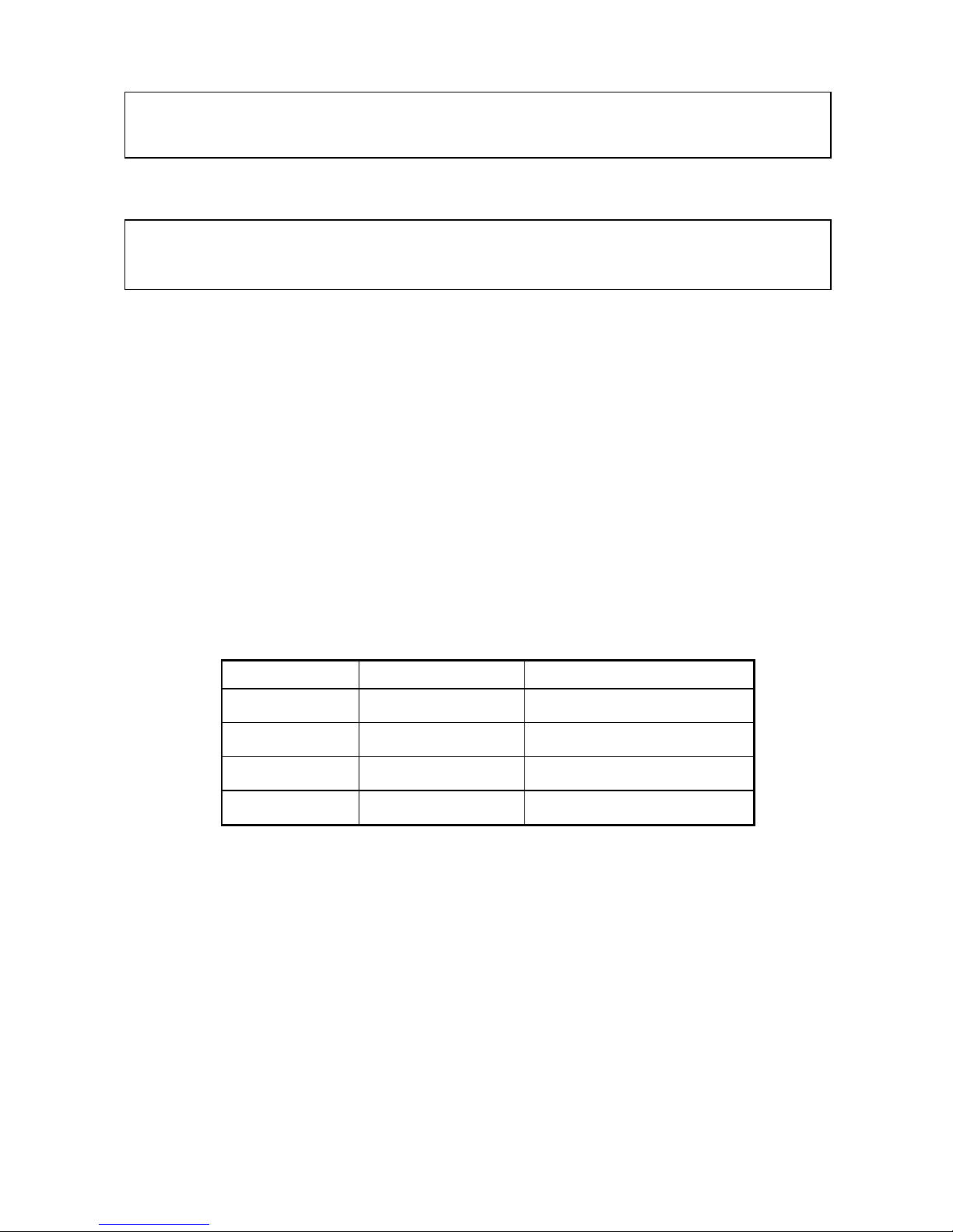
This manual covers the UPS listed as follows. Please confirm whether it is the model you
intend to purchase by performing a visual inspection of the Model No. on the rear panel of the
UPS.
“XL” Model: Long backup time
Model No. Type Model No. Type
1000H 1000HXL
2000H 2000HXL
3000H
Standard
3000HXL
Long backup time
6
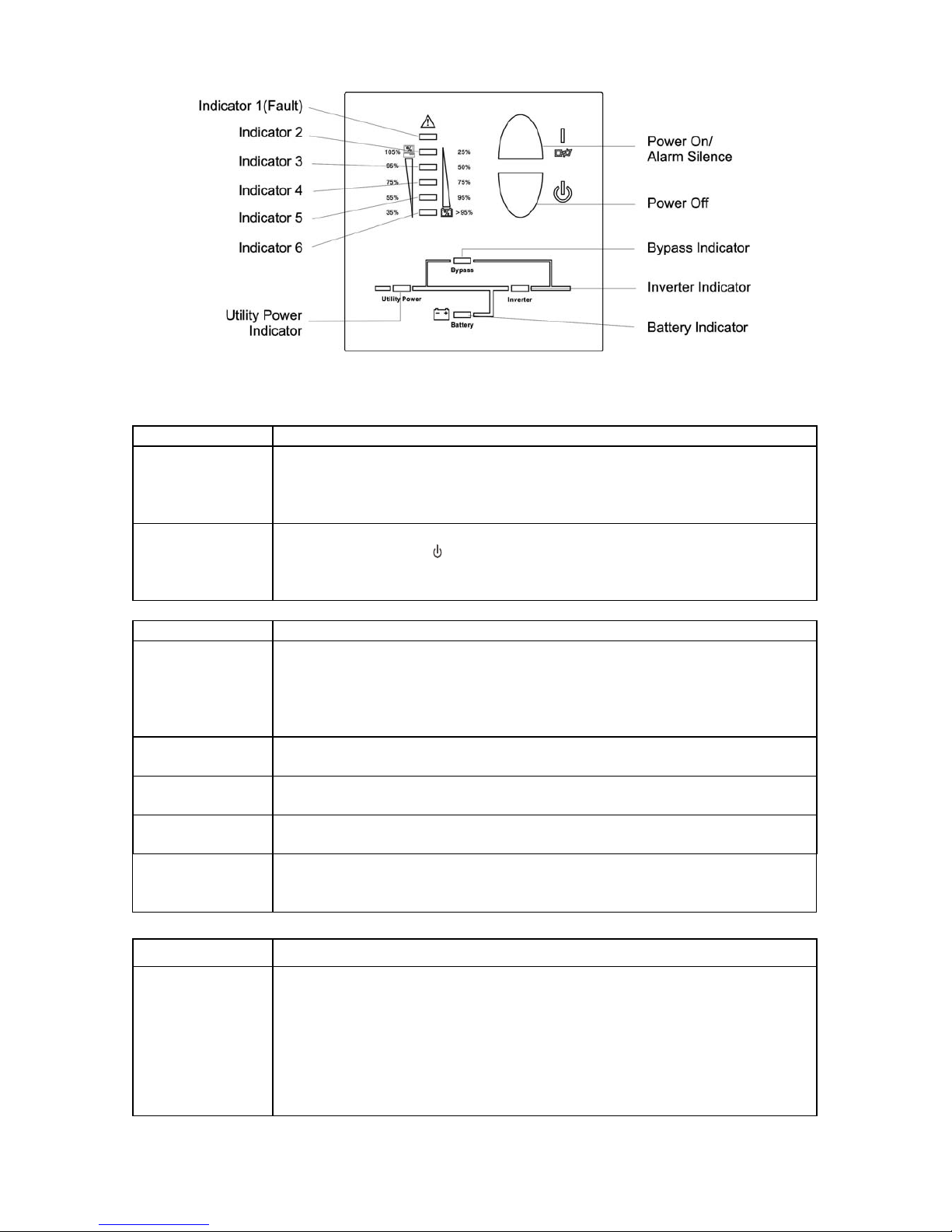
4. System Description
Figure 1: Display Panel
Switch Function
ON - Switch
Turn on UPS system:
By pressing the ON-Switch “I” the UPS system is turned on.
Deactivate acoustic alarm:
By pressing this switch an acoustic alarm can be deactivated.
OFF-Switch
When mains power is normal, the UPS system switches to Standby mode by
pressing OFF-Switch “
“. It is then switched to Bypass and the inverter is off.
At this moment, the output sockets are supplied with voltage via the bypass if
the mains power is available.
Display Function
LINE LED
The green LINE LED lights up if mains voltage is applied to the UPS input.
LINE LED blinks when the phase and neutral conductor have been reversed
at the input of the UPS system.
If LINE LED and BATTERY-LED light up, the mains power supply is out of
tolerance.
BATTERY LED
The orange-coloured BATTERY-LED lights up when the mains power has
failed and the inverter is being powered by the batteries.
BYPASS LED
The orange-coloured BYPASS LED lights up when the UPS system is
supplying voltage provided by the mains power via the bypass.
INVERTER LED
The green-coloured INVERTER LED lights up if the UPS system is supplying
voltage provided by the mains power via the inverter.
FAULT LED
The red FAULT LED lights up and an acoustic warning signal is issued
continuously when the UPS system is in fault condition. Press the Standby
switch in order to turn off the warning tone.
Display Function
LOAD and
BATTERY
CAPACITY LEDs
These LEDs show the load of the UPS system if the mains power is available
(normal operation):
2nd LED: 96%-105% 3rd LED: 71%-95% 4th LED: 51%-70%
5th LED: 31%-50% 6th LED: 0-30%
In the battery operation, the LEDs indicate the capacity of the batteries:
2nd LED: 0-25 % 3rd LED: 26%-50 % 4th LED: 51%-75 %
5th LED: 76%-95 % 6th LED: 96%-100 %
7
5. Connection and Operation
5.1 Connection and operation for 1000H(XL)/ 2000H(XL)/ 3000H(XL)
1) Inspection: Inspect the packaging carton and its contents for damage. Please inform the
transport agency immediately should you find signs of damage.
Please keep the packaging in a safe place for future use.
Note: Please ensure that the incoming feeder is isolated and secured to prevent it
from being switched back on again.
2) Connection:
2.1) UPS Input Connection
If the UPS is connected via the power cord, please use a proper socket with
protection against electric current, and pay attention to the capacity of the socket:
over 10A for 1000H(XL)/2000H, over 16A for 2000HXL/3000H(XL).
2.2) UPS Output Connection
The output of 1000H(XL) and 2000HXL (Non CE) are socket-types only. Simply
plug the load power cord to the output sockets to complete connection.
Model No.
Output Socket (pcs) T erminal Block
1000H(XL) 4 Nil
2000H 6 Nil
2000HXL 4(CE) 6(Non CE) Available(CE) Nil (Non CE)
3000H(XL) 4(CE) 3(Non CE) Available
Besides output sockets, 2000HXL (CE) and 3000H(XL) has the terminal block
available for output as well. The wiring configuration is shown as the following
procedure:
a) Remove the small cover of the terminal block
b) Use AWG14 or 2.1mm2 wires for wiring configuration
c) Upon completion of the wiring configuration, please check whether the wires
are securely affixed.
d) Put the small cover back to the rear panel.
The system may be installed and wired only by qualified electricians in
accordance with applicable safety regulations!
When installing the electrical wiring, please note the nominal amperage of
your incoming feeder
8
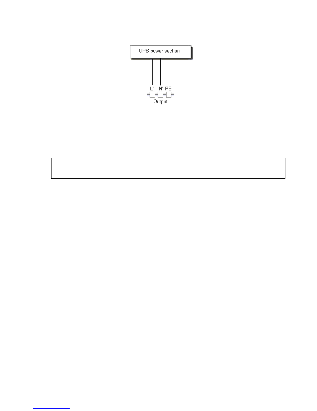
5. Connection and Operation
Figure 2: Connection diagram of 2000HXL(CE) and 3000H(XL)
2.3) Computer Connection:
Connect your computer to the outlet sockets of the UPS system following the above
diagram.
3) Battery Charge: Fully charge the batteries of the UPS system by leaving the UPS system
connected to the mains for 1-2 hours. You may use the UPS system
directly without charging it but the stored energy time may be shorter
than the nominal value specified.
4) Turn On the UPS:
4.1) With utility power connecting:
Press “I” button continuously for more than 1 second to turn on the UPS. Then the
UPS will get into self-test status first. After having finishing the self-test, the UPS
will get into the inverter mode, at this time, the Utility Power LED, Inverter LED, and
Load and Battery Capacity LEDs will light up.
4.2) Without utility power connecting:
Even though utility power is connected to the UPS, the UPS still can be turned on
by just simply pressing “I” button continuously for more than 1 second. Then the
UPS will get into self-test status first. After having finishing the self-test, the UPS
will get into the inverter mode, at this time, Battery LED, Inverter LED, and Load
and Battery Capacity LEDs will light up.
Note: The default setting for bypass mode is no output after UPS is connecting utility
power and breaker is turned on. This can be configured by monitoring software.
5) Test Function:
Test the function of the UPS system by either pressing the On-Switch “I” or disconnecting
the input of the UPS system from the power supply.
Caution!
*Do not connect equipment which would overload the UPS system (e.g. laser printers)

9
5. Connection and Operation
6) Turn Off the UPS:
6.1) In Inverter Mode:
Press “ “ button continuously for more than 1 second to turn off the UPS. Then the
UPS will get into self-test status first. After having finished the self-test, the UPS will
get into bypass mode and the Utility Power LED and Bypass LED will light up. At this
time, the UPS might has output. Disconnect the utility power to turn off the output.
6.2) In Battery Mode:
Press “ “ button continuously for more than 1 second to turn off the UPS. Then the
UPS will get into self-test status first. After having finished the self-test, the UPS will
be turned off completely.
7) Audible Alarm Mute Function: If the alarm is too annoying in battery mode, you may
press “I” button continuously for more than 1 second to clear it. Moreover, the alarm will
be enabled when the battery is low to remind you to shutdown the load soon.
8) Operation Procedure of External Battery for Long Backup time Model (“XL” Model)
The units with CE markings—
(1) Use the battery pack with voltage: 36VDC for 1000HXL (3 pcs of 12V batteries),
96VDC for 2000HXL/3000HXL (8 pcs of 12V batteries). Connection of batteries
more than or less than required will cause abnormality.
(2) One end of the external battery cord is a plug for connecting the UPS and the other
end has a plug for connecting the user battery cabinet
(3) Do not connect the UPS to any load yet. Then, connect the power cord of the UPS to
supply utility power to the UPS to make the UPS operate in utility power mode.
(4) Connect the plug of the external battery cord to the external battery socket on the
rear panel of the UPS to complete the connection procedure and the UPS will start
to charge the battery pack.
The unit without CE markings—
(1) Use the battery pack with voltage: 36Vdc for 1000HXL (3 pcs of 12V batteries), 96Vdc
for 2000HXL/3000HXL (8 pcs of 12V batteries). Connection of batteries more than or
less than required will cause abnormality.
(2) One end of the external battery cord is a plug for connecting the UPS and the other end
has 3 (or 2) open wires for connecting the battery pack.
(3) The battery connection procedure is very important. Any incompliance may result in the
risk of electric shock. Therefore, the following steps must be strictly complied with.
(4) First connect in series the batteries of the pack to ensure proper battery voltage.
(5) Connect the external battery cord to the battery terminal (DO NOT connect the battery
socket of the UPS first. Otherwise, it may cause electric shock). Connect the red wire
to.
 Loading...