


European Audio Team
INSTRUCTIONS FOR USE
F-Note Tonearm

2
Dear Music Lover,
!
Congratulations and thank you for choosing European Audio Team products.
Your E.A.T. F-Note tonearm has been handcrafted and rigorously tested by skilled technicians
at the European Audio Team factory to give you years of enjoyable, trouble free service.
Although it may seem like asking for driving directions, please take a few moments
to read all of this manual. It has many helpful tips and ideas on properly setting up
and using your system. We promise that if you take the time to read and follow these
tips you’ll get better system performance and enjoyment. Please contact your dealer if
you require additional assistance.
F-Note tonearm incorporates an array of features that contribute to its audiophile
performance:
1. Hand polished aluminium finish
2. 2 Stage VTA adjustment
3. Laser VTA control
4. Laser Azimuth control
5. Damped counterweight
6. Excentric gimbal bearing system
7. Pre-adjusted anti-skating system
8. Hardened and polished bearing cones
Throughout the manual, this symbol will alert you to potential hazards for the user or the unit,
and how to avoid possible misuse.

3
Contents
Product illustrations and key 4-5
Setup
1. EAT Forte / Forte S installation
a) Dissassembling of standard EAT flange 8
b) Assembling EAT F-Note with own flange 9
2. Tonearm setting 8
c) VTA adjustment 8-9
d) Azimuth adjustment 9
e) Cartridge installation 9-10
f) Counterweight installation, Vertical Tracking Force setting (VTF) 10
g) Tonearm output connection 10-11
h) Anti-skating adjustment 11-12
3. Laser VTA and Azimuth control 12
Technical specifications 14
Troubleshooting, warranty, service 15

4

5
KEY: CONTROLS, FEATURES AND CONNECTIONS
1. Headshell with ½‘‘ mount
2. Tonearm tube
3. Tonearm rest position
4. Laser technology
5. Fine VTA adjustment
6. Damped counterweight
7. Tonearm lift lever
8. Spirit level
9. VTA locking screw
10. EAT Forte / Forte S mounting flange
11. Anti-skating transport screw
12. Anti-skating mechanism with weight

6
SETUP
1. EAT FORTE / FORTE S INSTALLATION
a) Dissassembling of standard EAT flange
Carefully remove the platter from the bearing shaft and put it on the safe place. Turn the
turntable on the side so that the screws which holds standard tonearm flange can be reached.
Remove 4 screws (M6 x 55) from the bottom as shown in the followint illustration.
b) Assembling EAT F-Note with own flange
Place the F-Note tonearm with new own flange over the hole in the chassis. By using longer
screws (recommended screw are M6 x 70), tighten the new flange on the chassis.

7
2. TONEARM SETTING
a) VTA adjustment
To set the Vertical Tracking Angle, first put a record on the platter. When the needle is lowered
into the record groove, the tube of the tonearm should be parallel to the surface of the record.
If it is not, loosen both hexagonal screws in the tonearm base just enough to allow vertical
movement of the arm pillar without force, and slide the arm up or down until it is parallel.
Carefully and evenly retighten the hexagon screws without applying excessive force (which
could deform the arm pillar).
F-Note tonearm has two stage VTA adjustment. Once you set VTA by moving main tonearm
pillar up and down, you can unlock fine adjustment with locking screw shown on following
illustration.
With needle in the record groove, carefully move tonearm up or down with main VTA
adjustment crew. When you are satisfied with VTA setting, carefully retighten VTA locking
screw and move tonearm to the tonearm rest position.

8
b)
!
Azimuth adjustment
The cartridge needle must be perpendicular to the record in order to trace the groove wall
modulations correctly.
The azimuth (angle) is precisely set by the factory. In the event that you need to modify this
setting, however, follow the instructions below.
Loosen the small AZIMUTH SET SCREW, again using the 1.5 mm hexagonal key.
DO NOT REMOVE THE AZIMUTH SET SCREW COMPLETELY!
Loosen the screw just enough to be able to gently rotate the arm tube and set the azimuth to
the correct position. The correct position can be checked from the front view, preferably with
the needle placed on a mirror placed on the platter. Once the azimuth setting is correct, gently
re-tighten the AZIMUTH SETTING SCREW.
Examples of incorrect azimuth setup:
Too much left angle:
The correct position is 100% perpendicular to the record.
Too much right angle:
9
c) Cartridge installation
Install the cartridge into the aluminium headshell, using the appropriate hardware included
with your cartridge.
Connect the cartridge as indicated below:
• White left channel L+
• Red right channel R+
• Green right channel R-
• Blue left channel L-
For correct cartridge alignment, use the two-point cartridge alignment protractor provided with
your F-Note accessories. If unfamiliar with two-point setup, please refer to your dealer.
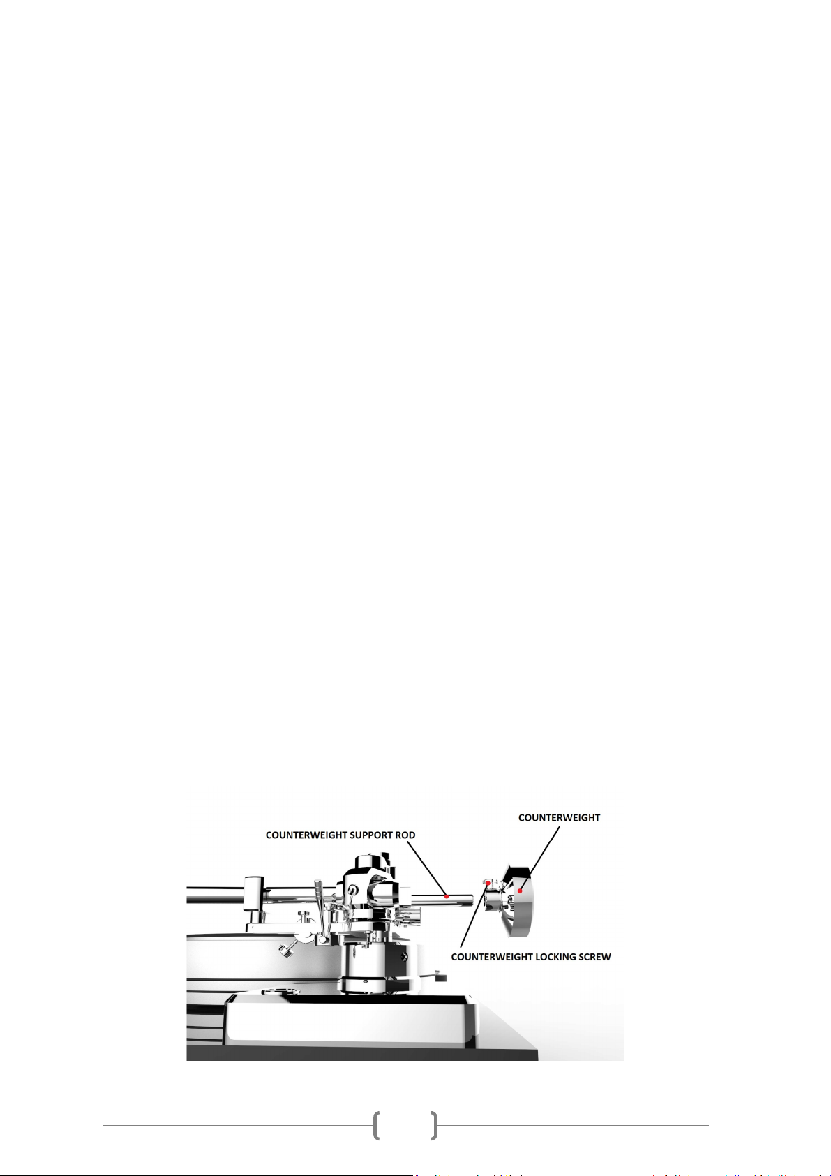
d) Counterweight setting, Vertical Tracking Force setting (VTF)
The counterweight supplied is suitable for cartridges weighing between 7 - 22g.
Place the counterweight onto the rear end of the counterweight support rod, so that the
locking screw shows towards the front of the player. Lower the tonearm lift and position the
cartridge in the space between tonearm rest and platter. Carefully move the counterweight
until the tonearm tube balances out. The arm should return to the balanced position if it is
moved up or down. This adjustment must be done carefully. Do not forget to remove the
cartridge protection cap if fitted.
Once the arm is correctly balanced return it to the tonearm rest.
Move the counterweight towards (seen from the front) to adjust the downforce according to the
cartridge manufacturer's recommendations. Once you set recommended downforce, tighten
locking screw to secure the counterweight position. Fine downforce can be adjusted by rotating
main counterweight body on fine thread.

10
Please note: Adjust the downforce prior to installing the anti-skating weight.
e) Tonearm output connection
Connect the tonearm cable provided with the accessories to the 5-PIN tonearm output that
is located at the rear of the tonearm, behind the main body.
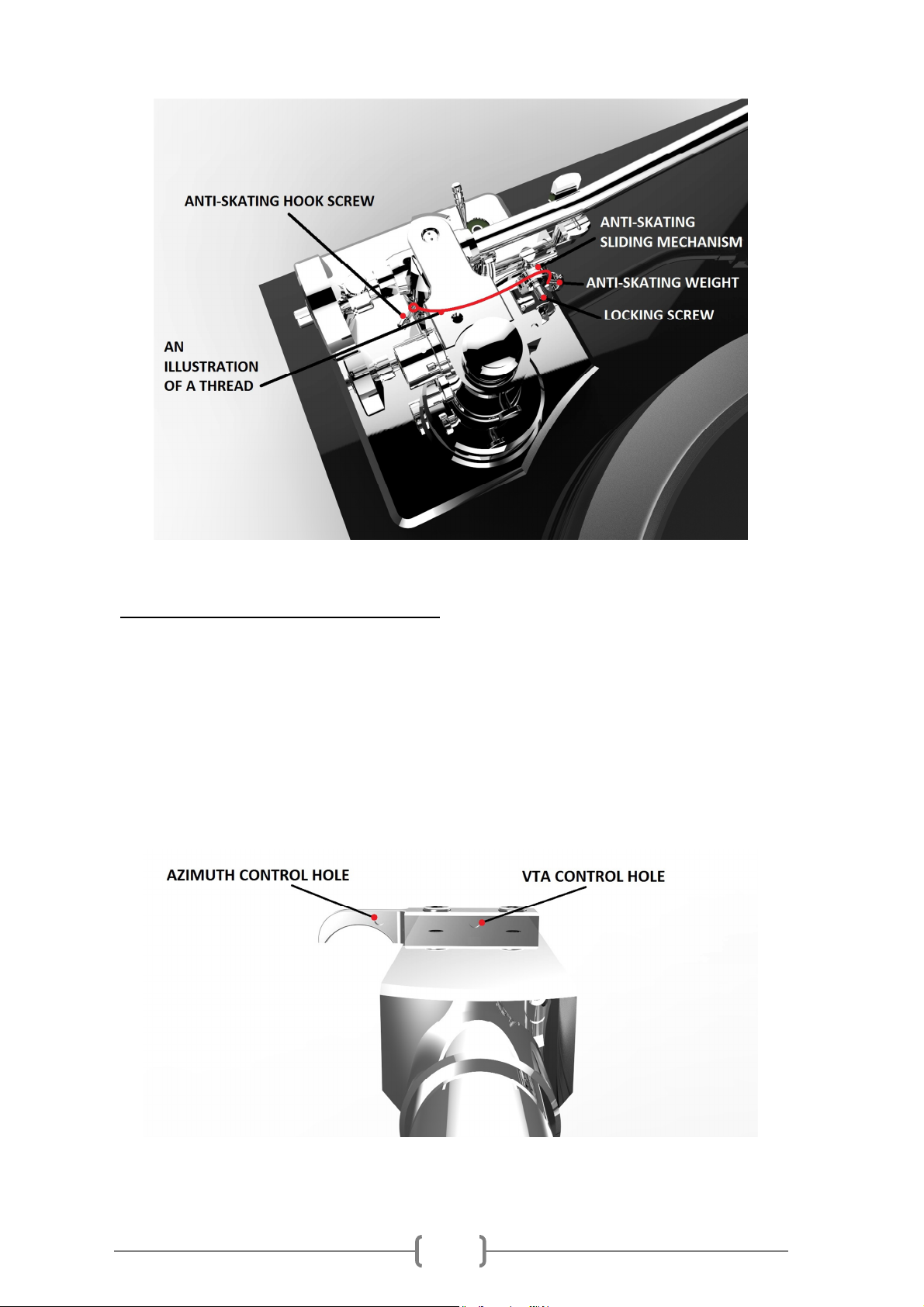
f) Anti-skating adjustment
Anti-skyting system supplied with F-Note tonearm is pre-adjusted from the factory and it’s very
easy to use.
Anti-skating thread is already fixed by anti-skating hook screw in the tonearm body. Antiskating sliding mechanism is also pre-mounted and fixed by locking screws.
For correct anti-skating use, please unlock the sliding mechanism and set requested anti-skating
force which must be corresponding to the downforce as follows:
Downforce Anti-skating groove
10 - 14mN 1st groove from bearing
15 - 19mN 2nd " " "
20mN and bigger
3rd " " "
11
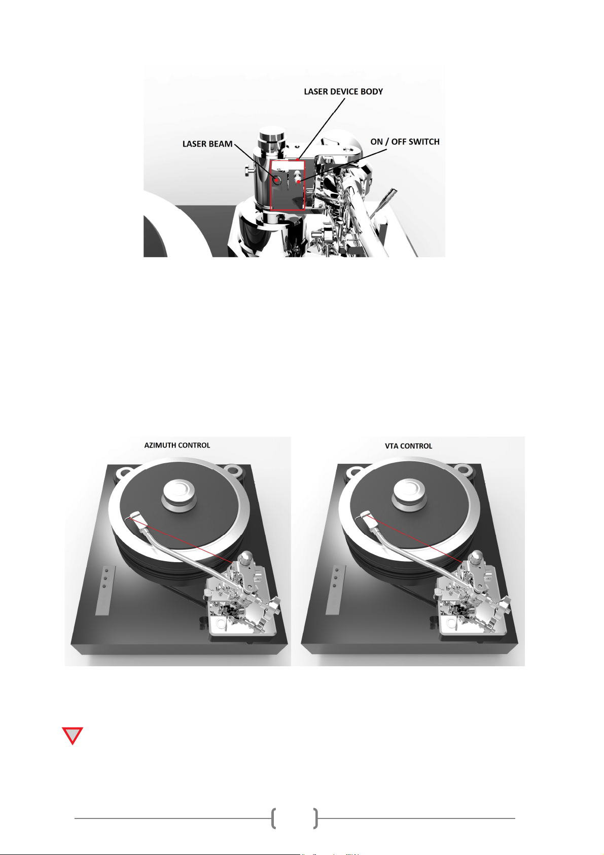
3.
LASER VTA AND AZIMUTH CONTROL
F-Note tonearm has an unique laser technology for final control of your VTA and Azimuth
setting.
F-Note headshell has two small holes (looking from the back of the headshell).
Left hole located in the fingerlift is for Azimuth control.
Right hole in the middle of headshell is for VTA control.
12
!
Turn ON laser beam by turning ON / OFF switch clockwise. Once laser beam is ON, place
cartridge in LP groove.
If your Azimuth is correct, the laser beam will shine in the middle of Azimuth control hole. If you
do not see laser beam, please go back to Azimuth adjustment (page 8).
If your VTA is correct, the laser beam will shine in the middle of VTA hole. If you do not see
laser beam, please go back to VTA adjustment (page 7).
Please be sure to turn off the laser device after testing.

13
Technical data EAT F-Note tonearm (12’’):
Bearing type: Gimbal bearings
Effective length: 304.8mm
Effective mass: 21.4g
Pivot to spindle distance: 291.6mm
Overhang: 13.2mm
Offset angle: 18°
Max. null point: 125mm
Min. null point: 251.7mm

14
Troubleshooting
No signal through one or both channels:
• No signal contact from the cartridge to the internal tonearm wiring; or from that to the arm lead; or
from that to the phono box; or between that and the amplifier. This could be due to a faulty plug,
broken wire or loose solder joint in the plug/socket connection.
• Phono input not selected at amplifier.
• Amplifier not switched on.
• Amplifier or speakers are defective or muted.
• No connection to the loudspeakers.
Strong hum on phono input:
• No ground connection from cartridge or arm or arm cable to amplifier, or ground loop.
Distorted or inconsistent sound from one or both channels:
• Tonearm output is connected to wrong input of amplifier, or MM/MC switch is incorrectly set.
Needle or cantilever damaged.
Service
Should you encounter a problem that you are not able to identify or alleviate despite the above
information, please contact your dealer for further advice. Only when the problem cannot be resolved
should the unit be sent to the responsible distributor in your country.
Guarantee repairs will only be effective if the unit is returned in appropriate packaging. For this reason
we recommend keeping the original packaging.
Warranty
The manufacturer accepts no responsibility for damage caused by failing to adhere to these instructions
for use and/or by transportation without the original packaging. Modification or change to any part of
the product by unauthorized persons releases the manufacturer from any liability over and above the
lawful rights of the customer.
The information above was correct at the time of going to press. The manufacturer reserves the right to make
changes to the technical specifications without prior notice as deemed necessary to uphold the ongoing process of
technical development.
E.A.T. European Audio Team is a Registered Trademark of Jozefina Lichtenegger.
This guide was produced by: E.A.T. European Audio Team. Copyright © 2019. All rights reserved.
 Loading...