

Easy Track RB1460 Installation Instructions Manual
EASY TRACK
™
4' to 8' Tow er C loset
PLEASE READ INSTALLATION INSTRUCTIONS
BEFORE ASSEMBLING.
IF YOU ARE MISSING PARTS OR HAVE QUESTIONS
PLEASE CALL OUR
CUSTOMER HELP LINE:
R B 1460
1(800)562-4257
Visit Our Web Site For Design Ideas and Frequently Asked Questions.
www.windquestco.com
8 AM TO 5 PM EST
Monday - Friday
IMPORTANT:
TRACK must be screwed into studs behind wallboard. Warranty is void if TRACK is
only screwed into drywall, as TRACK will fall down when screws pull out of drywall.
Tools R equired:
12'
Tape M easure
B a tte ry o r E le c tric D rill
w ith N o . 2 P h illip s , 1 /8 ",
and 1/2" D rill B its
Level
H acksaw
H and or E lectric S aw
(if you need to cut shelves)
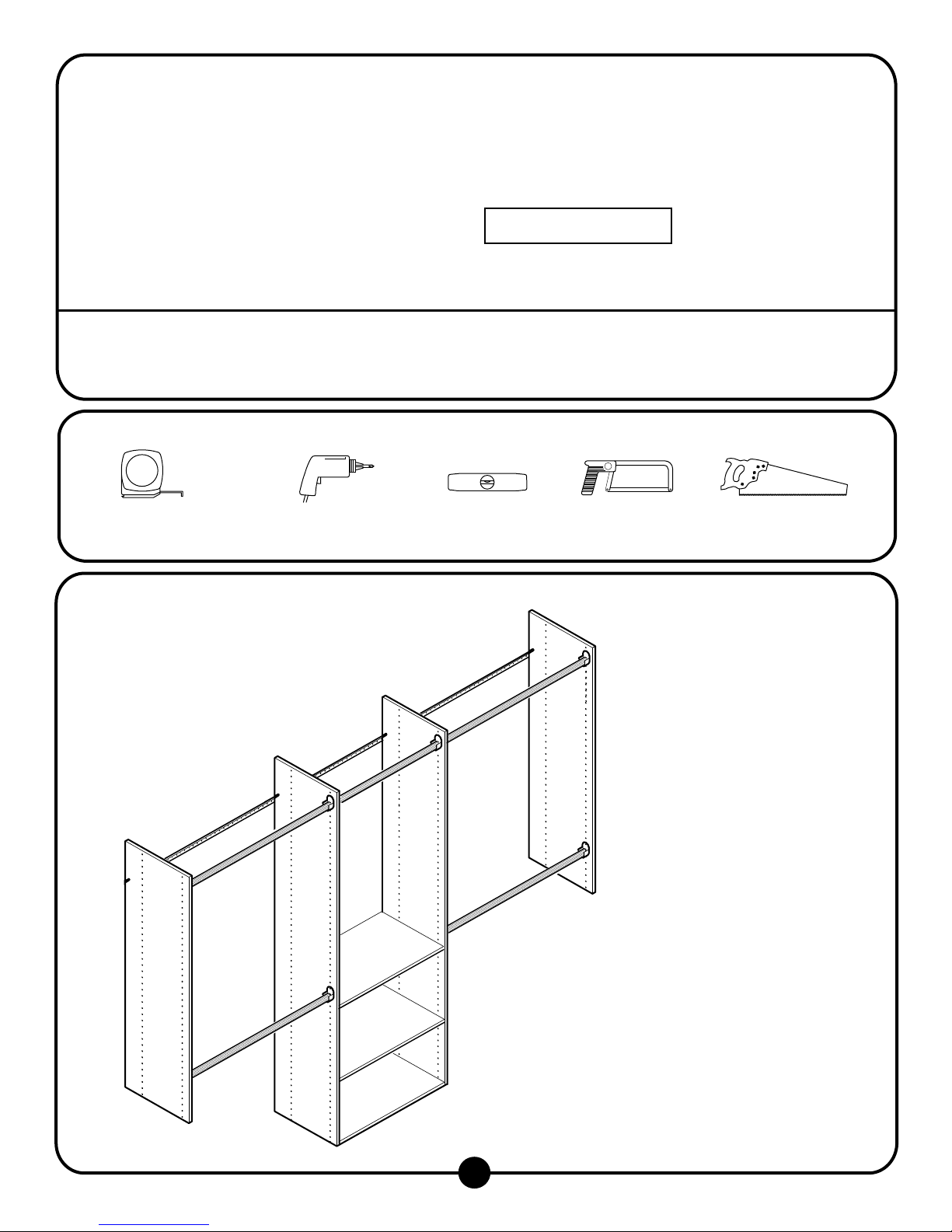
M odel R B 1460 Includes:
2 - 7 2 " V e rtic a l P a n e ls
2 - 4 8 " V e rtic a l P a n e ls
3 - 2 3 7 /8 " S h e lv e s
4 - 3 4 5 /8 " W a rd ro b e R o d s
1 - 2 3 7 /8 " W a rd ro b e R o d s
1 - 2 3 7 /8 " S u p p o rt C le a t
10 - R od H olders
18 - #8 x 50 m m S crew s
1 8 - W h ite S c re w C o v e rs
8 - S helf P ins
8 - # 6 x 1 /2 " Z in c S c re w s
4 - Toggle Bolts w ith S crew s
2 - 48" E A S Y TR A C K
1
R em ove E xisting S helving
1
R em ove existing closet rod, shelf, and shelf support.
If, d e s ire d , fill h o le s in p la s te r a n d re p a in t c lo s e t.
W h e n fillin g h o le s , m a rk th e s e lo c a tio n s , a s th e y
generally m ark the location of studs.
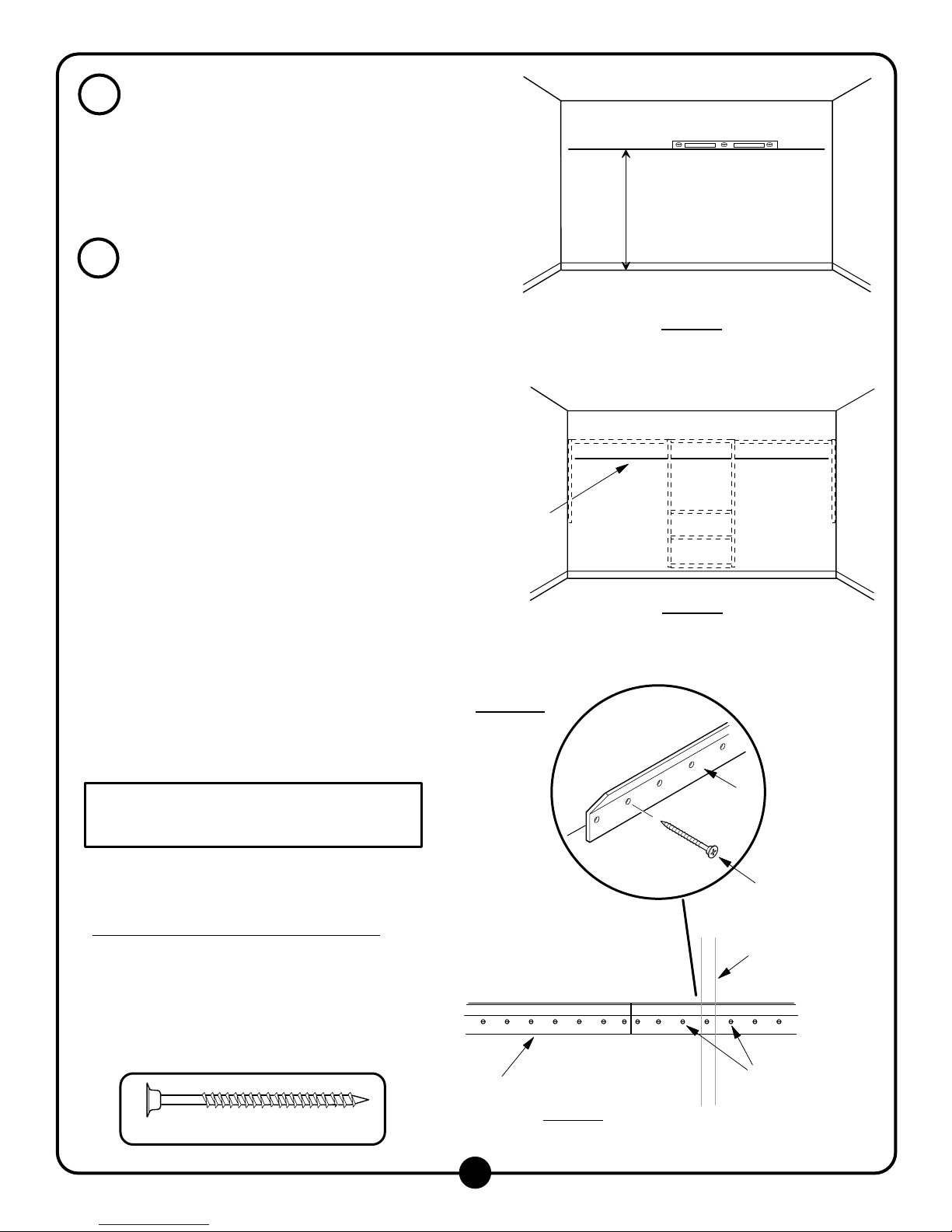
2
A ttach Track
U sing a level, draw a line across the back of the
c lo s e t, 7 6 " a b o v e flo o r. The 76" height w ill put the top
of the verticals 84" above the floor, and provide 41"
for double hanging clothes. The track height can be
adjusted depending on the individual needs.
Figure 1.
L o c a te s tu d s . If th e s tu d s a re n o t m a rk e d fro m S te p 1 ,
tap w all or use an electronic stud finder to locate
s tu d s . M a rk w a ll 1 /2 " b e lo w h o riz o n ta l lin e . S tu d s
(2 x 4) are usually located on 16" centers m easured
fro m th e le ft o r rig h t s id e .
Level line 76"
fro m th e flo o r,
then m ark stud
locations
Figure 1
Lay out closet design to determ ine approxim ately
w here vertical panels w ill be located. S ee Figure 7
o n p a g e 5 fo r d im e n s io n s . M a r k th e v e rtic a l p a n e l
lo c a tio n s o n th e w a ll b e lo w th e h o riz o n ta l lin e .
Figure 2.
If a n y o f th e v e rtic a l p a n e ls a re n o t w ith in 3 " o f a s tu d , a
to g g le b o lt is n e e d e d to a tta c h th e tr a c k to th e w a ll. T o
d e te rm in e th e lo c a tio n o f th e to g g le b o lt(s ), h o ld o n e o f
th e tra c k s o v e r th e lin e , tig h t to th e c o rn e r. M a rk th e
hole locations near the studs and vertical panels
(keeping track level).
NO TE: D o not use the holes directly behind the
vertical panels, use the holes one space aw ay,
especially in corners.
NO TE: If toggle bolts are required they m ust be
in s ta lle d p r io r to a tta c h in g th e tr a c k to th e w a ll.
R e fe r to p a g e 3 .
M easure the rem aining closet w idth. M ark and cut the
re m a in in g tra c k to le n g th w ith a h a c k s a w . M a rk th e
holes near the vertical panels.
For S tandard D ryw all/W allboard/S heetrock:
For holes m arked at studs
d rill b it. A tta c h th e tra c k to w a ll u s in g th e # 8 x 5 0 m m
screw s.
the track unsupported, it m ust be attached to the
w a ll.
Figure 3a
F ig u r e 3 .
, d rill a p ilo t h o le w ith a 1 /8 "
.
N O T E : D o n o t le a v e t h e e n d o f
M ark vertical panel
locations - see Figure
7 on page 5 for
dim ensions
Figure 2
Figure 3a
Track
#8 x 50m m S crew
Vertical P anel
Location
#8 x 50m m Screw
2
Track
Figure 3
M ark holes around
vertical panel for
e ith e r a s tu d o r a
toggle bolt
 Loading...