

Page 1

easyRAID Q12
Hardware User Manual
Ultra 320 SCSI to Serial ATA
&
Fibre Channel to Serial ATA
Disk Array Systems
Version 1.0
Page 2
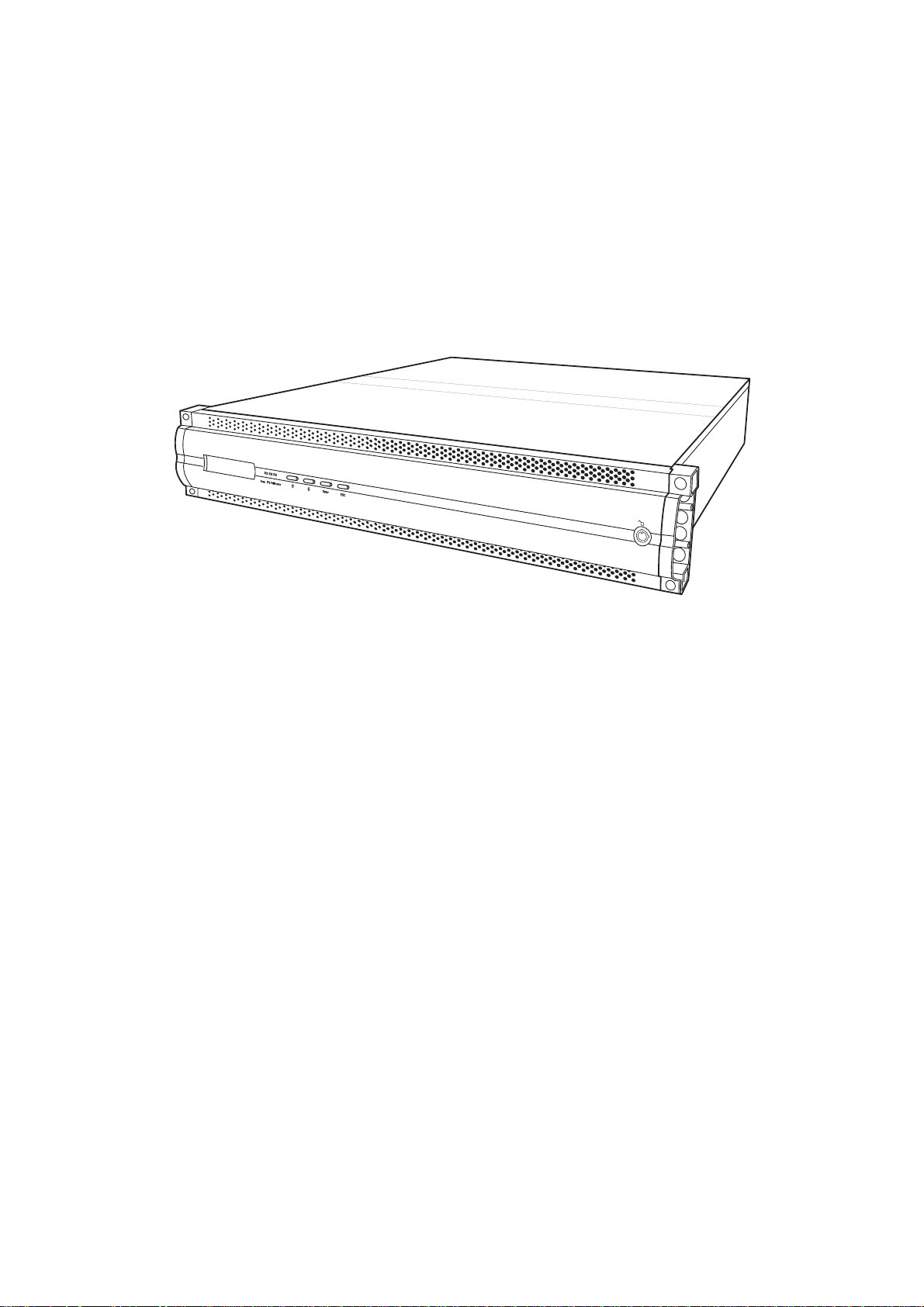
easyRAID Q12-U4R2
Ultra 320 SCSI to Serial ATA
Disk Array System
&
easyRAID
Fibre Channel to Serial ATA
Disk Array System
Q12-F2R2
Hardware User Manual
Page 3

Page 4

Table of Contents
Preface................................................................................................................... i
Chapter 1 Overview
Features ................................................................................................................2
Understanding RAID .............................................................................................3
NRAID ..............................................................................................................3
Just a Bunch Of Disks ......................................................................................3
RAID Levels .....................................................................................................3
Hot Spare Disks ...............................................................................................6
RAID Combinations ..........................................................................................6
Summary of RAID Levels .................................................................................7
System Requirements ...........................................................................................8
Operating Environment ....................................................................................8
VT100 Terminal Settings ..................................................................................8
Host Interface ...................................................................................................9
Hard Disks ........................................................................................................ 9
Chapter 2 Basic Configuration
Unpacking ........................................................................................................... 11
Components ........................................................................................................12
Closed Front Panel .........................................................................................12
Open Front Panel ...........................................................................................13
Disk Tray ........................................................................................................14
ERQ12-U4R2 Rear View ................................................................................15
ERQ12-F2R2 Rear View ................................................................................16
Installing Disks ....................................................................................................17
Making Connections ...........................................................................................19
Connecting the Host Interface ........................................................................19
Connecting a network .....................................................................................21
Connecting and Turning on the Power ...........................................................22
Mounting in a Rack .............................................................................................23
Installing the Rail Extenders ...........................................................................24
Chapter 3 Maintenance
Replacing a Disk .................................................................................................25
Replacing a Power Supply ..................................................................................26
Upgrading Memory .............................................................................................28
Appendix
Hardware Specifications .....................................................................................31
i
Page 5

Page 6
Preface
About this Manual
This manual is designed to make the disk array system as easy to use as possible. Information
contained in this document has been checked for accuracy , but no guarantee is given that the contents are correct. Information and specifications are subject to change without notice.
Conventions
Caution
This symbol is used to remind users to pay attention to important
descriptions regarding usage and maintenance (repair) or additional
important information related to this disk array system.
Note
This symbol is used to remind users of useful information that can make
procedures such as configuration easier to accomplish.
i
Page 7
ERQ12-U4R2 & ERQ12-F2R2 Serial ATA Disk Array Systems
Important Safety Instructions, Care and Handling
Preface – Important Safety Instructions, Care and Handling
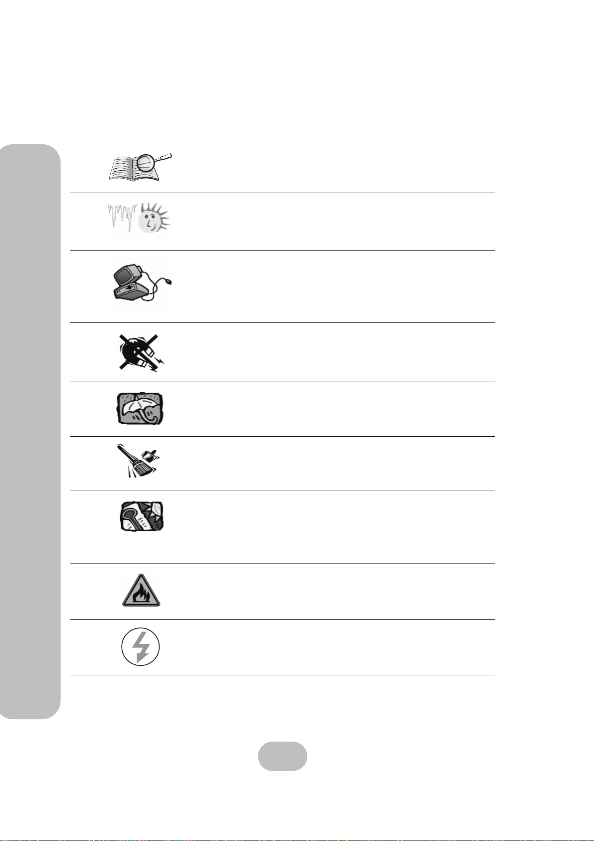
Before starting, take a few minutes to read this manual.
Read all of these instructions and save this manual for
later reference.
Protect the disk array system from extremely high or low
temperatures. Let the disk array system warm (or cool)
to room temperature before using it.
Protect the disk array system from being bumped or
dropped. Do not place the disk array system on an
unstable cart, stand, or table. It may fall, causing serious
damage to the product.
Keep the disk array system away from magnetic forces.
Do not use the disk array system near water.
V
Keep the disk array system away from dust, sand, or dirt.
Gaps and openings in the cabinet are provided for ventilation. Never block or cover these openings, because
the disk array system may overheat and become unreliable. Don’t place the disk array system on a bed, sofa,
rug, or other similar surface.
Do not place the disk array system near or over a radiator or other heat source.
Refer to the rating plate for the correct voltage and
ensure that the appliance voltage corresponds to the
supply voltage.
ii
Page 8
ERQ12-U4R2 & ERQ12-F2R2 Serial ATA Disk Array Systems
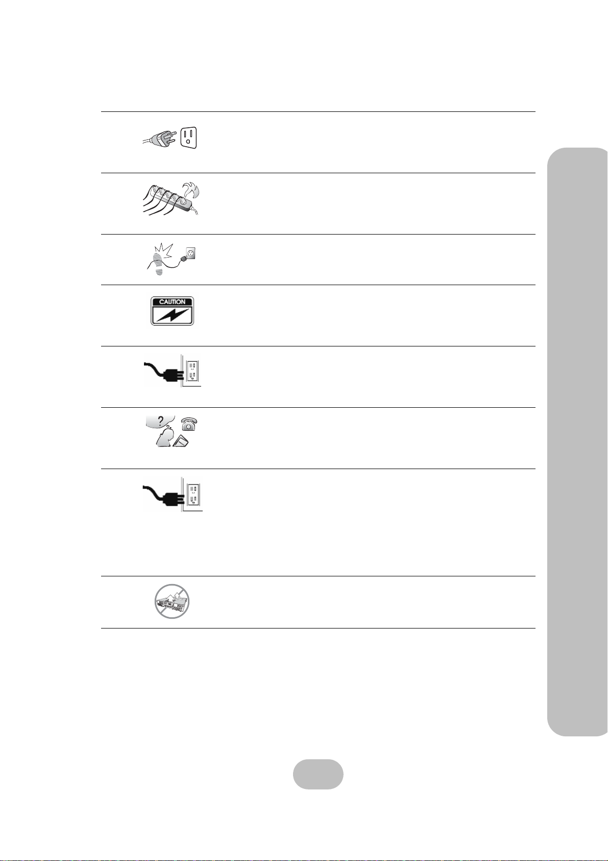
The appliance must be grounded. The disk array system
is equipped with a 3-wire grounded type of power cord.
This power cord will only fit into a grounded type of
power outlet.
If an extension cord or a power center is used with the
disk array system, make sure that the total current consumption of all products plugged into the wall outlet
does not exceed the ampere rating.
Do not place the disk array system where the cord will
be walked on.
Never push any kind of object into the disk array system
through cabinet gaps and openings, since they may
touch dangerous voltage points and cause a risk of fire
or electric shock.
Unplug the power cord from the wall outlet before cleaning. Keep the disk array system dry. Do not use liquid
cleaners, aerosol cleaners, or a wet cloth. Use a damp
cloth for cleaning.
Preface – Important Safety Instructions, Care and Handling
Except as specifically explained in this User Manual, do
not attempt to service the disk array system by yourself.
Opening or removing the covers may expose you to
dangerous voltages.
Unplug this product from the wall outlet and refer servicing to qualified service personnel under the following
conditions.
• If the disk array system has been exposed to
water or any liquid.
• If the disk array system has been dropped or the
cabinet damaged.
Users should not remove the cover.
o
GGw
GGY
F
a
n
1
P
o
w
e
r
1
iii
Page 9
ERQ12-U4R2 & ERQ12-F2R2 Serial ATA Disk Array Systems
Placement Notes
Preface – Important Safety Instructions, Care and Handling
• The disk array system LCD panel can be damaged by exposure to
direct sunlight. Limit exposure to subdued or indirect sunlight only.
• The disk array system should be used only in clean environments
that are free from airborne contaminants such as dust, dirt, and
smoke. Excessive moisture or oil particles in the air can also hinder
disk array system performance.
• To reduce the possibility of data errors caused by electromagnetic
interference, locate the disk array system at least five feet away
from electrical appliances and equipment that generates magnetic
fields.
Power Supply Safety Notes
• To avoid electric shocks, do not use an extended power cord or an
outlet that does not match the disk array system plug or leaves the
plug exposed.
• The disk array system has a 3-wire grounded plug. The third pin
connects to ground; do not remove it.
• If the power cord or plug is damaged or worn, unplug it immediately
and contact a qualified service technician for maintenance.
• To avoid fire or electric shocks, do not overload electric power outlets.
iv
Page 10
1 Overview
The disk array system uses groups of inexpensive disks to provide flexibility when
balancing data availability, access rate, and
capacity management needs.
High data availability is achieved by using
the fault tolerance features of RAID
(Redundant Array of Inexpensive Disks);
hot spare disks with automatic on-line
rebuild; hot swap disks, and power supplies;
independent SATA disk controllers; and
dual host controllers. Our confidence in the
disk array system is backed by a three year
warranty.
A high data access rate is achieved by combining the individual data rates of SATA disks in a
RAID configuration. SATA disks lack some of the features of SCSI disks but are just as fast
when used with a high performance RAID controller. In the disk array system, RAID is controlled by a high performance CPU, which transfers data through dual host interfaces at the maximum possible rate.
Flexible data capacity management is achieved with on-line RAID expansion, RAID capacity
division into slices, and multiple logical RAIDs. Management is performed through front panel,
RJ-45, or RS-232 interfaces.
1
Page 11

ERQ12-U4R2 & ERQ12-F2R2 Serial ATA Disk Array Systems
Features
1 Overview – Features
The main features of the disk array system are listed as follows. Refer to the specifications table
on page 31 for more detailed information.
• Operating system independent
• NRAID, JBOD, RAID 0, 1, 3, 5, 0+1, 30, or 50 array grou ps
• On-line expansion
• Allows division of array groups into slices, each mapped to a LUN
• Hot spare disk and automatic on-line rebuild
• Two hot swap power supplies – if one fails, the others take over without interruption
• Twelve SATA channels
• Fast 64-bit RISC CPU based RAID controller with up to 1 GB of DDR cache memory.
• Dual Ultra SCSI (ERQ12-U4R2) or fibre channel (ERQ12-F2R2) host interfaces
• Audible alarm, disk tray LED, and LCD panel failure indicators
• Configuration via the front panel or RS-232 interfaces
2
Page 12
ERQ12-U4R2 & ERQ12-F2R2 Serial ATA Disk Array Systems
Understanding RAID
Read this section to understand how to balance data availability, access rate, and capacity management needs.
NRAID
NRAID (Non-RAID) is an array that concatenates the space of all hard disks linearly and forms a
large, logical disk. The space presented by the NRAID array starts sequentially from the space of
the first member disk to the last member disk without striping, mirroring, or parity.
Just a Bunch Of Disks
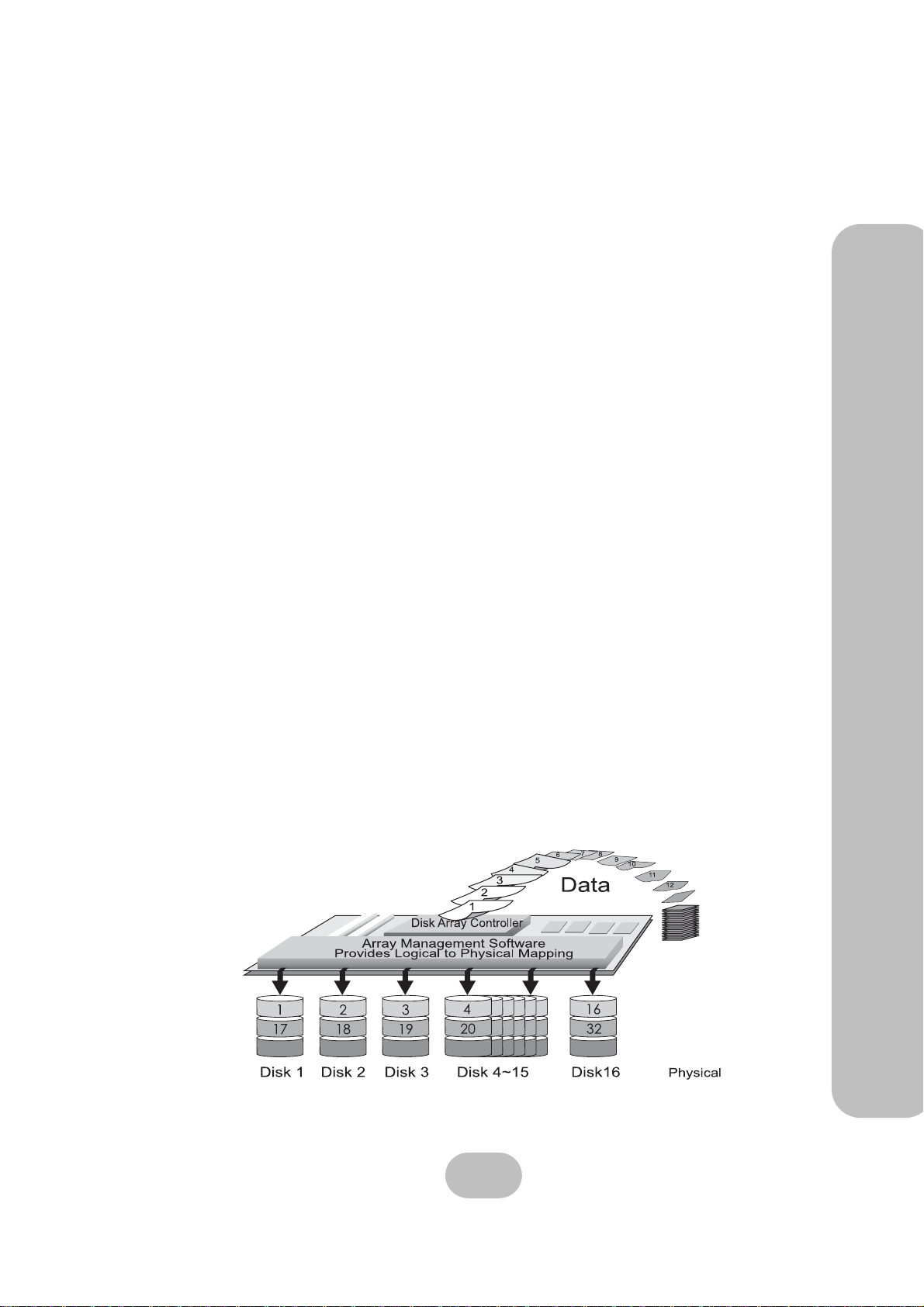
Just a Bunch Of Disks (JBOD) consists of two or more disks that can be different sizes. Disk 1 is
completely filled, then disk 2, disk 3, and so on until the final disk is full.
The total capacity of JBOD is the sum of the capacities of each disk. Disks are added until the
desired total capacity is reached.
JBOD is used in the following situations:
• Building useful capacity from disks that are too small to be individually useful
• Making capacity management easier, since the user only sees one logical disk
JBOD doesn’t improve data availability or access rate when compared with a single disk.
1 Overview – Understanding RAID
RAID Levels
The overall arrangement of disks in RAID is called the RAID level. Read this section to understand RAID levels.
RAID 0
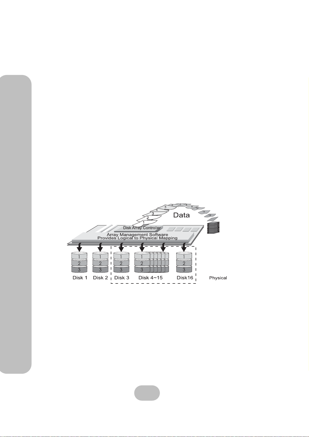
In RAID 0, data is divided into pieces and written to all disks in parallel. This process is called
striping because the pieces of data form a stripe across multiple disks. This improves access rate,
3
Page 13
ERQ12-U4R2 & ERQ12-F2R2 Serial ATA Disk Array Systems
but makes availability lower, since there are more disks and failure of a single disk causes failure
of the array. A RAID 0 array is unsuitable for data that can not easily be reproduced, or for data
that must be available for critical system operation.
1 Overview – Understanding RAID
RAID 0 consists of two or more disks of equal capacity. The total capacity of RAID 0 is the sum
of the capacities of each disk. Disks are added until the desired total capacity is reached.
A RAID 0 array is useful in the following situations:
• Storing program image libraries or run-time libraries for rapid loading. A backup exists
because these libraries are usually supplied on read-only media.
• Storing large tables or other structures of read-only data for rapid application access. This
data should be backed up so that it can be recreated in the event of a failure.
• Capturing data from external sources at very high data transfer rates.
A RAID 0 array is not useful in the following situations:
• Applications that make sequential requests for small amounts of data. These applications
spend most of their I/O time waiting for disks to spin, whether or not they use striped
arrays.
• Applications that make synchronous random requests for small amounts of data.
RAID 1
Optional
In RAID 1, data is duplicated on two or more disks to provide high access rate and very high data
availability. This process is called mirroring. If a disk fails, the RAID controller directs all
requests to the surviving members.
A RAID 1 array is useful in the following situations:
• Availability requirements are very high
• High access rate is required
• Cost of storage is a secondary issue
4
Page 14
ERQ12-U4R2 & ERQ12-F2R2 Serial ATA Disk Array Systems
RAID 3
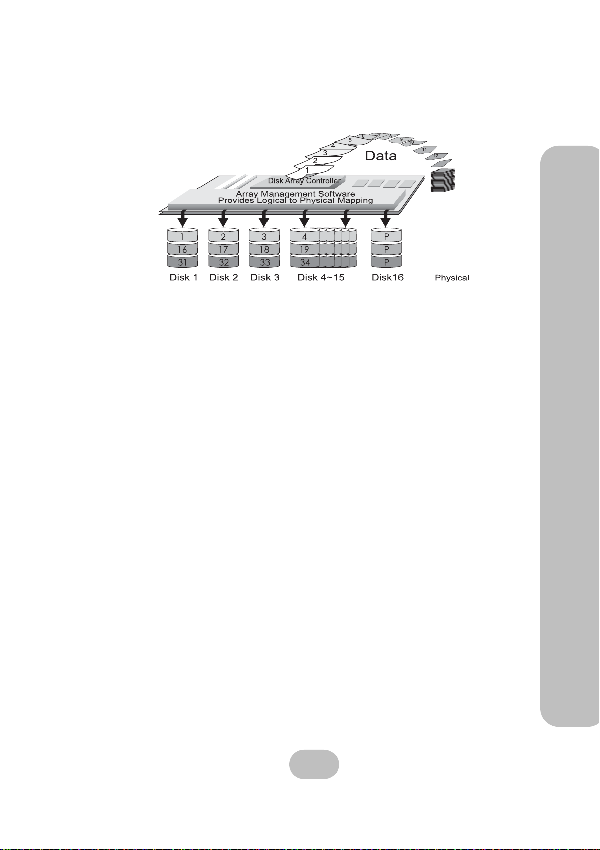
In RAID 3, data is divided into pieces; the parity of these pieces is calculated; and the pieces are
written to separate disks in parallel with the writing of the parity to a dedicated disk. This process
is called striping with parity . The parity disk stores redundant information about the data on other
disks. If a single disk fails, then the data on the other disks is used to regenerate the data on the
failed disk. Striping delivers a high access rate and parity delivers good data availability. The single parity disk is a bottleneck on sequential writes, since parity must always be written to the single parity disk.
1 Overview – Understanding RAID
RAID 3 consists of two or more disks used for data and one disk used for fault tolerant data. The
total capacity of RAID 3 is the sum of the capacities of each data disk. Add disks until the desired
capacity is reached, then add one more disk for fault tolerance.
RAID 3 is used by the following applications that request large amounts of data sequentially:
• Processing of graphical or video images
• Processing of CAD/CAM files
RAID 3 has the following distinctive features:
• Excellent performance for data transfer characteristics
• Not well suited for transaction processing or other I/O request intensive applications
5
Page 15
1 Overview – Understanding RAID
ERQ12-U4R2 & ERQ12-F2R2 Serial ATA Disk Array Systems
RAID 5
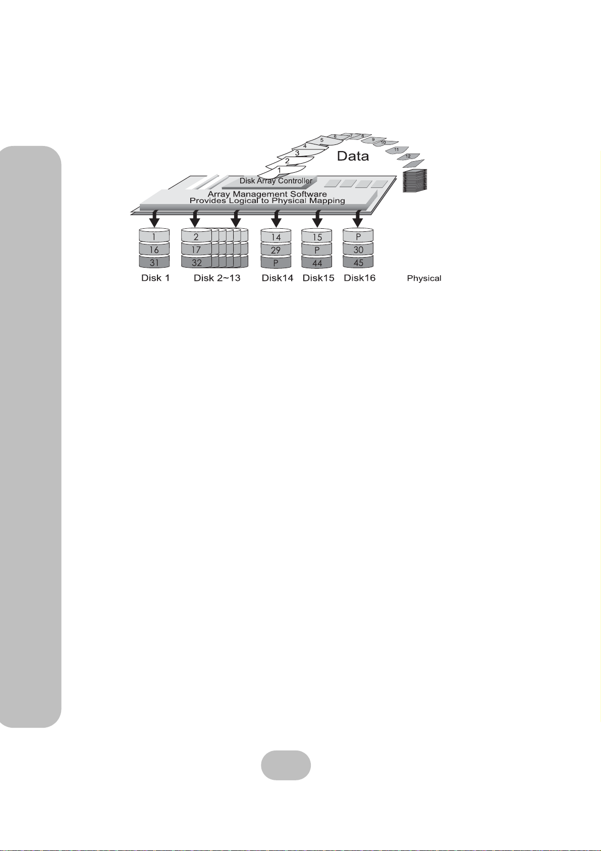
In RAID 5, data is divided into pieces; the parity of these pieces is calculated; and the pieces and
parity are written to separate disks in parallel. The parity is written to a different disk each time.
Parity provides redundant information about the data on other disks. If a single disk fails, then
the data on the other disks is used to regenerate the data on the failed disk. Striping delivers a
high access rate and parity delivers good data availability. The bottleneck caused by the single
parity disk of RAID 3 is not present in RAID 5, since parity is stored on all disks.
RAID 5 consists of two or more disks used for data and one additional disk used for fault tolerence. The total capacity of RAID 5 is the sum of the capacities of each data disk. Add disks
until the desired capacity is reached, then add one more disk for fault tolerance.
RAID 5 is best used with applications whose data has the following characteristics:
• The data is worth protecting, but not as much as RAID 1
• High read data rates
• Small proportion of writes to reads
Hot Spare Disks
A hot spare disk is a standby disk that is not used for data storage unless a RAID member fails. If
a disk failure occurs, the failed RAID member is replaced by the hot spare disk without user
intervention. This improves data availability , since the RAID is able to tolerate more disk failures
with a hot spare disk.
RAID Combinations
RAID levels may be combined in the following hierarchies:
• RAID 0+1 is a RAID 1 consisting of RAID 0 members
• RAID 30 is a RAID 0 consisting of RAID 3 members
• RAID 50 is a RAID 0 consisting of RAID 5 members
6
Page 16
ERQ12-U4R2 & ERQ12-F2R2 Serial ATA Disk Array Systems
Summary of RAID Levels
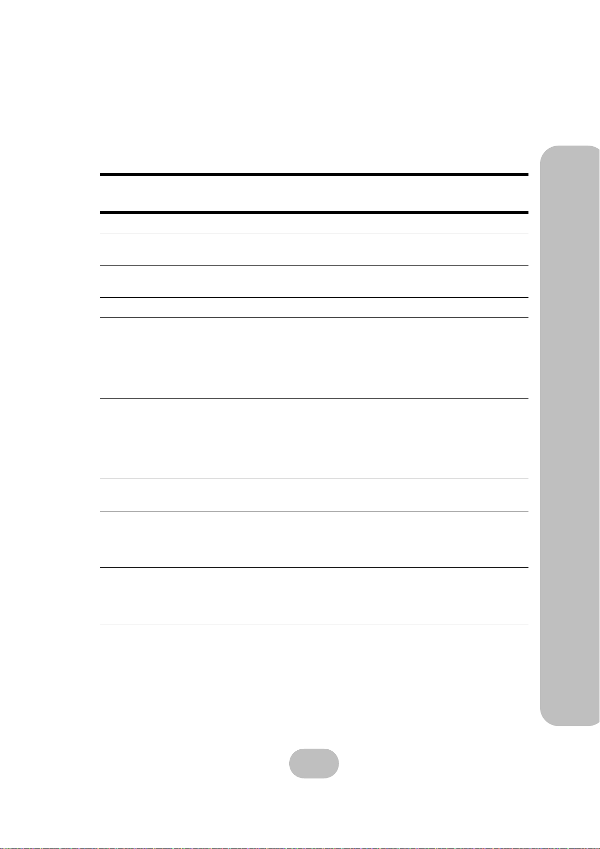
The following table summarizes the performance characteristics of each RAID level. A high
availability or access rate number indicates high availability or quick access rate.
1 Overview – Understanding RAID
Array
Group
NRAID 1 1 100% Sum of all disks in the array
JBOD 1 1 100% Data is distributed by filling each
RAID 0 1 5 100% Data is divided into pieces and
RAID 1 5 2 50% Data is duplicated on both disks.
RAID 3 3 3 Between 67%
RAID 5 3 3.5 Between 67%
Availability
Access
Rate
Capacity
Utilization
for 3 disks to
94% for 16
disks
for 3 disks to
94% for 16
disks
Description
disk in turn.
written to all disks in parallel.
Data is divided into pieces; the
parity of these pieces is calculated; and the pieces are written
to separate disks in parallel with
the writing of the parity to a dedicated disk.
Data is divided into pieces; the
parity of these pieces is calculated; and the pieces and parity
are written to separate disks in
parallel. The parity is written to a
different disk each time.
RAID 0+1 4.5 5 50% RAID 0+1 is a RAID 1 consisting
of RAID 0 members.
RAID 30 4 4 Between 67%
for 6 disks to
88% for 16
disks
RAID 50 4 4.5 Between 67%
for 6 disks to
88% for 16
disks
RAID 30 is a RAID 0 consisting
of RAID 3 members.
RAID 50 is a RAID 0 consisting
of RAID 5 members.
7
Page 17
ERQ12-U4R2 & ERQ12-F2R2 Serial ATA Disk Array Systems
System Requirements
1 Overview – System Requirements
Ensure that the following requirements are met before installing the disk array system.
Operating Environment
• 15 cm (6-inches) of space around the disk array system for proper ventilation
• ambient temperature of 5°C to 40°C (40°F to 104°F)
• ambient non-condensing relative humidity of 10% to 85%
• dust, smoke, and oil free environment
• no large magnetic fields, such as those generated by a high voltage power cables and
motors, etc.
• no direct sunlight
• a flat, stable surface capable of supporting the disk array system
VT100 Terminal Settings
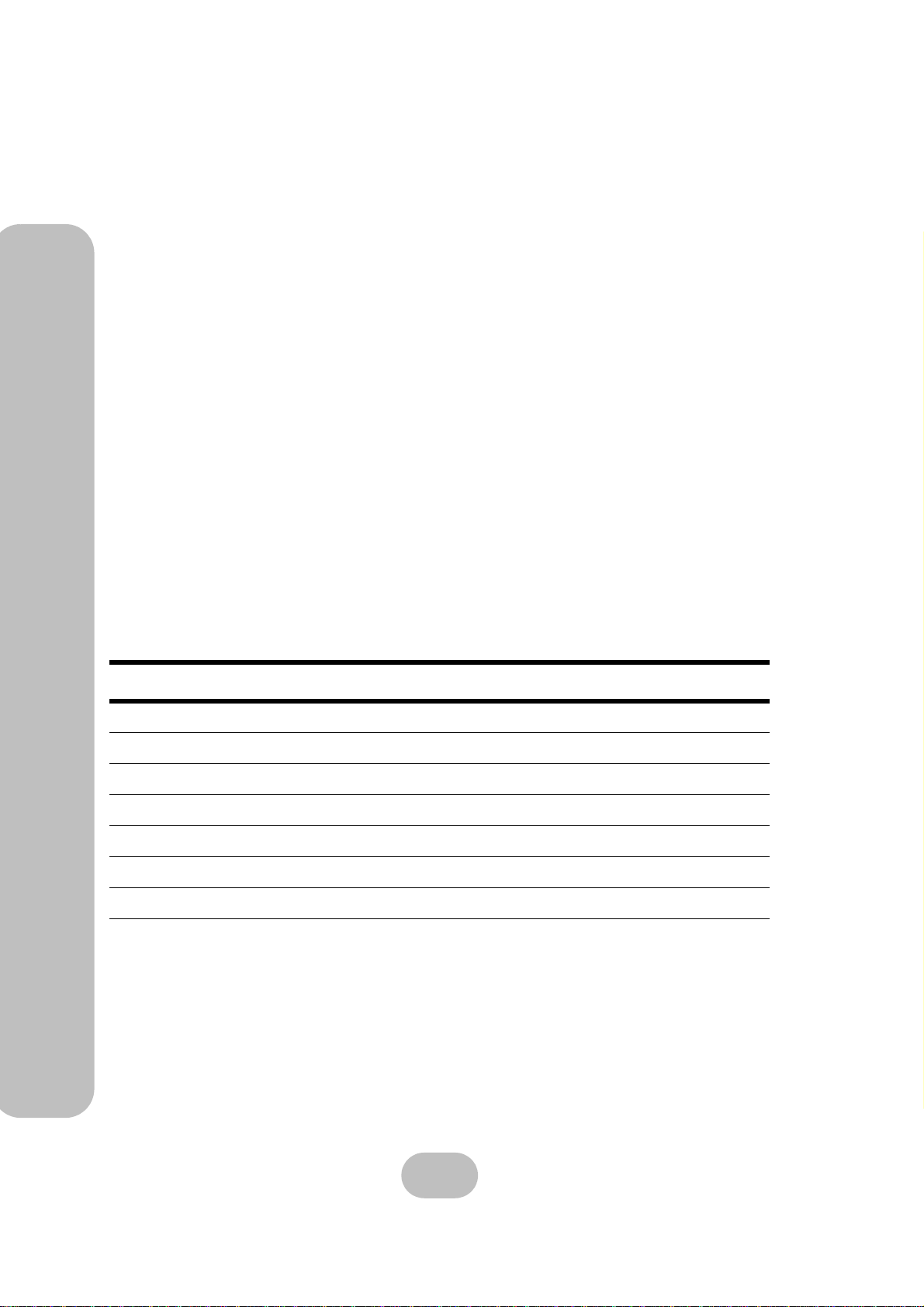
Refer to the following table for a summary of VT100 terminal settings required to communicate
with the disk array system. Refer to your system manual for instructions on setting up the VT100
terminal settings.
Item Required Setting
Connection Serial Port (COM1 or COM2)
Protocol RS232 (Asynchronous)
Cabling Null Modem cable
Baud Rate 115, 200
Data Bits 8
Stop Bit 1
Parity None
8
Page 18
ERQ12-U4R2 & ERQ12-F2R2 Serial ATA Disk Array Systems
Host Interface
The disk array system has either dual SCSI interfaces or dual fibre channel interfaces. Refer to
the following sections to understand host interface system requirements.
Small Computer Systems Interface
The SA-7230 has dual Ultra320 SCSI interfaces that are compatible with previous SCSI standards. Refer to the following table to understand SCSI bus requirements.
Note
Subtract the internal cable length (30 cm) from the maximum SCSI bus
length to calculate the maximum external SCSI cable length.
1 Overview – System Requirements
SCSI
Standard
Ultra320 12 320 15
Ultra160 12 160 15
Ultra2 12 80 15
Ultra Wide 1.5 40 7
Fast Wide 3 20 15
Ultra 1.5 20 7
Maximum
SCSI Bus Length
in Meters
Data Rate
in Megabytes
per Second
Maximum
Number of Devices
Fibre Channel Interface
The SA-7231 has dual 2 Gbit fibre channel interfaces with SFP connectors for linkage to a fibre
channel switch or host computer interface card. With the correct SFP transceiver and optical
cable, the following transmission distances can be achieved.
Component Optical
SFP Transceiver LC Optical
Cable Short Wave Long Wave
Maximum Cable Length 50m 10 Km
Hard Disks
Supply the number of SATA disks needed for your application. Refer to “Understanding RAID”
on page 3 to determine the number of disks needed.
9
Page 19

Page 20
2 Basic Configuration
This chapter describes disk array system connections and disk installation.
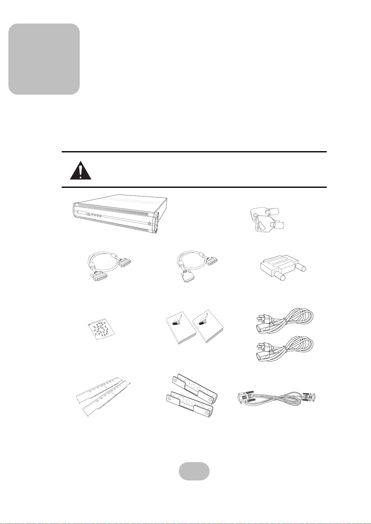
Unpacking
Contact your supplier if any of the following items are missing or damaged.
Caution
The disk array system is heavy. Be careful when lifting and moving it.
Disk Array System
HPD to HPD Ultra320 SCSI
Cable (ERQ12-U4R2 Only)
Screw pack
Rails
HPD to VHDC Ultra320 SCSI
Cable (ERQ12-U4R2 Only)
A
T
A
l
a
i
r
SA-7230
A
T
A
l
a
i
r
e
S
o
t
I
S
C
S
m
e
t
0
s
2
y
3
S
a
y
r
a
t
r
l
r
U
A
k
A
T
is
D
A
l
a
i
r
e
S
o
t
l
&
e
n
n
m
a
Hardware User Manual
e
h
t
s
C
y
SA-7231
e
S
r
y
a
b
r
i
r
F
A
k
s
i
D
SA-7230
e
S
o
t
I
S
C
S
TA
0
2
A
3
l
a
r
ia
t
r
l
e
U
S
Disk Array System
Hardware User Manual
l to
e
n
m
n
e
t
a
&
s
h
y
S
C
y
a
re
r
SA-7231
r
ib
A
F
k
s
i
D
Hardware and software
user Manuals
Rail Extenders
Front Panel Keys
Terminator
(ERQ12-U4R2 Only)
Power Cables
RS-232 Cable
11
Page 21
ERQ12-U4R2 & ERQ12-F2R2 Serial ATA Disk Array Systems
Components
2 Basic Configuration – Components
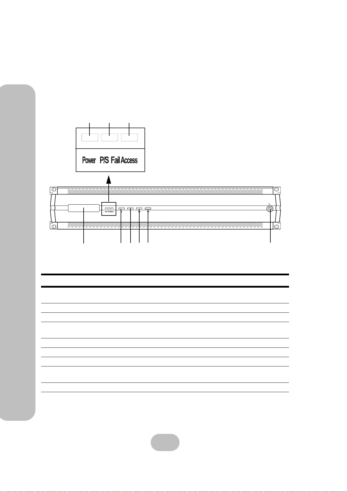
Closed Front Panel
34
1
No. Name Description
1 LCD panel
2 Power-on indicator Indicates the disk array system power is on.
3 Power supply fail indicator Indicates a failed power supply.
4 Host computer access indicator
5 Up function button Moves up in the LCD menus.
6 Down function button Moves down in the LCD menus.
7 Enter function button Selects a menu item or confirms a choice or entry.
8 Escape function button
9 Front panel door lock Secures the front panel door.
56
728
9
Displays warning, operating, and configuration
information.
Indicates data transfer between the disk array system and the host computer.
Returns to the previous LCD menu without making
changes.
12
Page 22
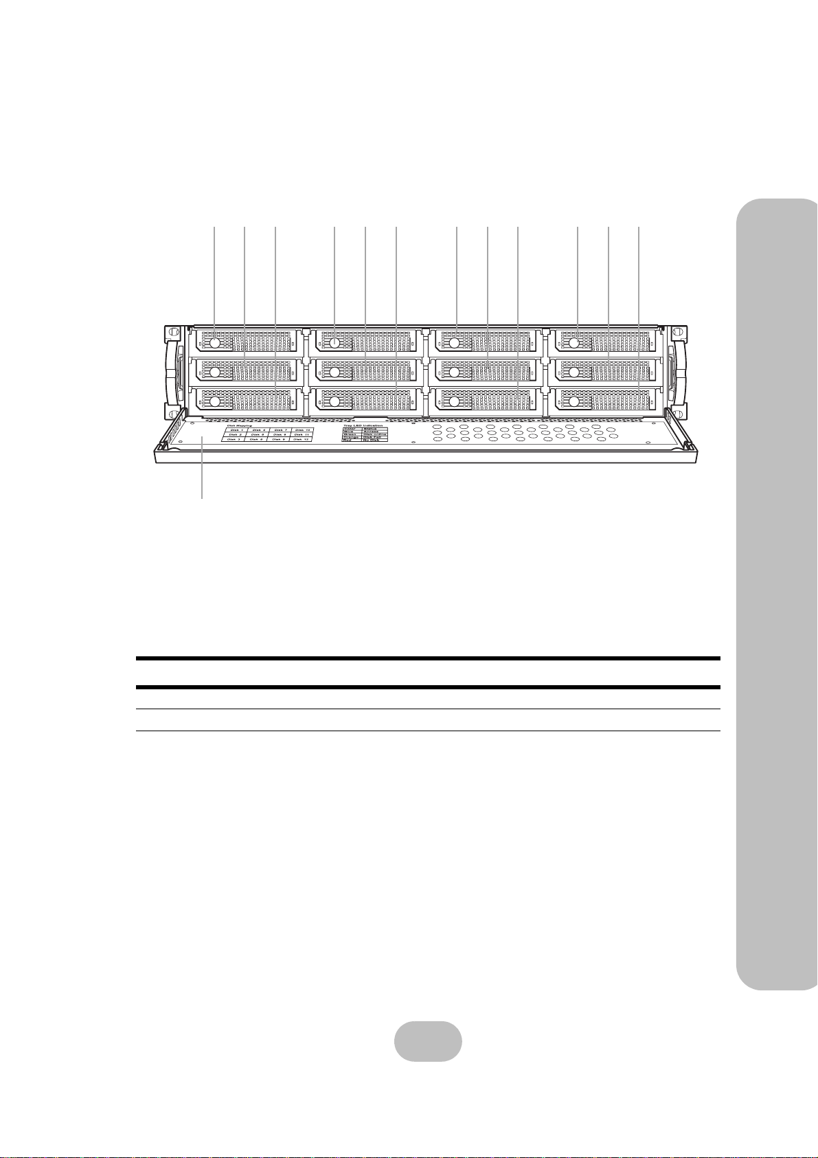
Open Front Panel
ERQ12-U4R2 & ERQ12-F2R2 Serial ATA Disk Array Systems
123 456 789 101112
13
2 Basic Configuration – Components
No. Name Description
1-12 Disk trays 1 to 12 Removable hot swap disk trays.
13 Front panel door Protects the disks and houses the LCD Panel.
13
Page 23
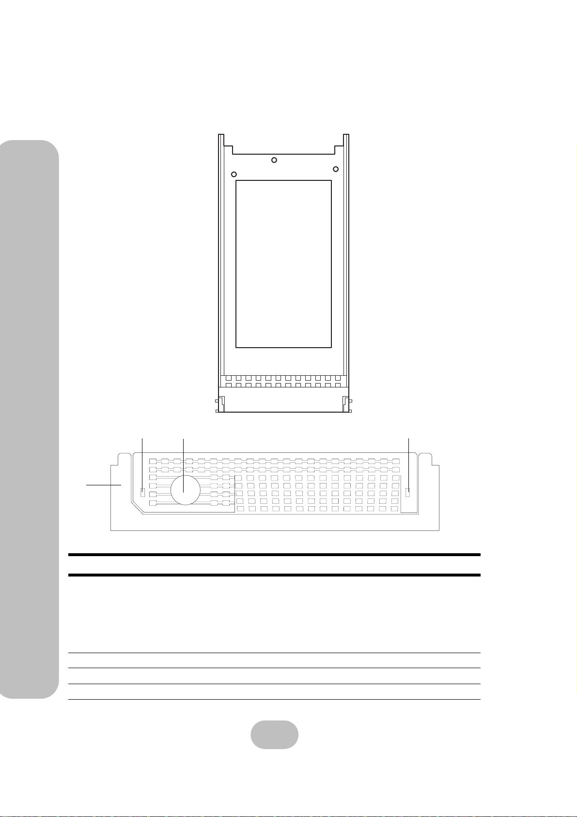
ERQ12-U4R2 & ERQ12-F2R2 Serial ATA Disk Array Systems
Disk Tray
2 Basic Configuration – Components
Front
2
3
No. Name Description
Power/Error indicator LED Different colors indicate different disk states:
1
2 Access indicator LED Indicates that the disk is being accessed.
3 Tray handle Releases the disk tray.
4 Push Button Push the button to release the Disk tray handle.
4
• Blue – Disk access
• Green – Disk online
• Orange – Disk full
• Red – No disk
1
14
Page 24
ERQ12-U4R2 & ERQ12-F2R2 Serial ATA Disk Array Systems
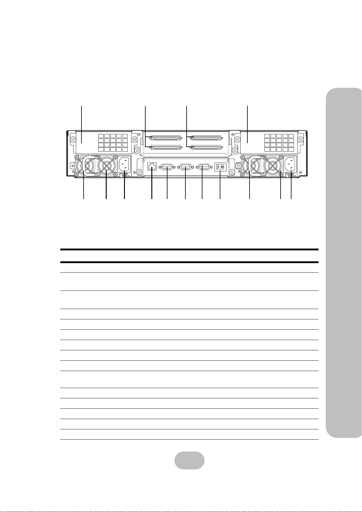
ERQ12-U4R2 Rear View
1
2
Host Port 2
Term MODEM UPS
3
Host Port 1
4
91011121314
No. Name Description
1
Cooling fan 1
2
Host Port 2
System cooling fan
Connects to the host server.
(Primary SCSI channel)
3
Host Port 1
Connects to the host server.
(Secondary SCSI channel)
4
Cooling fan 2
5
Power Supply AC In
6
Power Supply 2
7
Power Supply Handle
8
Power Supply Switch
9
UPS port
10
Modem Port
11
RS-232 Port
12
Ethernet Port
13
Power Supply AC In
14
Power Supply 1
15
Power Supply Handle
System cooling fan
Connects to a 100-240 VAC power source.
Removable redundant power supply 2.
For power supply removal
Switches the power on or off.
Data port for uninterruptable power supply
Connects to a modem for sending remote
alerts.
Connects to a VT100 terminal or equivalent.
Used for browser-based configuration.
Connects to a 100-240 VAC power source.
Removable redundant power supply 1.
For power supply removal
2 Basic Configuration – Components
678
515
15
Page 25
ERQ12-U4R2 & ERQ12-F2R2 Serial ATA Disk Array Systems
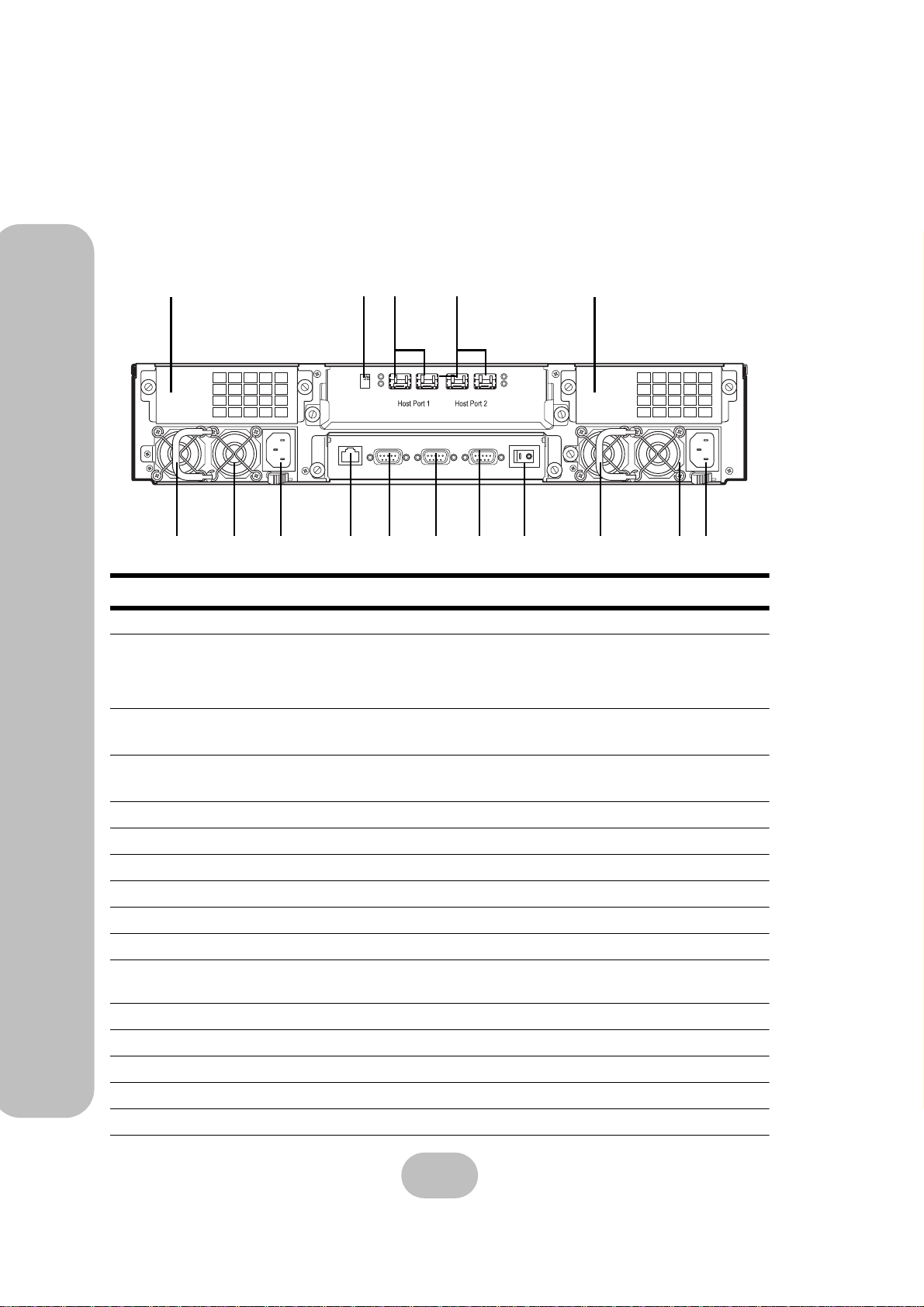
ERQ12-F2R2 Rear View
2 Basic Configuration – Components
3
1
2
Term MODEM UPS
4
5
16
15
91011121314
No. Name Description
1
Cooling fan 1
2
Port select switch
System cooling fan
Selects speed for host ports 1 and 2:
• Up – 1 Gbps
• Down – 2 Gbps
3
Host Port 1
Connects to the host server.
(Primary fibre channel)
4
Host Port 2
Connects to the host server.
(Secondary fibre channel)
5
Cooling fan 2
6
Power Supply AC In
7
Power Supply 2
8
Power Supply Handle
9
Power Supply Switch
10
UPS port
11
Modem Port
12
RS-232 Port
13
Ethernet Port
14
Power Supply AC In
15
Power Supply 1
16
Power Supply Handle
System cooling fan
Connects to a 100-240 VAC power source.
Removable redundant power supply 2.
For power supply removal
Switches the power on or off.
Data port for uninterruptable power supply
Connects to a modem for sending remote
alerts.
Connects to a VT100 terminal or equivalent.
Used for browser-based configuration.
Connects to a 100-240 VAC power source.
Removable redundant power supply 1.
For power supply removal
678
16
Page 26
ERQ12-U4R2 & ERQ12-F2R2 Serial ATA Disk Array Systems
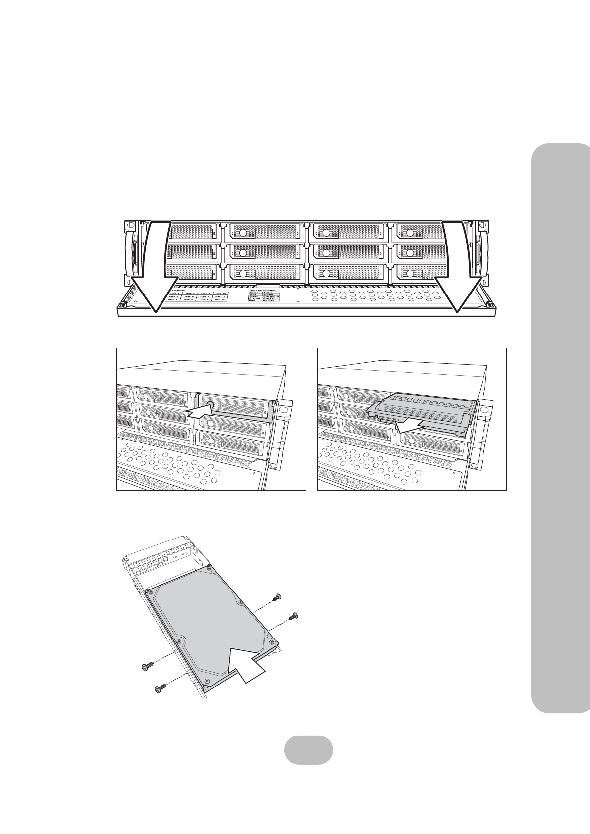
Installing Disks
This section describes how to install disks in the disk array system. Read “Understanding RAID”
on page 3 to decide how many disks are required.
1 Unlock the front panel door, then pull it open.
2 Push the button (A) to release the disk tray handle. Pull the handle (B) to release the tray.
A
B
2 Basic Configuration – Installing Disks
3 Align the rear of the disk with the rear of the disk tray.
4 Insert the disk into the disk tray and fix into place with screws supplied with the disk.
17
Page 27
2 Basic Configuration – Installing Disks
ERQ12-U4R2 & ERQ12-F2R2 Serial ATA Disk Array Systems
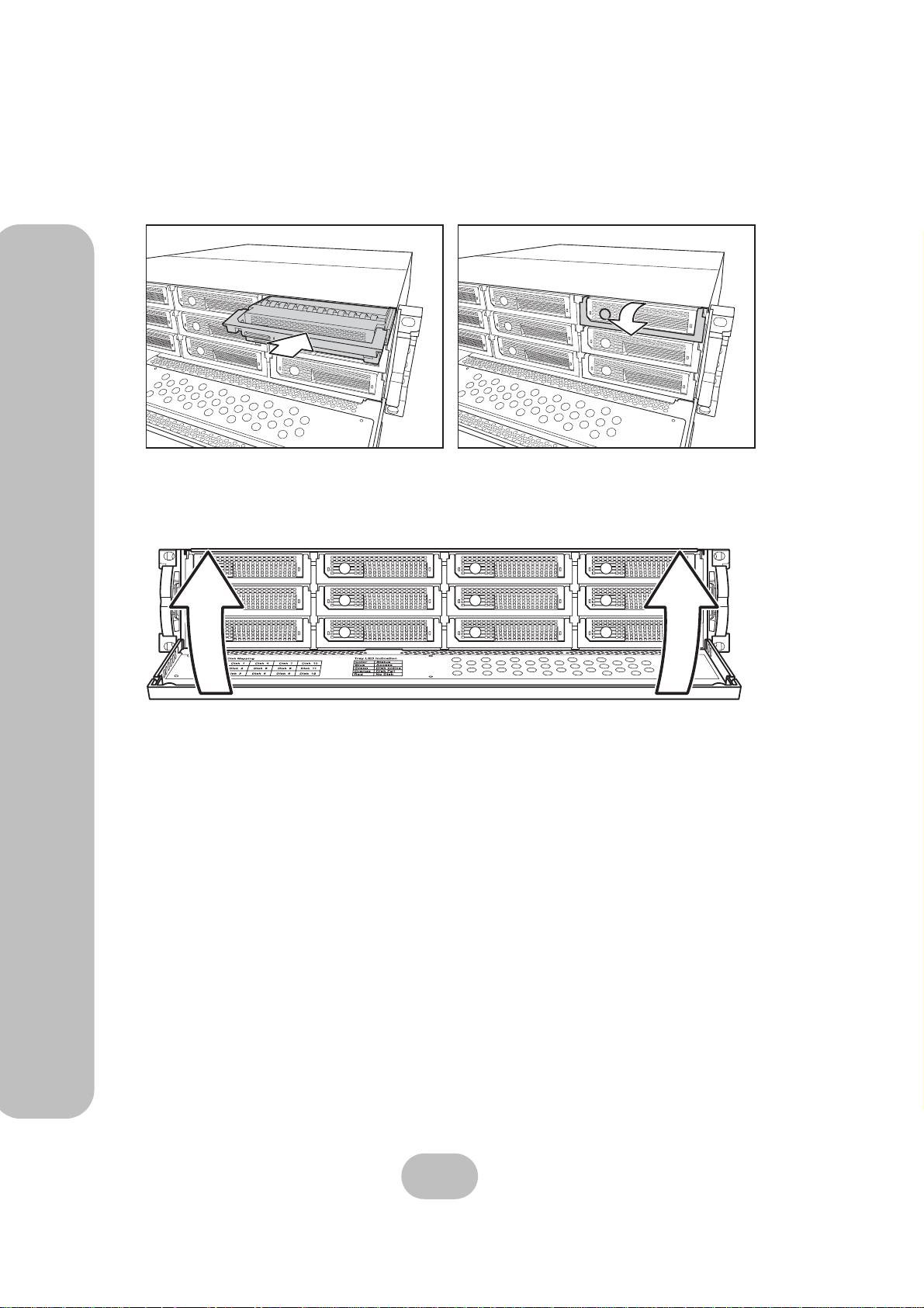
5 Slide the disk tray back into the empty slot (A), then slowly close the disk tray handle
(B).
A
6 Repeat steps 2 to 5 until all of the required disks have been installed.
7 Push the front panel door closed, and lock it.
B
18
Page 28
ERQ12-U4R2 & ERQ12-F2R2 Serial ATA Disk Array Systems
Making Connections
After the required number of disks have been installed, external connections to the disk array
system must be made. This section describes how to make all of the necessary connections.
Connecting the Host Interface
The disk array system has either dual SCSI interfaces or dual fibre channel interfaces. Refer to
the following sections to make host interface connections.
Small Computer Systems Interface
The ERQ12-U4R2 has dual Ultra320 SCSI interfaces. Follow these instructions to make connections.
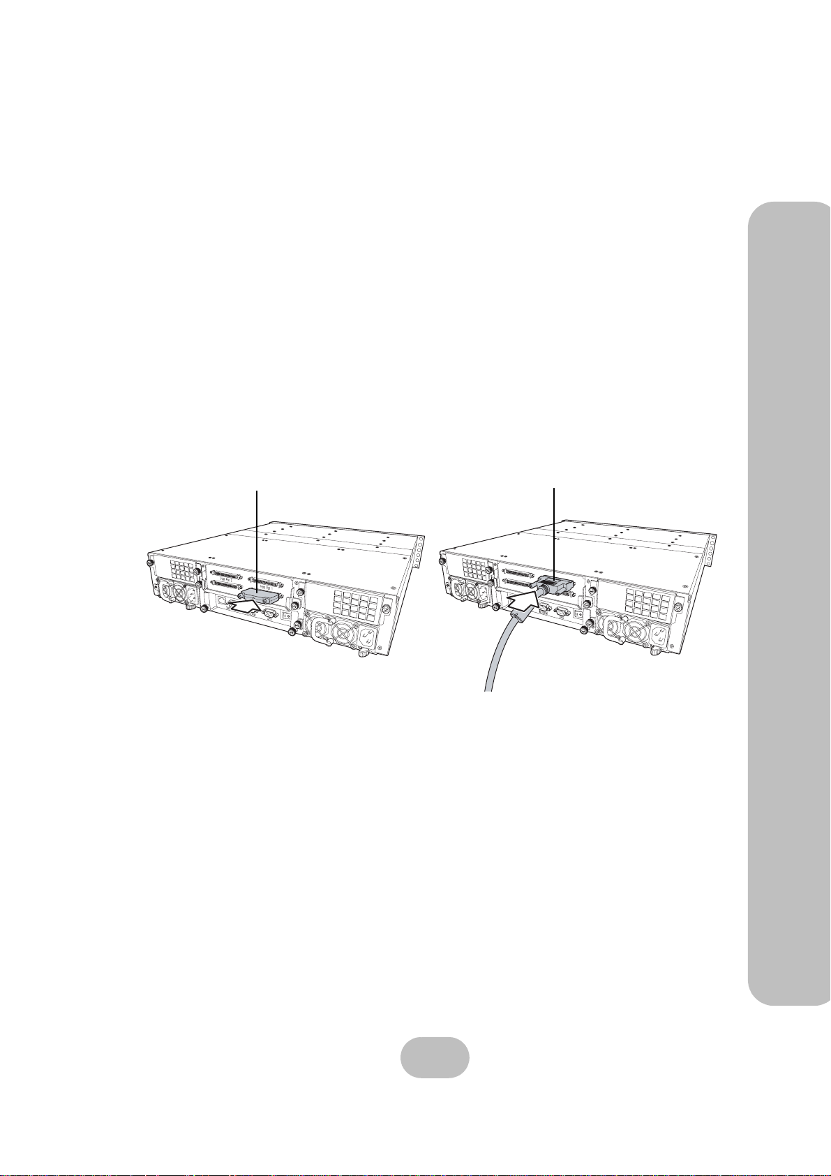
1 Connect the SCSI terminator (A) to the bottom connector of the ERQ12-U4R2 host port
1 (primary SCSI channel) at the rear of the disk array system.
A
B
oGGwGGY
2 Basic Configuration – Making Connections
F
a
n
F
Power 1
an
1
Power 1
1
2 Connect the Ultra320 SCSI cable (B) to the top connector of the ERQ12-U4R2 host port
1 (primary SCSI channel) at the rear of the disk array system.
19
Page 29
ERQ12-U4R2 & ERQ12-F2R2 Serial ATA Disk Array Systems
Fibre Channel Interface
The ERQ12-F2R2 has dual 2 Gbit fibre channel interfaces. Each interface can be used with optical
or copper transceivers and cables. Follow these instructions to make optical connections.
2 Basic Configuration – Making Connections
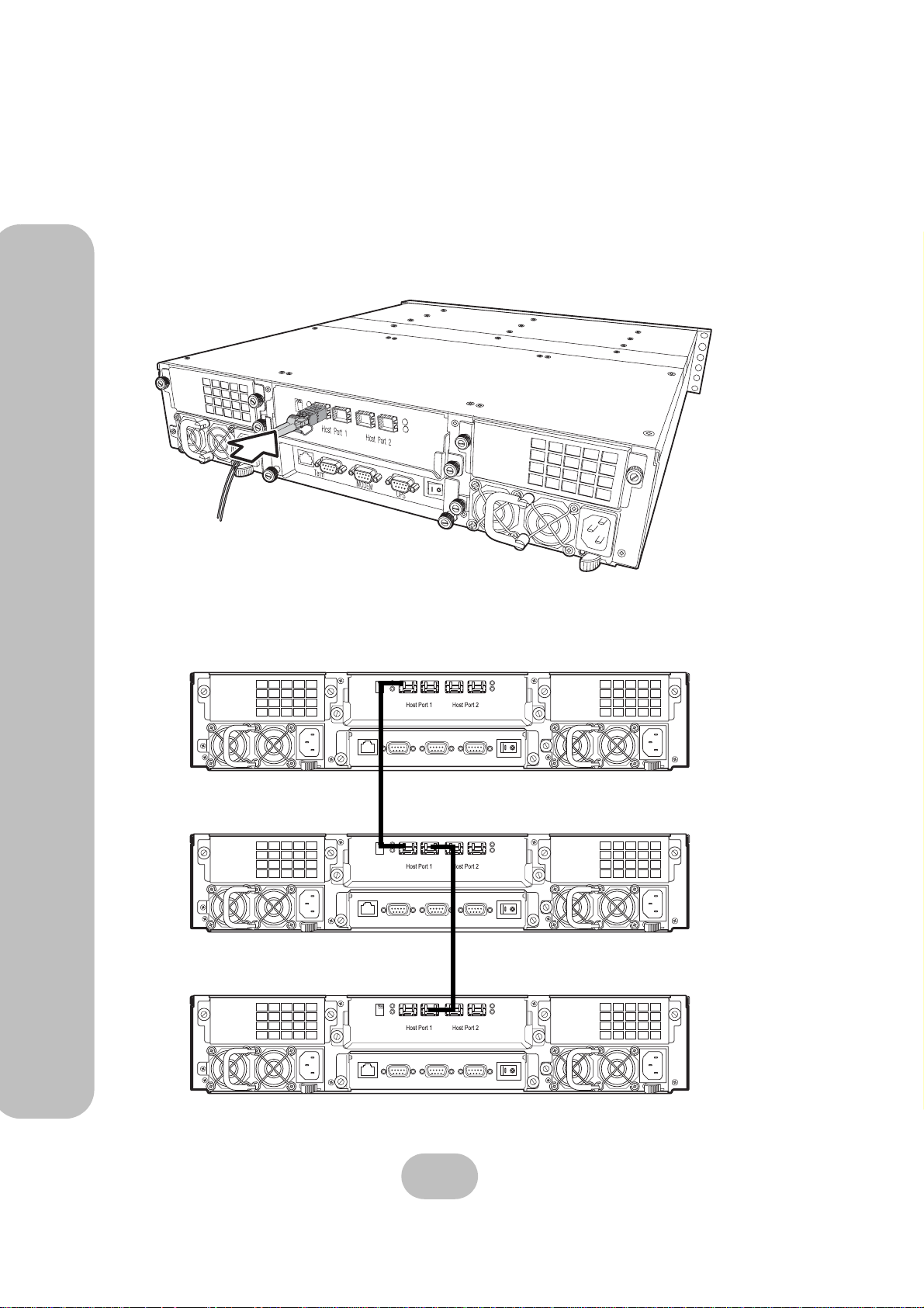
1 Insert fibre cable into the ERQ12-F2R2 host port 1 (primary fibre channel) at the rear of
the disk array system.
Fan 1
Power 1
Fibre Channel Daisy Chaining
Four-port models can be daisy chained as shown in the following diagram.
Term MODEM UPS
Term MODEM UPS
Term MODEM UPS
20
Page 30
ERQ12-U4R2 & ERQ12-F2R2 Serial ATA Disk Array Systems
Connecting a network
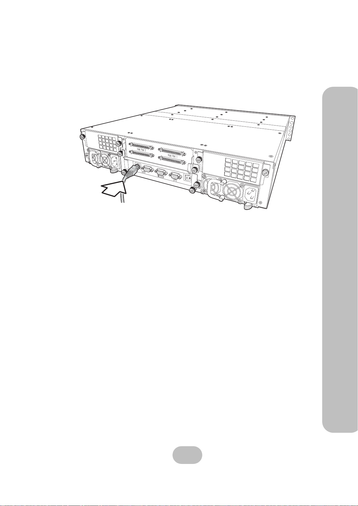
Connect the network cable to the RJ-45 port at the rear of the unit.
2 Basic Configuration – Making Connections
Fan 1
Power 1
21
Page 31
ERQ12-U4R2 & ERQ12-F2R2 Serial ATA Disk Array Systems
Connecting and Turning on the Power
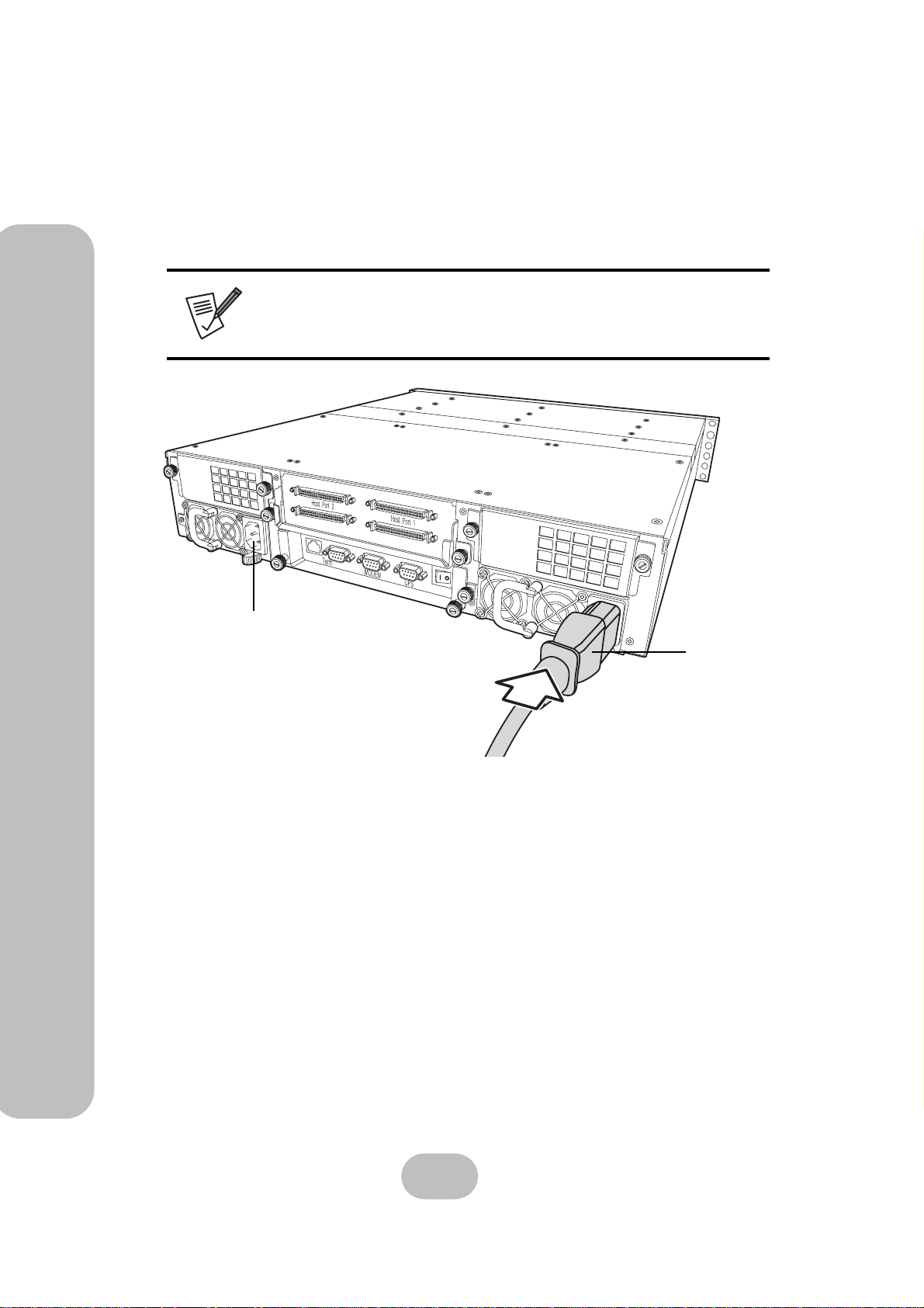
1 Plug a power cable (A) to a power connector at the rear of the unit, then plug the second
2 Basic Configuration – Making Connections
power supply cable into the second power connector (B).
Note
The system is equipped with auto switching power supplies that
can run on 100 to 240 VAC.
B
2 Switch on both power supplies.
Fan 1
Power 1
A
22
Page 32
ERQ12-U4R2 & ERQ12-F2R2 Serial ATA Disk Array Systems
Mounting in a Rack
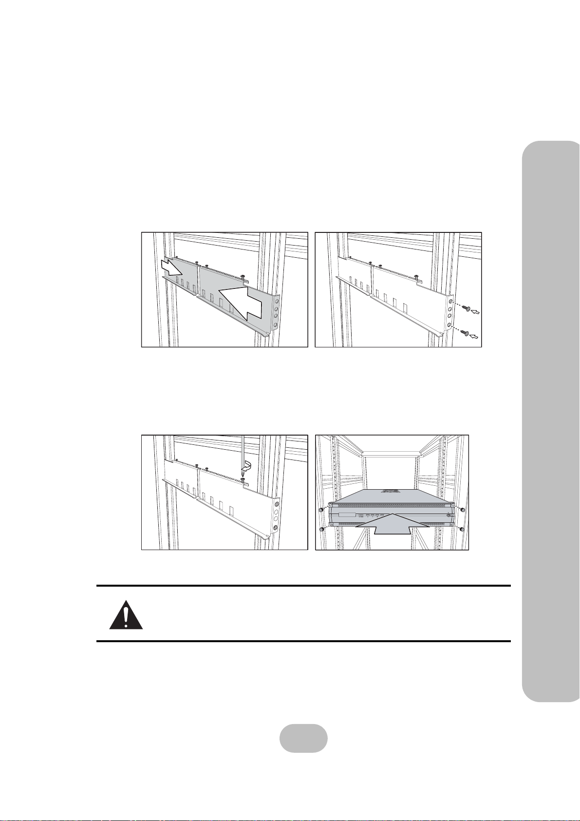
When the disk array system is completely set up, it can be installed in a standard 19-inch rack.
Follow the instructions in this section to install the disk array system in a rack.
1 Clip eight rack nuts supplied with your rack, into the rack, taking care that they corre-
spond with the mounting points on the rails.
2 Extend both of the rails so that they are the right length to fit in your rack.
3 Bolt the rails into the rack using the rack bolts supplied with your rack.
You will need four nuts and bolts (not included) for each rail; two at the front and two
at the back.
4 Tighten the locking screws when they are the correct length.
5 Slide the disk array system into the rack and bolt it into place with the supplied fixing
screws.
2 Basic Configuration – Mounting in a Rack
Caution
This product is heavy . Attempting to install the disk array system in a rack
by yourself could result in injury or damage to the product.
23
Page 33
ERQ12-U4R2 & ERQ12-F2R2 Serial ATA Disk Array Systems
Installing the Rail Extenders
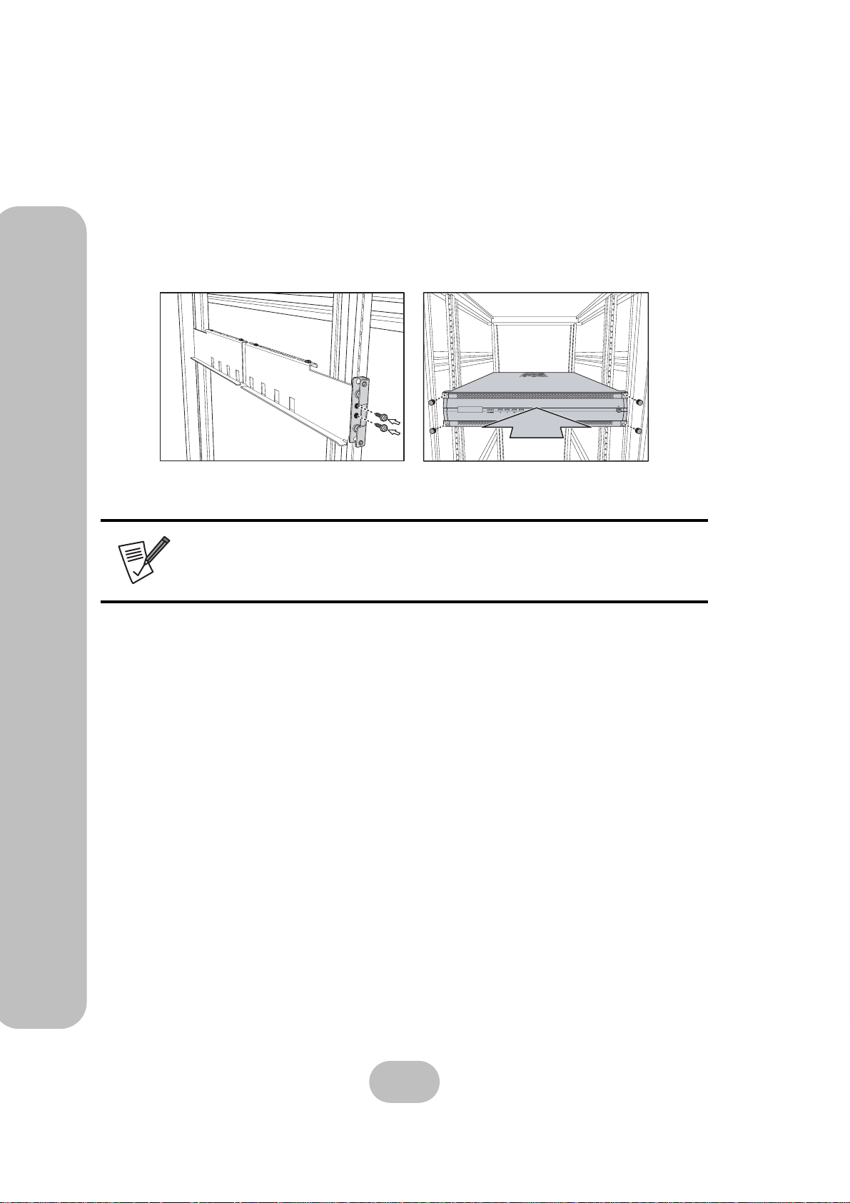
Follow these instructions to fit the rail extenders if required.
2 Basic Configuration – Mounting in a Rack
1 If required, bolt the rail extenders into place as shown using the small bolts provided.
2 Slide the disk array system into the rack and bolt it into place with the supplied fixing
screws.
Note
The rail extenders may be required to allow the disk array system room
for the front door to open correctly.
24
Page 34
3Maintenance
Replacing a Disk
A disk failure is indicated when the Power/Error LED at the front of the drive tray turns red and
the audible alert sounds.
Note
Turn off the audible alert by pressing the Up and Down function buttons on the front panel twice simultaneously.
The LCD panel displays the failure with the symbol “R” or “W”. “R” indicates a disk failure or
error, and “W” indicates that there are too many bad sectors on the disk.
Example:
• Disks 1 to 5 are members of array group 1.
1111122222WR
• Disks 6 to 10 are members of array group 2.
• Disk 11 has too many bad sectors.
• Disk 12 has an error or a fault.
Disks are hot swappable, which means that they can be inserted and removed while the disk array
system is powered on and operating. Follow these instructions to replace a failed disk.
1 Unlock the front panel door, then pull it open.
2 Pull the tray handle away from the disk tray to release it; and pull the disk tray out.
3 Remove the screws from the failed disk, then remove the disk from the disk tray.
4 Align the rear of the new disk with the rear of the disk tray.
5 Insert the new disk into the disk tray.
Note
The new disk must have the same or a greater capacity than the
faulty disk that was removed. If the disk capacity is smaller, the
audible alert sounds and the auto-rebuild operation doesn’t start.
For best performance, it is recommended that the new disk be
identical to the failed disk.
6 Attach the disk to the disk tray with the screws that came with the disk.
7 Slide the disk tray back into the empty slot, then close the disk tray handle.
8 Push the front panel door closed, and lock it.
25
Page 35
ERQ12-U4R2 & ERQ12-F2R2 Serial ATA Disk Array Systems
Replacing a Power Supply
3 Maintenance – Replacing a Power Supply
The disk array system is equipped with a Power Supply Fail Indicator LED at the front of the unit
that turns red when one of the power supplies fails. The message “Power x failure” also appears
on the LCD panel, where x refers to power supply 1, or 2, and an audible alert sounds.
Note
Turn off the audible alert by pressing the Up and Down function buttons on the front panel twice simultaneously.
Power supplies are hot swappable, which means that they can be inserted and removed while the
disk array is powered on and operating. Follow these instructions to replace a failed power supply.
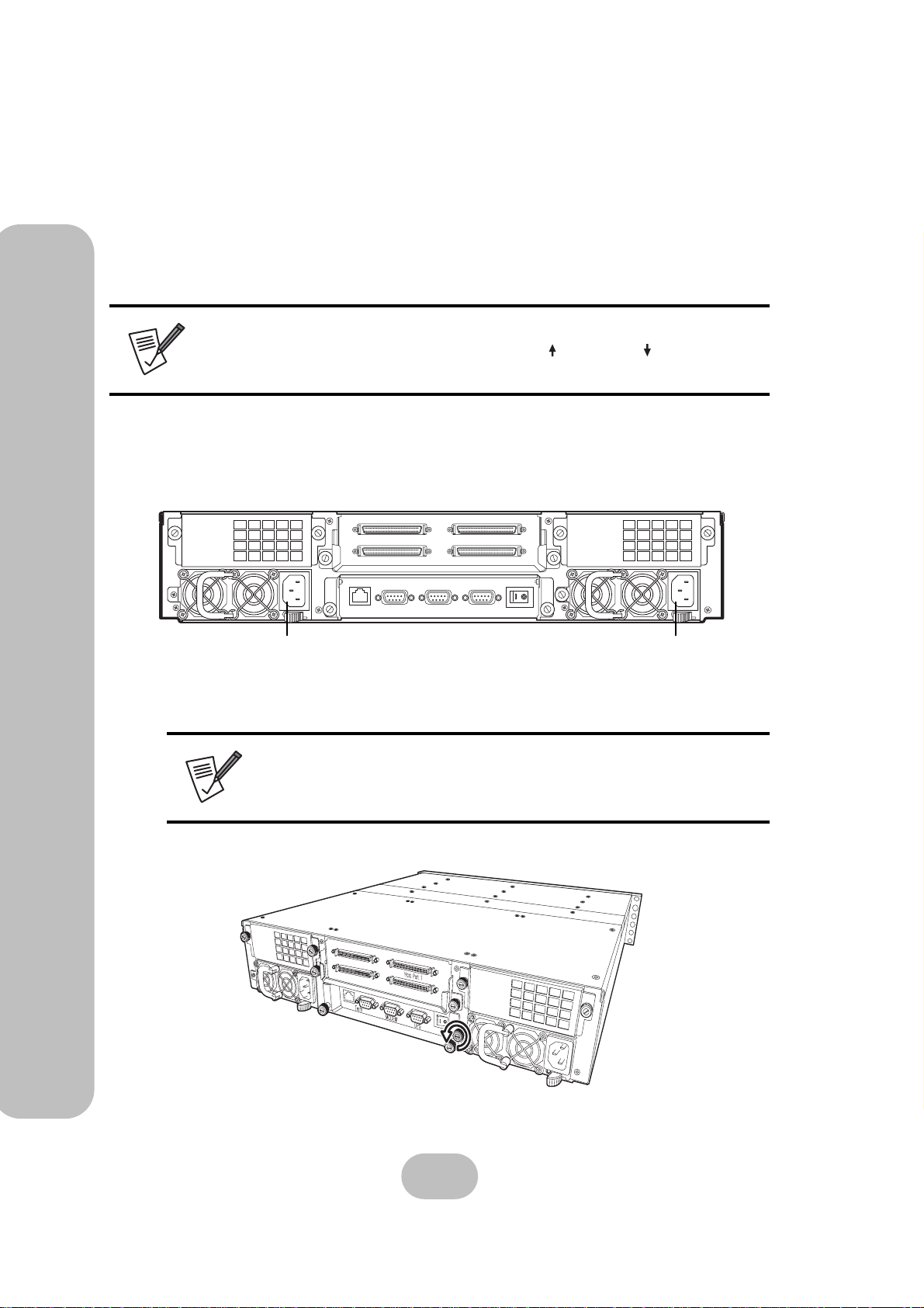
1 Identify the power supply that has failed.
Host Port 2
Term MODEM UPS
Host Port 1
Power Supply 1 Power Supply 2
2 Remove the power cable from the power supply connector at the rear of the unit.
Note
The system is equipped with auto switching power supplies that
can run on 100 to 240 VAC.
3 Loosen the power supply retaining screw.
oGGwGGY
Fan 1
Power 1
26
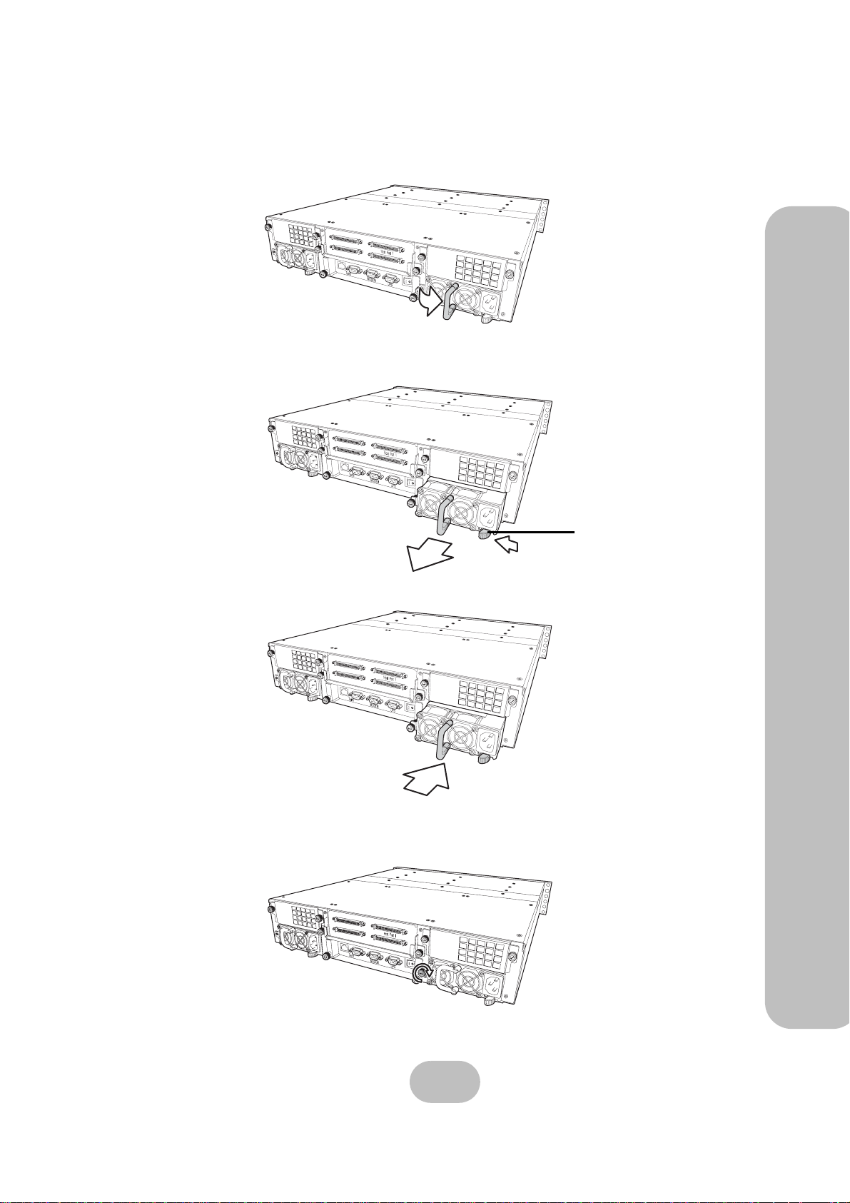
Page 36
ERQ12-U4R2 & ERQ12-F2R2 Serial ATA Disk Array Systems
4 Pull the power supply handle out.
oGGwGGY
Fan
1
Power 1
5 Remove the faulty power supply by pulling the power supply handle and pressing the
release catch.
oGGwGGY
F
a
n 1
Power 1
Release
catch
3 Maintenance – Replacing a Power Supply
6 Insert a new power supply.
oGGwGGY
7 Push the power supp ly handle into place.
8 Tighten the power supply thumbscrew.
oGGwGGY
F
Power 1
F
Power 1
an
1
an
1
9 Reconnect the power cable.
27
Page 37
ERQ12-U4R2 & ERQ12-F2R2 Serial ATA Disk Array Systems
Upgrading Memory
3 Maintenance – Upgrading Memory
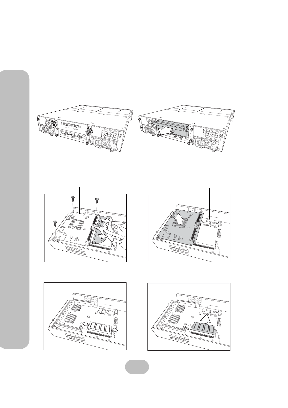
The disk array system takes a single 200 pin PC200 DDR SDRAM SO-DIMM with a maximum
capacity of 1 GB. Follow these instructions to upgrade the memory.
1 Loosen the screws holding the controller cage in place.
2 Lift the handle and slide the controller-cage out of the chassis.
oGGwGGY
F
Power 1
a
n 1
Fan 1
Power 1
3 Carefully remove the cables from the daughter board, remove the three screws, and lift it
away from the array group controller.
Daughterboard
Array group controller
4 Pull the DIMM retaining clips away from the DIMM; the DIMM springs out of the
socket. Remove the DIMM.
28
Page 38
ERQ12-U4R2 & ERQ12-F2R2 Serial ATA Disk Array Systems
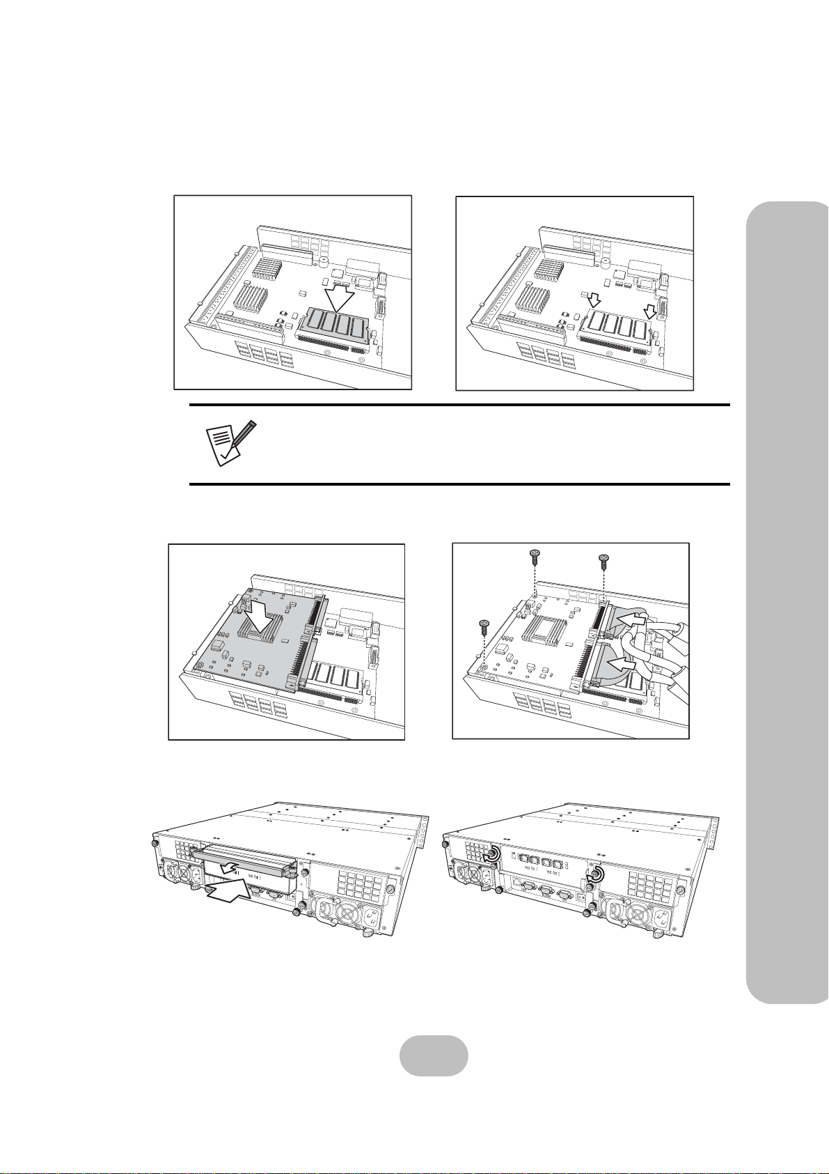
5 Gently push the new DIMM into the socket at 45 degrees, then push the corners of the
DIMM down. The DIMM is secured by the DIMM retaining clips.
Note
The DIMM module will fit in only one direction. Do not force the
DIMM into place.
6 Replace the daughter board on the array group controller, taking care to align the con-
nectors.
3 Maintenance – Upgrading Memory
7 Push the disk controller back in, lower the handle, and tighten the retaining screws.
oGGwGGY
F
a
Power 1
n 1
F
Power 1
a
n 1
29
Page 39

Page 40
Appendix
Hardware Specifications
Item Specification
Host Interface SCSI Ultra320 (ERQ12-U4R2) or Fibre Channel (ERQ12-F2R2)
Disk Interface 12 x SATA, 150 MB/s
Dimensions 88 mm (H) x 446 mm (W) x 498 mm (D)
Weight 25 Kg without disks
RAID Functions • Raid levels: 0, 1, 0+1, 3, 5, 30, 50, JBOD, or NRAID
• Hot spare support
• Disk hot swapping with automatic online rebuilding
• Multiple RAID (max. 8)
Disk Array Functions
Connectors • 4 x 2-Gbit Fibre ports (2 channels), ERQ12-F2R2 model only
Power Supply • Redundant 1 + 1, 350Watt
Warranty 3 year warranty
Safety UL, CE and FCC Class B
• O/S independent and transparent
• 64 MB ~ 1 GB DDR SDRAM
• LCD panel operation indicator
• Audible alarm/disable alarm
• Optional battery backup for disk array status
• LED indicator on disk failures
• 4 x Ultra320 SCSI ports, ERQ12-U4R2 model only
• 1 x RS-232 Serial port (115200, n, 8, 1)
• 1 x RJ-45 Ethernet port (10/100 Mbps)
• 100 - 240 VAC, 47-63 Hz, 6~3A +/- 10%
• Over voltage, current, power, and short circuit protection
• LED indicates power status
• Operating temperature: 0°C ~ 50°C
• Operating humidity: 20 ~ 90%
• Output: +5V, +3.3V, +12V
31
Page 41
SA-7230 & SA-7231 Serial ATA Disk Array Systems
Item Specification
Appendix – Hardware Specifications
Controller
CPU Intel i80321 64-bit RISC microprocessor
Disk Interface Serial ATA I
Disk Channels 12 channels
Disk Interface Chipset Marvell MV88SX8050
Memory Type PC200 DDR 200-pin SO-DIMM
Memory Sockets 1
Memory Size Up to 1 GB
LCD Interface One LCD panel, 2 lines by 16 characters
Button Interface Up, Down, Enter, and ESC
Battery Backup Interface Yes
Daughter Board Interface PCI-X 64-bit, 66/133MHz
Backplane Interface
(connector)
Compact-PCI
Backplane
Disk Channel Support 12 channels
Disk Number Supported 12 disks
Disk Connector Type Serial ATA 1
Temperature Sensors 4
Power Connector Type 2 x Slot-2
Fan Connector Type 2 x Slot-2
32
 Loading...