

Page 1

Ultra 160 SCSI to IDE
Disk Array System
User’s Guide
VVeerrssiioonn 11..00
FFeebb.. 22000033
easyRAID F8P U3TT
®
Page 2
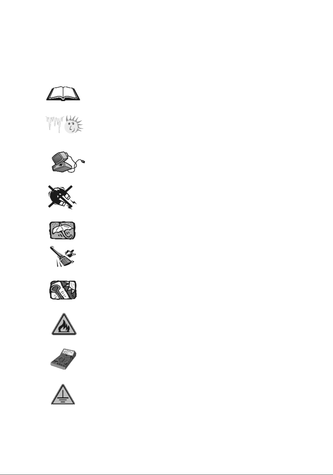
1. Before starting, take a few minutes to
read this manual, read all of these instructions
and save this manual for later reference.
2. Protect the Disk Array from extremely high or low
temperatures. Let the Disk Array warm (or cool ) to
room temperature before using it.
3. Protect the Disk Array from being bumped or
dropped. Do not place this product on an
unstable cart, stand, or table. It may fall, causing
serious damage to the product.
4. Keep the Disk Array away from magnetic forces.
5. Do not use this product near water.
6. Keep the Disk Array away from dust, sand, or dirt.
7. Gaps and openings in the cabinet and the back
are provided for ventilation. To ensure reliable
operation and to protect it from overheating, the
gaps and openings should never be blocked
or covered by placing the product on a bed,
sofa, rug, or other similar surface.
8. Do not place this product near or over a radiator
or heat register.
9. Refer to rating plate for voltage and check the
appliance voltage corresponds to the supply
voltage.
10. The appliance must be grounded. This product is
equipped with a 3wire grounding-type power
cord, this power cord will only fit into a
groundingtype power outlet.
IImmppoorrttaanntt!! SSaaffeettyy IInnssttrruuccttiioonnss,, CCaarree aanndd HHaannddlliinngg
Page 3
11. If an extension cord or a power center is used
with this product, make sure that the total of all
products plug into the wall outlet does not
exceed the ampere rating.
12. Do not place the Disk Array where the cord will
be walked on.
13. Never push any kind of object into this product
through cabinet gaps and openings, they may
touch dangerous voltage points cause a risk of
fire or electric shock.
14. Unplug the power cord from the wall outlet
before cleaning. Keep the Disk Array dry. Do not
use liquid cleaners, aerosol cleaners, or a wet
cloth. Use a damp cloth for cleaning.
15. Except as specifically explained in this User’s
Manual, please do not attempt to service this
product by yourself. Opening or removing the
covers may expose you to dangerous voltages.
16. Unplug this product from the wall outlet and refer
servicing to qualified service personnel under the
following conditions :
If this product has been exposed to water or
any liquid.
If the product has been dropped or the
cabinet damaged.
Page 4
When selecting a suitable working location, please consider :
Ventilation
Temperature
Dust and dirt
Electromagnetic and Radio Frequency Interference.
Security
The selected location should provide at least six inches of open
space around the Disk Array cabinet for proper air flow.
Your Disk Array functions best at normal room temperature. Choose
a location free from extreme heat or cold.
Your Disk Array should be used in a clean environment that is free
from airborne contaminants such as dust, dirt, and smoke. Excessive
moisture or oil particles in the air can also hinder your system’s
performance.
To reduce the possibility of data errors caused by electromagnetic
interference, locate your Disk Array at least five feet away from
electrical appliances and equipment that generates magnetic
fields.
OOppeerraattiinngg EEnnvviirroonnmmeenntt
The Disk Array’s LCD Panel may be damaged by exposure
to intense sunlight. Limit exposure to indirect or subdued
sunlight only.
Warning!!
Page 5
This manual serves as a useful guide you can refer to when you
wish to install and operate your Disk Array. It includes the
following information :
Chapter 1 : “ Introduction “
Introduces you to your new Disk Array’s
features and general RAID concepts.
Chapter 2 : “ Getting Started “
Describes general information about this Disk
Array.
Chapter 3 : “ Configuration “
Provides a Quick and Easy way to setup this
Disk Array.
Chapter 4 : “ Advanced Information “
Describes information in more detail.
Chapter 5 : “ Hot-Swap “
Describes Hot-Swap components.
Appendix A : “ Technical Specification “
AAbboouutt TThhiiss MMaannuuaall
Page 6
CChhaapptteerr 11 :: IInnttrroodduuccttiioonn
Features ..........................................................................1-2
General RAID concepts .....................................................1-4
RAID Level 0 .....................................................1-5
RAID Level 1 .....................................................1-6
RAID Level 3 .....................................................1-7
RAID Level 5 .....................................................1-8
Summary Comparison of RAID Levels ............................... 1-10
Supported RAID Levels .....................................................1-11
Multi-SCSI Format support .....................................................1-12
Contents
CChhaapptteerr 22 :: GGeettttiinngg SSttaarrtteedd
General Overview ............................................................... 2-1
Unpacking & Checklist .................................................... 2-2
Choosing a place for Disk Array .......................................... 2-3
Identifying Parts of Disk Array
Front View .....................................................2-4
Rear View .....................................................2-5
Power Source ................................................................2-6
Installing the Hard Disk Drive .......................................... 2-7
How To Setup Active Terminator .......................................... 2-11
Host Linkage ..........................................................................2-12
Power-On & Self-Test............................................................... 2-13
LED Display & Function Keys
LED Display .......................................... 2-14
Function Keys ..........................................2-15
LCD Status Panel ............................................................... 2-16
Clear Beeper..........................................................................2-17
CChhaapptteerr 33 :: CCoonnffiigguurraattiioonn
General Overview ............................................................... 3-1
Configuration from the front Panel ............................... 3-2
Page 7

Configuration Procedures .......................................... 3-3
Starting the Configuration .......................................... 3-4
Configuration from VT100 Terminal Mode .....................3-7
Configuration Procedures ............................... 3-8
Main Screen .....................................................3-9
Re-config RAID .......................................... 3-10
Set RAID Level ..........................................3-11
Hot Spare Disk .......................................... 3-12
Set SCSI ID# .....................................................3-13
Password .....................................................3-14
Save & Restart .......................................... 3-15
Capacity Expansion..........................................3-16
CChhaapptteerr 44 :: AAddvvaanncceedd IInnffoorrmmaattiioonn
Memory Expansion ............................................................... 4-2
Disk Array Controller Block Diagram........................................ 4-5
Updating Firmware ............................................................... 4-6
Setting Up VT100 Terminal Emulation in Windows 95 .......... 4-7
Start to Update Firmware.................................................... 4-14
Multiple RAID Configuration .......................................... 4-20
Slice and Lun Mapping .....................................................4-29
On-Line Expand for Multiple RAID Groups .....................4-35
CChhaapptteerr 55 :: HHoott SSwwaapp
Removing / Installing Hard Disk Drive ............................... 5-2
Removing / Installing Redundant Power Supply Unit .......... 5-6
Removing / Installing Cooling Fan.......................................... 5-9
AAppppeennddiixx ::
Technical Specifications A-1
Page 8
1-11
Introduction
This chapter will introduce you to your new Disk Array’s features and
provide information on general RAID concept.
Chapter 1: “Introduction”
Page 9
1-22
Introduction
This section provides an overview of the features. For more detailed
information, please refer to the technical specifications appendix
at the end of this manual .
Your Disk Array includes the following features :
EEaassyy OOppeerraattiioonn
As everyone knows, conventional Disk Arrays are designed for
experienced computer specialists. To solve complicated and time
consuming operating procedures, we came up with a revolutionary
idea :
—— IInnnnoovvaattiivvee PPlluugg AAnndd PPllaayy RRAAIIDD ——
As compared to a conventional Disk Array’s long-winded setup
procedures, your Disk Array can be ready to go after using the
simple step by step built-in setup program.
UUllttrraa HHiigghh ppeerrffoorrmmaannccee
Your Disk Array combines an extremely high speed microprocessor
with the latest chip set, IDE hardware technology , perfect firmware
and an artistic design. The result is one of the fastest, most reliable
Disk Array systems on the market.
Supports virtually all popular operating systems, platforms and
network environments because it works independently from the
O.S.
Ultra 160 LVD SCSI channel interface to your Host computer, up
to 160MB data transfer rate provides the processing and access
power for you to handle complex and large files.
Selective SCSI ID 0 ~ 14 , support with active termination.
Tagged-command queuing : allows processing of up to 255
simultaneous data requests.
Selective RAID levels 0, 1, 0+1, 3 or 5 , JBOD.
Build-in 64MB cache memory, expandable up to 512MB.
Serial communication port ( Terminal Port ) permits array
controller operation through a standard VT100 terminal
(or equivalent).
FFeeaattuurreess
Page 10

1-33
Introduction
SSoolliidd rreelliiaabbiilliittyy
Automatic failed disk drive detection.
Auto rebuild : when a replacement disk installed (or by using
hot spare disk ), The system provides automatic data rebuild
without any commands or functions keyed in. ( Transparent to
Host )
EEffffiicciieenntt mmaaiinntteennaannccee
An LCD status panel displays a comprehensive readout of the
operating status, and the HDD LED indicators on each HDD tray
display the individual HDD status.
When disk failure occurs on a member disk of the disk array, the
built-in buzzer sounds simultaneously and LCD status panel also
points out the location of the failed hard disk drive. In the
meantime the LED HDD status indicator will light up “ Red “on
the failed HDD tray , according the LED indicator on the HDD
tray you can perform quick, efficient and correct maintenance.
Hot Swap : allows you to remove and install the “ Hot Swap “
parts without interrupting data access while the system is on.
The “ Hot Swap “ parts include the Hard Disk Drive, Redundant
Power Supply Unit and Cooling Fan.
Page 11
1-44
Introduction
Correct installation of the disk array requires an understanding of
RAID technology and the concepts described in this section.
Definition
RAID is an acronym of Redundant Array of Independent Disks .
A RAID is a Disk Array in which part of the storage capacity is used
to record redundant information about the user data stored on the
remainder of the storage capacity. The redundant information
enables regeneration of user data in the event that one of the
Array’s member Disks or the access path to it fails.
Benefits of RAID
1. Secure Data
RAID is an emerging storage technology with the potential to
revolutionize the data storage technology. A typical RAID unit
contains a set of disk drives, typically two to six, which appear to
the user to be equivalent to a single large capacity disk drive.
The remarkable benefit of disk array is that if any single disk in the
RAID fails, the system and array still continues to function without
loss of data. This is possible because the redundancy data is
stored on separate disk drives and the RAID can
reconstruct the data that was stored on the failed disk drive.
2. Increases system performance
As the effective seek time for finding data on a disk can
potentially be reduced by allowing multiple simultaneous access
of different data on different disks. Utilizing parallel reads and
writes of the data spread across the disks in the array, the data
transfer rate can be increased significantly over that of a single
disk.
3. Easy maintenance
RAID system maintenance is typically simplified because it is
easy to replace individual disks and other components while the
system continues to function. ( Hot swap support )
GGeenneerraall RRAAIIDD CCoonncceeppttss
Page 12
1-55
Introduction
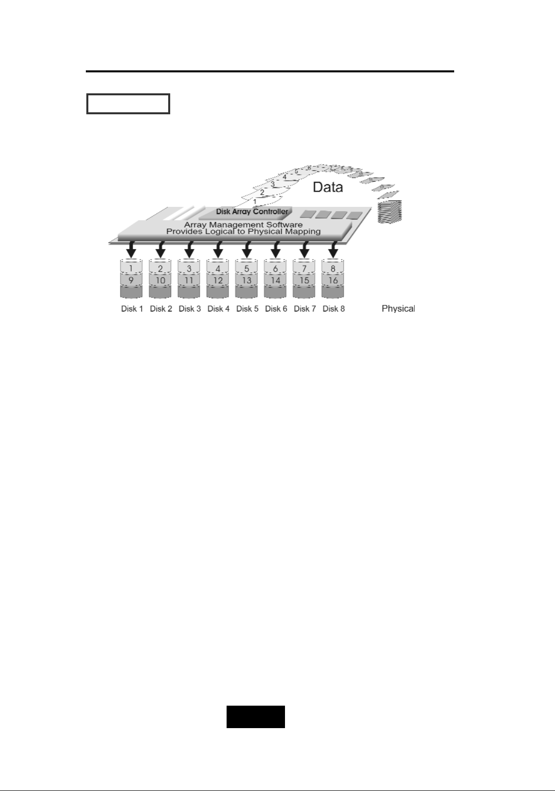
RRAAIIDD LLeevveell 00 :: ““ DDiisskk SSttrriippiinngg ““ HHiigghh II//OO PPeerrffoorrmmaannccee
Improved I/O performance is the major reason of using RAID
level 0.
No protection is provided against data loss due to member
disk failures. A RAID level 0 array by itself is thus an unsuitable
storage medium for data that can not easily be reproduced,
or for data that must be available for critical system operation.
It is more suitable for data that can be reproduced or is
replicated on other media.
A RAID level 0 array can be particularly useful for :
Storing program image libraries or runtime libraries for rapid
loading, these libraries are normally read only.
Storing large tables or other structures of read only data for
rapid application access. Like program images, the data
should be backed up on highly reliable media, from which it
can be recreated in the event of a failure.
Collecting data from external sources at very high data
transfer rates.
RAID level 0 arrays are not particularly suitable for :
Applications which make sequential requests for small
amount of data. These applications will spend most of their
I/O time waiting for disks to spin, whether or not they use
striped arrays as storage media.
Applications which make synchronous random requests for
small amounts of data.
RRAAIIDD LLeevveellss
Page 13
1-66
Introduction
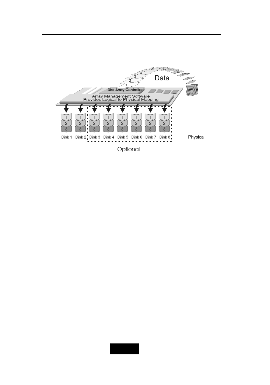
RRAAIIDD LLeevveell 11:: ““DDiisskk MMiirrrroorriinngg”” HHiigghh DDaattaa rreelliiaabbiilliittyy
RAID level 1 provides both very high data reliability and continued
data availability in the event of a failure of an array member. When
a RAID level 1 member disk fails, array management software
simply directs all application requests to the surviving member.
RAID level 1 is suitable for data for which reliability requirements are
extremely high, or for data to which high performance access is
required, and for which the cost of storage is a secondary issue.
Page 14
1-77
Introduction
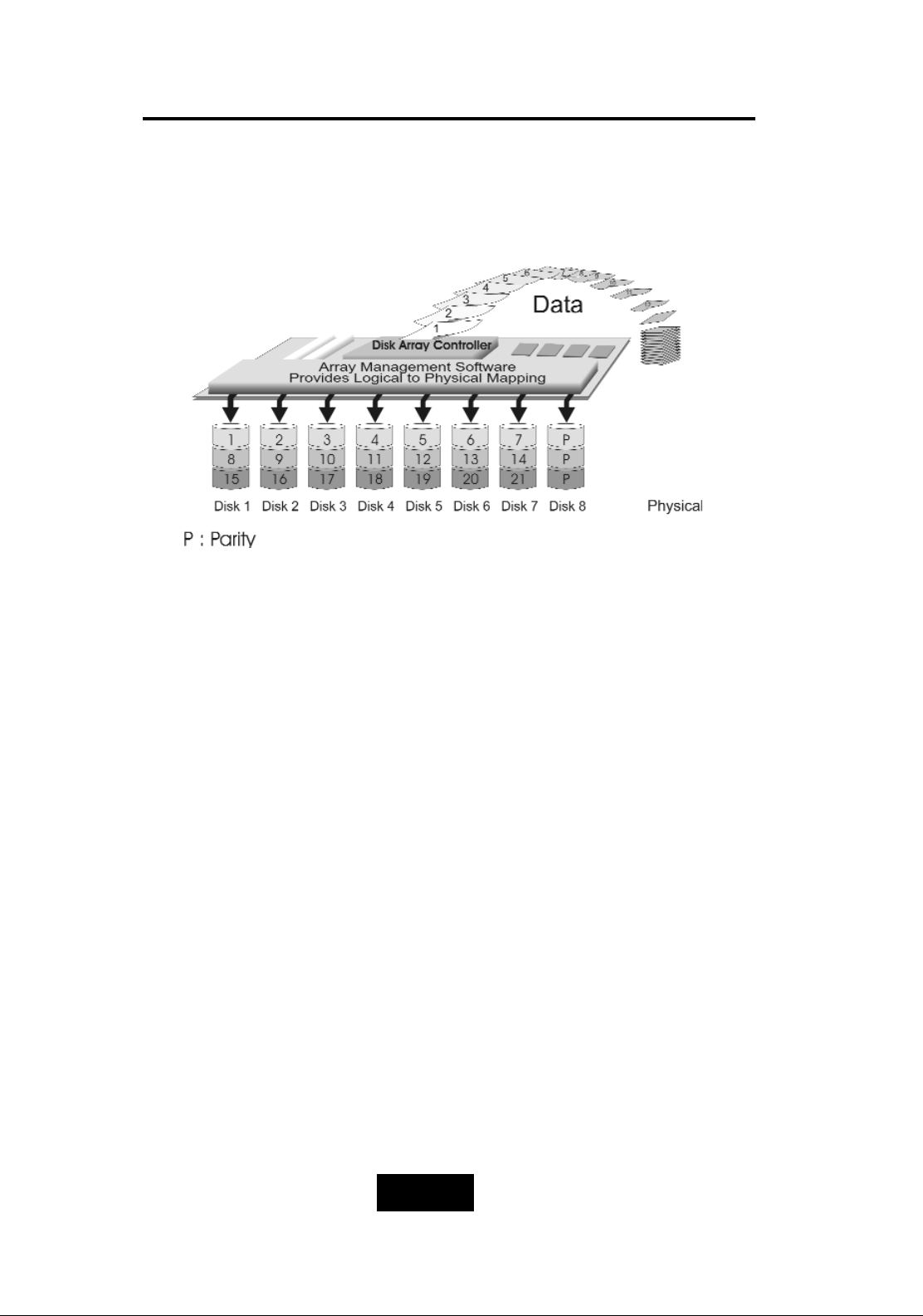
RRAAIIDD LLeevveell 33 ::
““ PPaarraalllleell TTrraannssffeerr DDiisskkss wwiitthh PPaarriittyy ““
HHiigghh DDaattaa RReelliiaabbiilliittyy && HHiigghheesstt TTrraannssffeerr CCaappaacciittyy
RAID Level 3 technology use a dedicated parity disk to store
redundant information about the data on several data disks. RAID
Level 3 is an excellent choice for applications which require single
stream I/O with a high data transfer rate.
RAID Level 3 is optimal for applications in which large block of
sequential data must be transferred quickly, these applications are
usually of one of these types :
They operate on large data objects such as graphical image
processing, CAD/CAM files, and others.
They are non-interactive applications that process large data
sequentially.
They usually request a large amount of data (32KBytes or more)
with each I/O request.
The distinctive performance characteristics of RAID Level 3 :
RAID Level 3 provides excellent performance for data
transfer-intensive applications.
RAID level 3 is not well suited for transaction processing or
other I/O request-intensive applications.
Page 15
1-88
Introduction
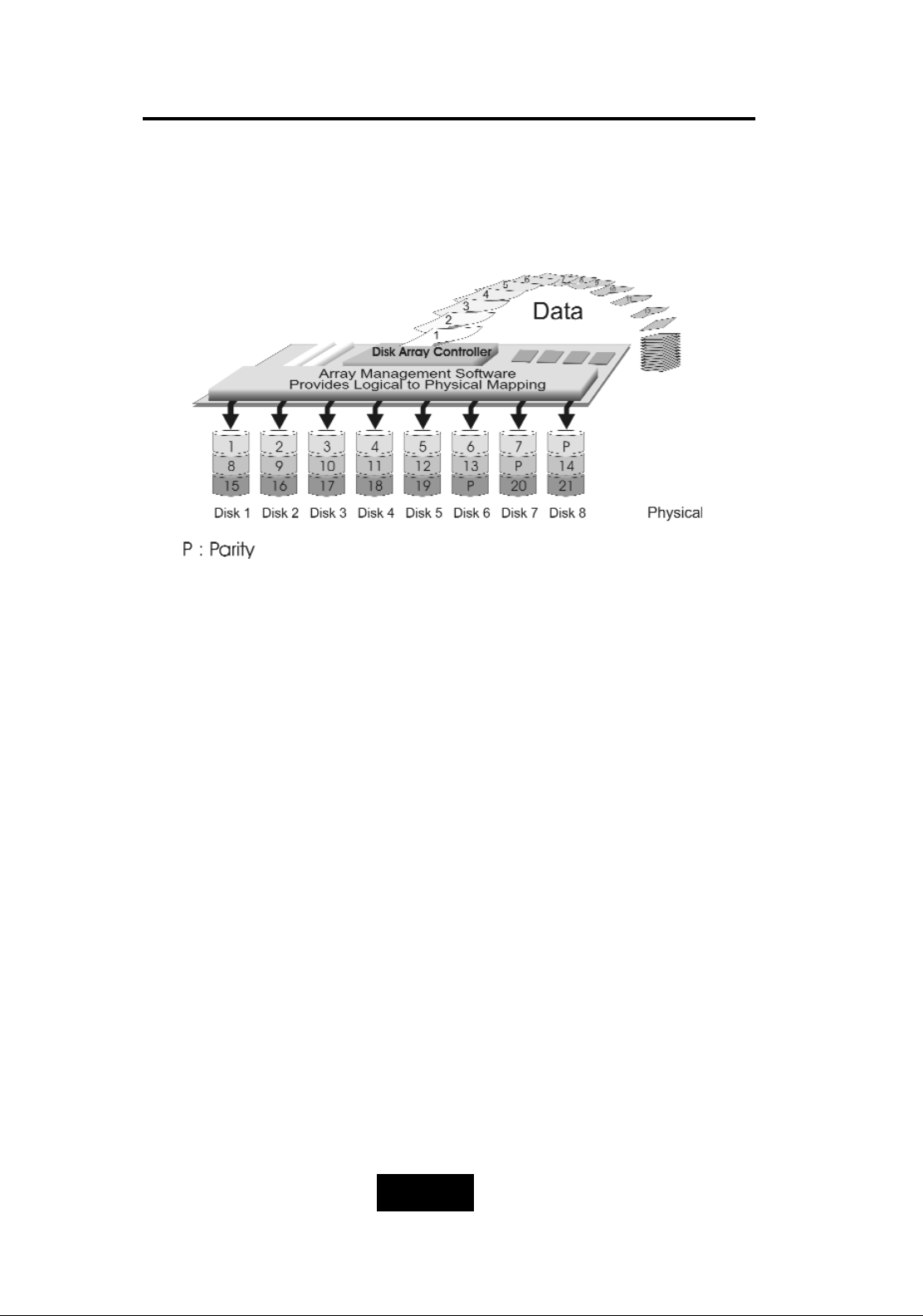
RRAAIIDD LLeevveell 55 ::
““ IInnddeeppeennddeenntt AAcccceessss AArrrraayy wwiitthh RRoottaattiinngg PPaarriittyy ““
HHiigghh DDaattaa RReelliiaabbiilliittyy && TTrraannssffeerr CCaappaacciittyy
When RAID Level 5 technology is combined with cache memory to
improve its write performance, the result can be used in any
applications where general purpose disks would be suitable.
For read only or read mostly application I/O loads, RAID Level 5
performance should approximate that of a RAID Level 0 array. In
fact, for a given user capacity, RAID Level 5 read performance
should normally be slightly better because requests are spread
across one more members than they would be in a RAID Level 0
array of equivalent usable capacity.
A RAID level 5 array performs best in applications where data
and I/O load characteristics match their capabilities :
Data whose enhanced availability is worth protecting, but for
which the value of full disk mirroring is questionable.
High read request rates.
Small percentage of writes in I/O load.
Page 16

1-99
Introduction
RAID level 5 arrays have unique performance characteristics :
The data can be recalculated or regenerated, using parity,
when any drive in the array fails.
When the failed drive is replaced, either automatically if the
subsystem contained a hot spare drive, or by user intervention
during a scheduled maintenance period, the system will be
restored its full data redundancy configuration by rebuilding
all of the data that had been stored on the failed drive onto
the new drive. This is accomplished using parity information
and data from the other data disks. Once the rebuild process
is complete, all data is again protected from loss due to any
failure of a single disk drive.
Page 17
1-110
Introduction
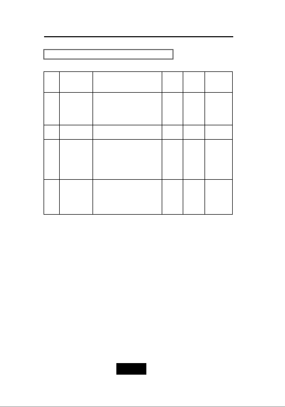
SSuummmmaarryy CCoommpprriissoonn ooff RRAAIIDD LLeevveellss
RAID
Level
Common
Name
Description
Array’s
Capcit
y
Data
Reliabiity
Data
Trasfer
Capacity
0
Disk
Striping
Data distributed across the
disks in the array.
No redundant infromation
provided.
(N)
disks
Low Ver y
High
1 Mirroring All data Dulicated 1 * disk
Ver y
High
High
3
Parallel
Transfer
Disks with
Parity
Data sector is subdivided
and distributed across all
data disk. Redundant
information stored on a
dicated partiy disk
(N-1)
disks
Ver y
High
Highest
of all
listed
alternatives
5
Independent
Access Array
with Rotating
Paridy
Data sectors are distributed
as with disk striping,
redundant information is
interspersed with user data.
(N-1)
disks
Ver y
High
Ver y
High
Page 18
1-111
Introduction
RAID
Level
Function
Description
Drives required
Min. Max.
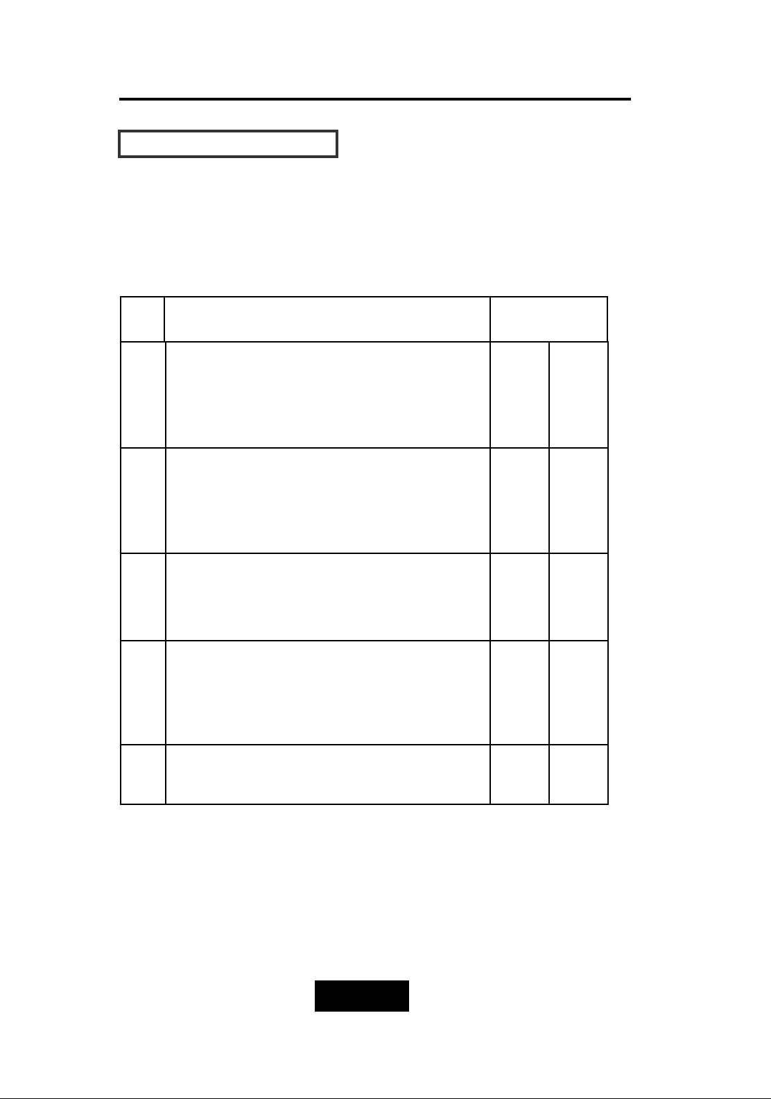
Based on the needs of a Disk Array’s capacity, data availability,
and overall performance, you can select a proper RAID level for
your Disk Array. The supported RAID levels are shown in below:
0
“Disk Striping”, block striping is used, which
yields higher performance than with the
individual disk drives.
* There is no redundant function.
2 8
1
“DIsk Mirroring”. Disk drives are mirrored,
all data is 100% duplicated on each
equivalent disk drives.
* High Data Reliability
2 8
3
“Parallel Transfer Disks with parity”. Data is
striped across physical drives. parity
protection is used for data redundancy.
3 8
5
“Independent Access Array with Parity”.
Data is striped across physical drives.
Rotating parity protection is used for data
redundancy.
3 8
0+1 “Disk Striping” + “Disk Mirroring” Function 4 8
SSuuppppoorrtteedd RRAAIIDD LLeevveellss
Page 19
1-112
Introduction
MMuullttii-SSCCSSII FFoorrmmaatt ssuuppppoorrtt
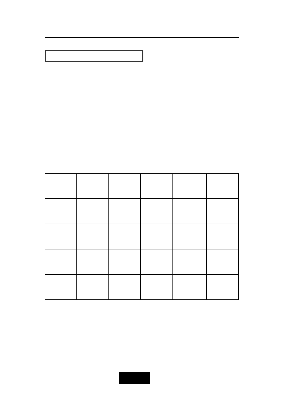
The Disk Array provides one LVD Ultra 160 SCSI channel for
connecting to your host system. With proper cabling, it may support
Narrow or Wide; Standard, Fast or Ultra SCSI formats. ( single
ended )
Overall cable length
For secure data transfer , please refer to the cable length limitations
as below :
* Cable length = External Host cables length + Internal Host cable
length
* Standard Disk Array External cable length = 90cm ( 3 ft )
* Standard Disk Array Internal cable length = 20cm
SCSI
Type
Clock
Rate
Data
Rate
Maximu
Cable
Length
Cable
Required
Remark
Ultra 160
(16 bit)
40
MHZ
160
MB/sec
12m HPD 68—
HPD 68 pin
LVD
Ultra 2
(16 bit)
40
MHZ
80
MB/sec
12m HPD 68—
HPD 68 pin
Ultra
wide
(16 bit)
20
MHZ
40
MB/sec
1.5m HPD 68—
HPD 68 pin
Ultra
SCSI
(8 bit)
20
MHZ
20
MB/sec
1.5m HPD 68—
HPD 50 pin
Page 20
2-11
Getting Started
Chapter 2: “Getting Started”
GGeenneerraall OOvveerrvviieeww
This chapter helps you get ready to use the Disk Array. It gives you:
Unpacking & Checklist
Choosing a place for Disk Array
Identifying Parts of Disk Array
Power Source
Installing the Hard Disk Drives
Setup active terminator
Host Linkage
Power-On and Self-test
LED Display and Function Keys
LCD Status Display
Clear beeper
The following illustrations will help you read the further sections.
SSppeecciiaall NNoottee::
RAID should never be considered a replacement for doing regular
backup. It’s highly recommended to conduct a backup strategy
for critical data.
Page 21
2-22
Getting Started
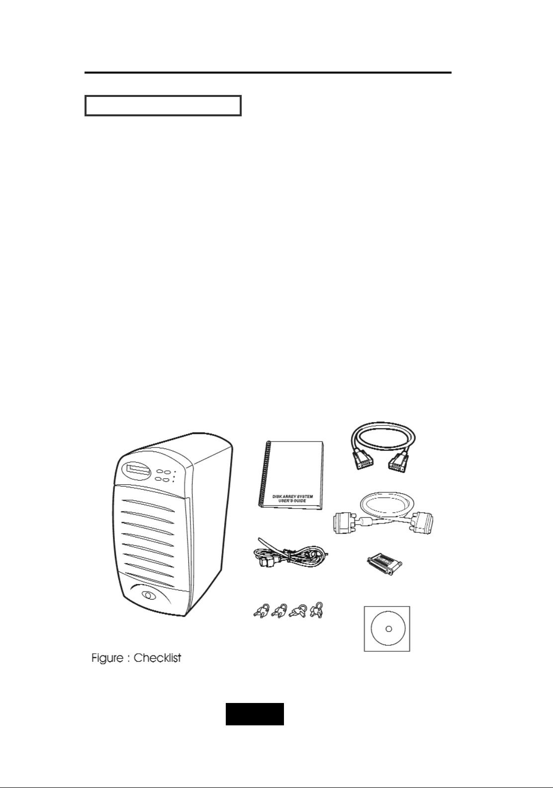
UUnnppaacckkiinngg && CChheecckklliisstt
Before unpacking your Disk Array , prepare a clean and stable
place to put the contents of your Disk Array’s shipping container on.
Altogether, you should find the following items in the package :
The Disk Array
One AC power cord
One External SCSI cable
Keys ( For HDD Trays )
User’s Guide
RS-232 Cable
Active Terminator
Global-Eyes CD
Remove all the items from the carton. If anything is missing or
broken , please inform your dealer immediately. Save the cartons
and packing materials that came with the Disk Array. Use these
materials for shipping or transporting the Disk Array.
Page 22
2-33
Getting Started
CChhoooossiinngg aa ppllaaccee ffoorr DDiisskk AArrrraayy
When selecting a place to set up your Disk Array, be sure to follow
the guidelines as below:
Place on a flat and stable surface.
Use a stand that supports at least 50 kgs for this Disk Array.
(HDD included )
Place the Disk Array close enough to the computer for the Disk
Array’s External cable to reach it.
Use a grounded wall outlet.
Avoid an electrical outlet controlled by wall switches or
automatic timers. Accidental disruption of the power source
may wipe out data in the memory of your computer or Disk
Array.
Keep the entire system away from potential sources of
electromagnetic interference, such as loudspeakers , cordless
telephones, etc.
Caution !
Avoid direct sunlight, excessive heat, moisture, or dust.
Page 23
2-44
Getting Started
IIddeennttiiffyyiinngg PPaarrttss ooff tthhee DDiisskk AArrrraayy
FFrroonntt VViieeww
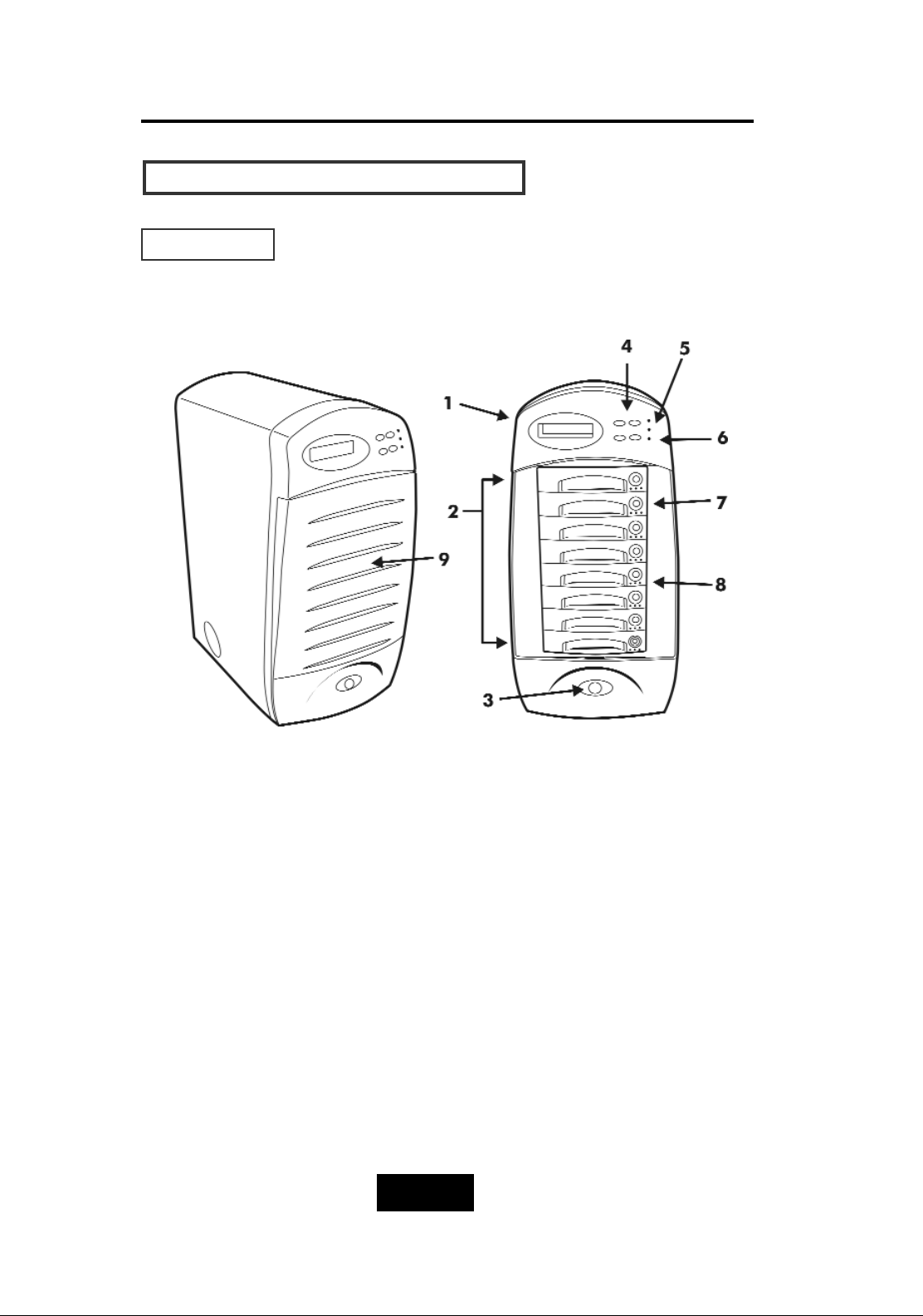
Figure : Front View
1. LCD Status Display Panel
2. HDD Trays 1 ~ 8
3. Power Supply State Indicator (light up Green / Red)
4. Function Keys (, Enter , ESC )
5. Power-On Indicator (PWR Unit 1, PWR Unit 2)
6. Host Computer Access Indicator
7. HDD Tray Lock ( Lock / Unlock )
8. HDD Status Indicator
( From left to right: Error (Red), Access (Yellow), Power-On (Green) )
9. Front Cover
Page 24
2-55
Getting Started
RReeaarr VViieeww
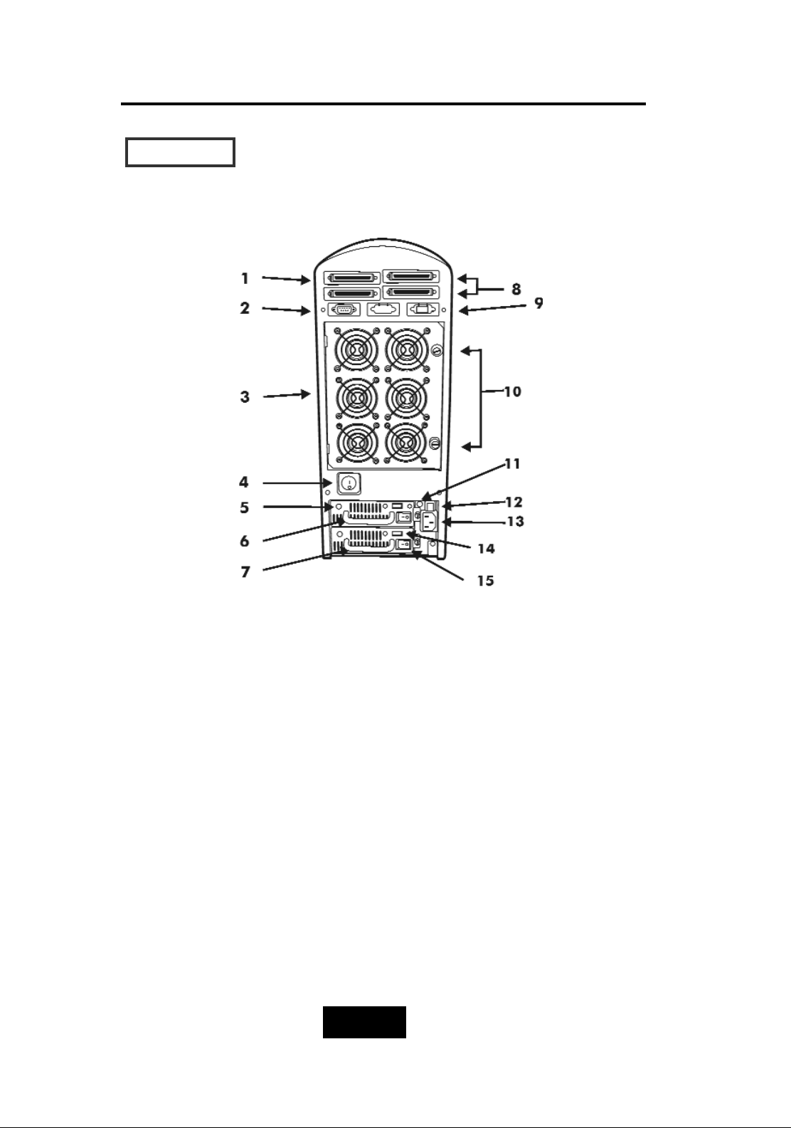
Figure : Rear View
1. Host channel adapter Port
2. RS232 Adapter ( VT100 Terminal Port )
3. Cooling Fans
4. Power Supply Unit Switch (On / Off)
5. Power Supply Unit 1 LED indicator (Green)
6. Power Supply Unit 1 (Upper)
7. Power Supply Unit 2 (Lower)
8. 2nd Host Channel Port
9. RJ45 Adapter (Terminal port for Global-Net)
10. Fan Door Screws
11. Power Supply fail indicator (Red)
12. Power Supply Alarm reset Switch
13. AC Power Source Input Socket
14. AC Voltage Select Switch ( 115V / 230V )
15. Power Supply Unit Switch (On/Off)
Page 25
2-66
Getting Started
PPoowweerr SSoouurrccee
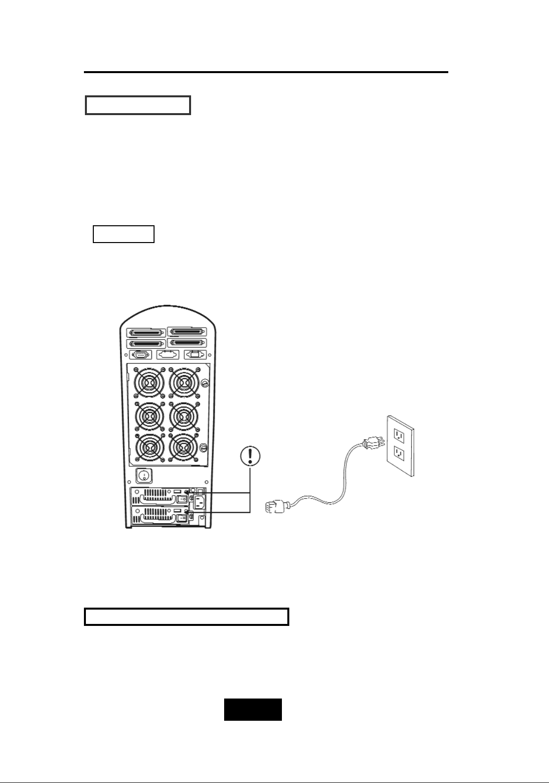
Choosing a Working Voltage
The system can run either on AC 115V (+/10%) or AC 230V(+/10%),
Slide the AC voltage select switch on the power supply to the
correct position which corresponds with the wall outlet supply
voltage.
Wrong AC Voltage input will harm the power supply and cause
serious damage to the Disk Array.
Figure : Power Source
This Disk Array is supplied with an AC power cord equipped with a
3-wwire grounding type plug. This is a safety feature and it is
important to only use a 3-wwire grounded mains power cord.
! This Disk Array must be grounded
Warning !
Page 26
2-77
Getting Started
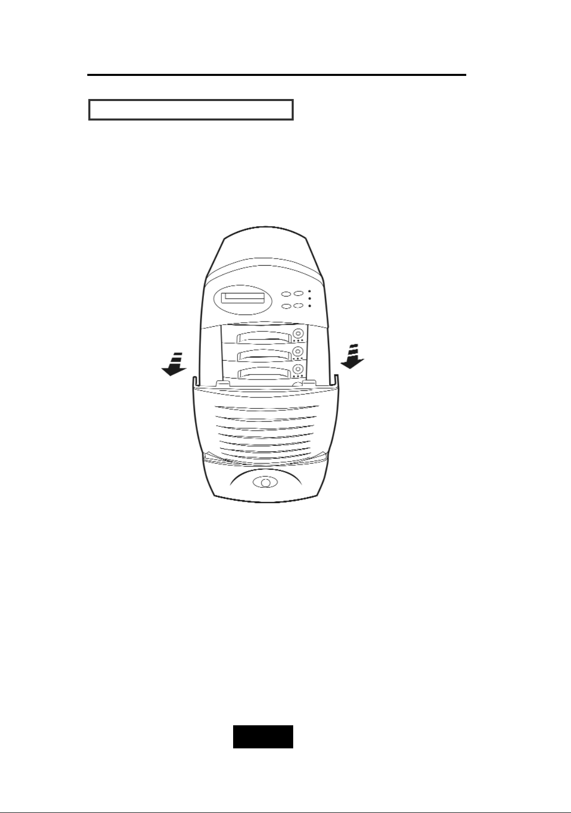
IInnssttaalllliinngg tthhee HHaarrdd DDiisskk DDrriivveess
Step 1 : Open the front cover.
Figure: Installing HDD step 1
Page 27
2-88
Getting Started
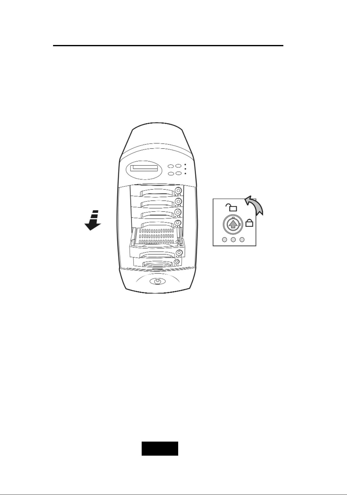
Step 2 : Unlock the HDD tray by turning the Key-lock to the correct
position.
Step 3 : Gently Pull out the HDD tray.
Figure: Installing HDD step 2, 3
Page 28
2-99
Getting Started
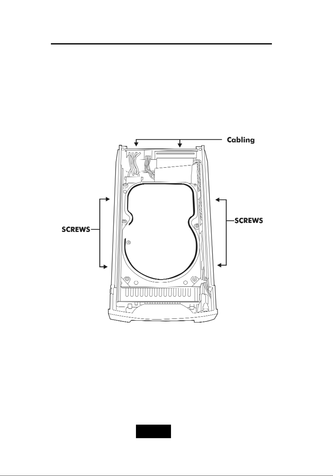
Step 4 : Insert HDD into the tray
Step 5 : Screw in the hard drive.
( Use the correct size, type and thread )
Step 6 : Cabling, Connect the Data cable and Power cable.
Figure: Installing HDD step 4, 5, 6
Page 29
2-110
Getting Started
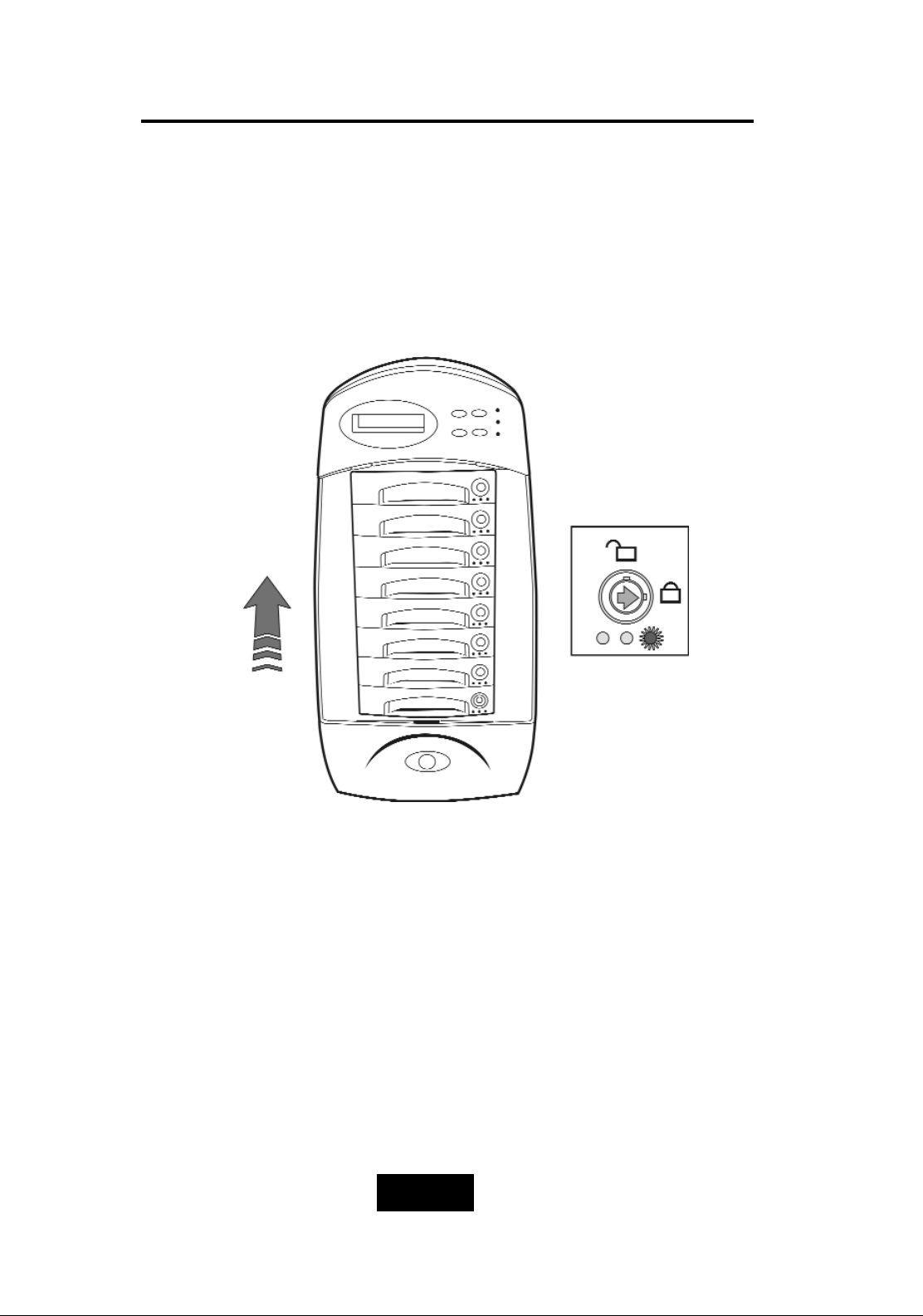
Step 7 : Gently slide in the HDD tray.
Step 8 : Lock the HDD tray. When powered on, the Green LED will
light up.
Figure:Installing HDD step 7, 8
Page 30
2-111
Getting Started
HHooww ttoo SSeettuupp AAccttiivvee TTeerrmmiinnaattoorr
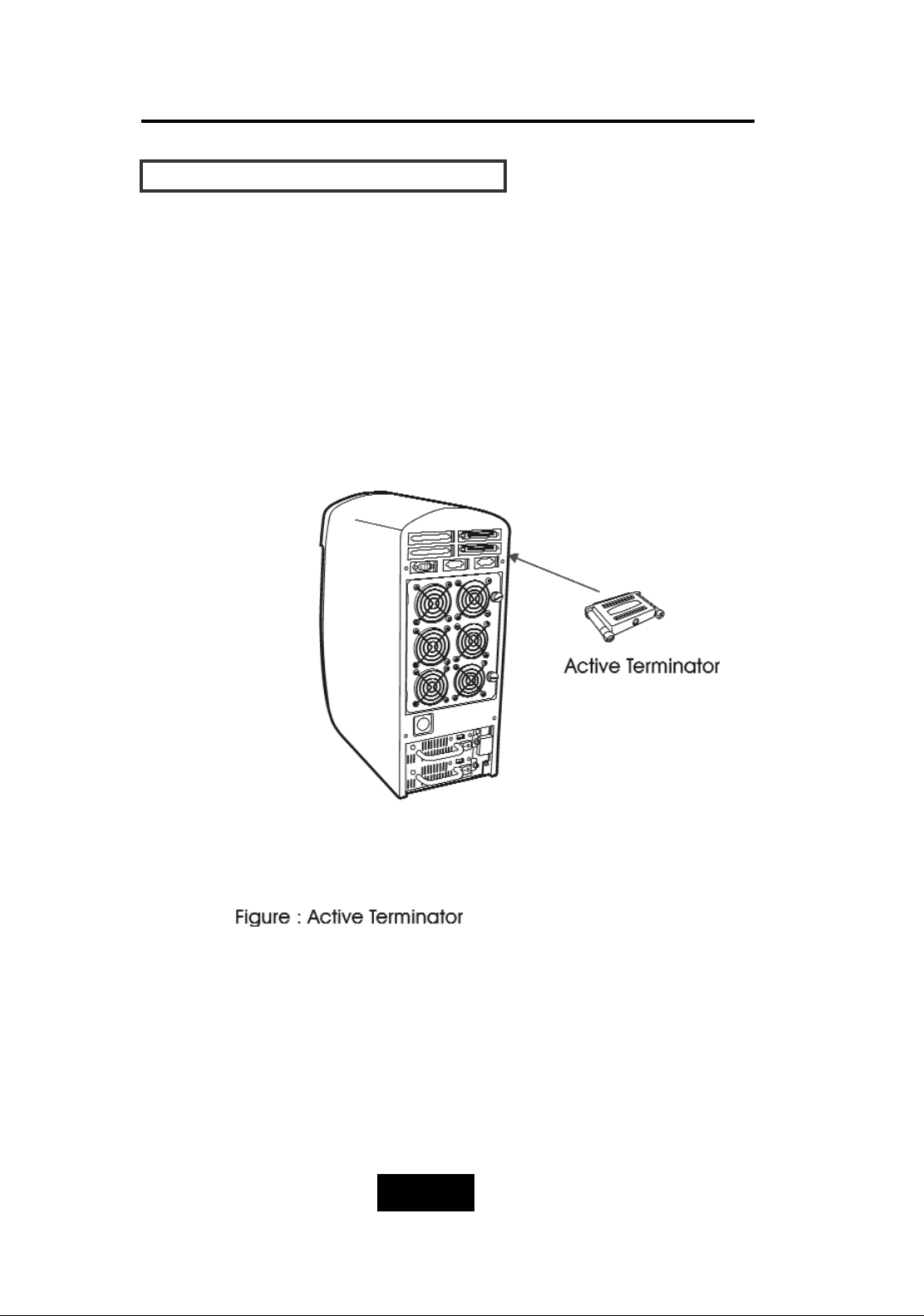
For better data integrity, we suggest you always add an active
terminator on the Disk Array when it is at the end of the SCSI bus..
PPlluugg-iinn tthhee TTeerrmmiinnaattoorr bbeeffoorree PPoowweerr-OOnn ::
You can find two ports for the host channel adapter on the back of
Disk Array. You can connect the top one with your Host Computer,
and plug in the active terminator on the second one.
Page 31
2-112
Getting Started
HHoosstt LLiinnkkaaggee
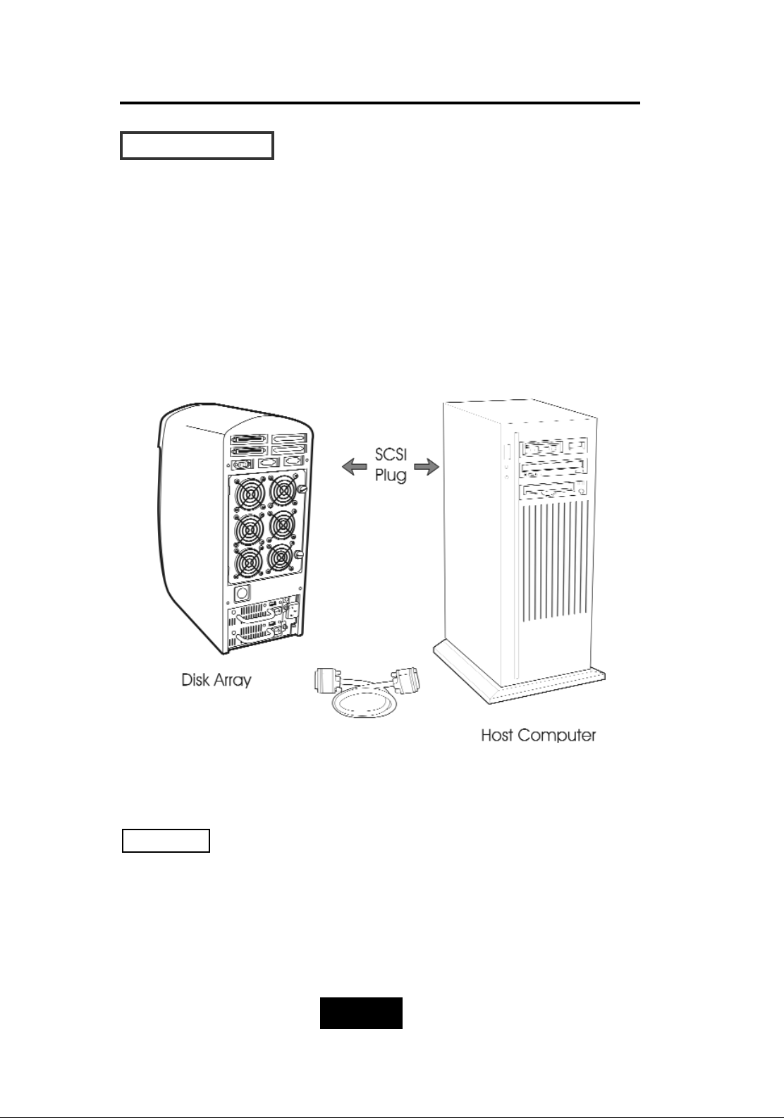
With the HDD(s) installed correctly, you are ready to connect the
Disk Array to your Host computer.
Use a External SCSI cable to connect your Host computer to the
Disk Array’s built-in SCSI adapter port.
Connect the Host computer as shown below :
Figure : Host linkage
For safety reasons, make sure the Disk Array and Host Computer
are turned off when you plug-iin the SCSI cable.
Caution !
Page 32
2-113
Getting Started
PPoowweerr-oonn aanndd SSeellff-TTeesstt
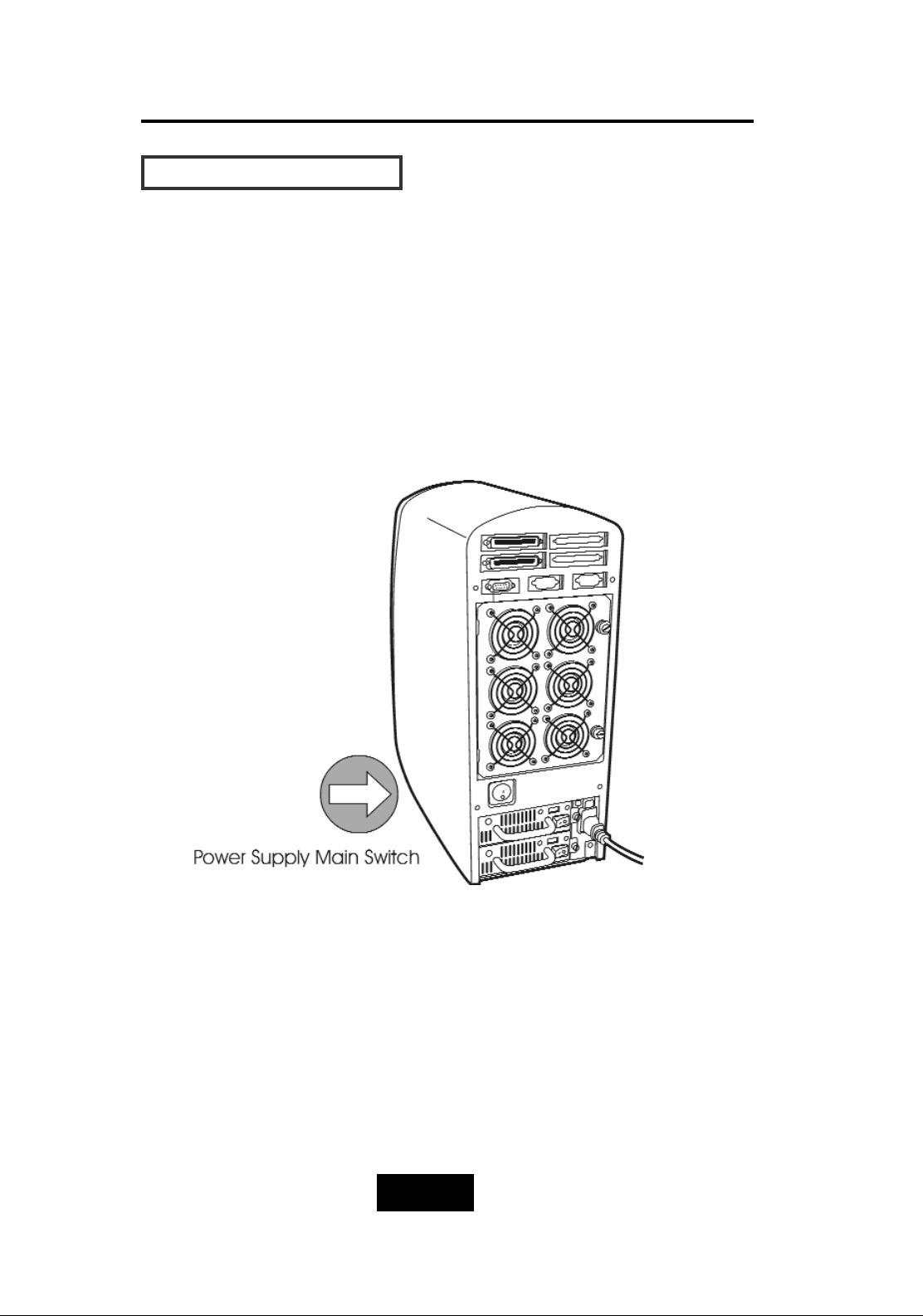
When you connect the Disk Array to the Host computer, You
should press the ON/OFF Power Supply Switch on both of the power
supply Hot-Swap units and the Main Switch. It will turn the Disk Array
on and the Self-Test will be started
Figure:Power-On & Self-Test
Page 33
2-114
Getting Started
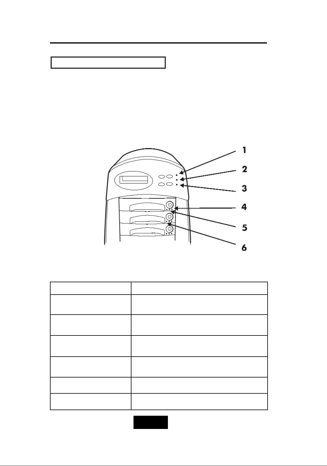
LLEEDD DDiissppllaayy && FFuunnccttiioonn KKeeyyss
LLEEDD DDiissppllaayy
Shown below is the LED Display. Please refer to the illustration, the
LEDs inform you of the Disk Array’s current operating status. Upon
activating a certain function, the corresponding LED indicator
should turn on indicating that the feature is engaged.
LED Description
1. Power Unit 1 Indicator light up:
“Green”
, it lights when the power Unit 1 is
plugged and operating functionally.
2. Power Unit 2 Indicator light up:
“Green”
, it lights when the power Unit 2 is
plugged and operating functionally.
3. Host Computer Access
Indicator
light up:
“Yellow”
indicates Host computer is curretnly
accessing the Disk Array
4. HDD Power-On Indicator
light up:
“Green”
, it lights when the HDD frame is
locked and Power-on.
5. HDD Access Indicator light up:
“Yellow”
, when HDD is accessed
6. HDD Error Indicator light up:
“Red
, when the HDD not installed or error
Figure:LED Display
Page 34
2-115
Getting Started
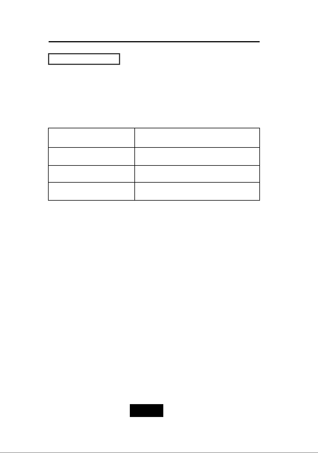
FFuunnccttiioonn KKeeyyss
The four function keys at the top of the front panel perform the
following functions:
() Up Arrow / Right Arrow
Use to scroll the cursor Upward / Rightward
() Down Arrow / Left Arrow
Use to scroll the cursor Downward / Leftward
(Enter) Use to confirm a selected item
(ESC) Use to exit a selection
Page 35
2-116
Getting Started
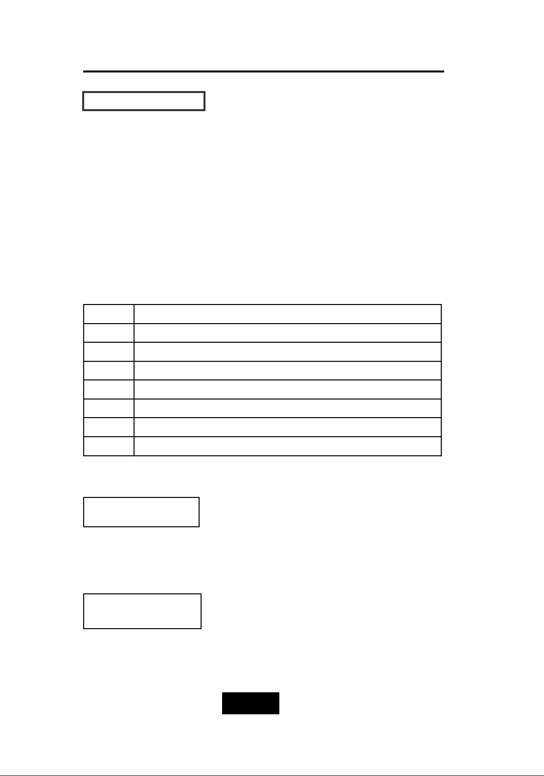
LLCCDD SSttaattuuss PPaanneell
Located the LCD panel, the LCD status panel informs you of the
Disk Array’s current operating status at a glance. Upon activating a
certain function, a symbol or icon corresponding to that function
will appear in the display window. The symbol will remain in the
display window indicating the status of the Disk Array.
IIddeennttiiffyyiinngg tthhee ssttaattuuss oonn tthhee LLCCDD
The following illustration shows the symbols (characters) been used
and their representation.
A description of each of the symbols in LCD display window :
Example of the LCD status display window :
This informs you :
a. HDD 1 ~ HDD 3 : On-line (RAID Group1)
b. HDD 4 ~ HDD 6 : On-line (RAID Group2)
c. HDD 7 : It is a Spare disk drive
d. HDD 8 : Not installed
11 11 11 22 22 22 SS XX
R Error occur (Fault)
I Identifying Disk Drive
S Spare Disk Drive
X Disk Drive not installed
W Warning: Disk Drive with too many Bad Sectors
A Add new Disk Drive when On-Line Expansion
J
JBOD Configuration
1/2/3/4 RAID Group 1/2/3/4
This informs you :
a. RAID 1 : RAID Group1
b. R5 : RAID Level 5
c. 12345 : HDD No. 1, 2, 3, 4, 5 in RAID1
members
RAID1 R5
11 22 33 44 55
Page 36
2-117
Getting Started
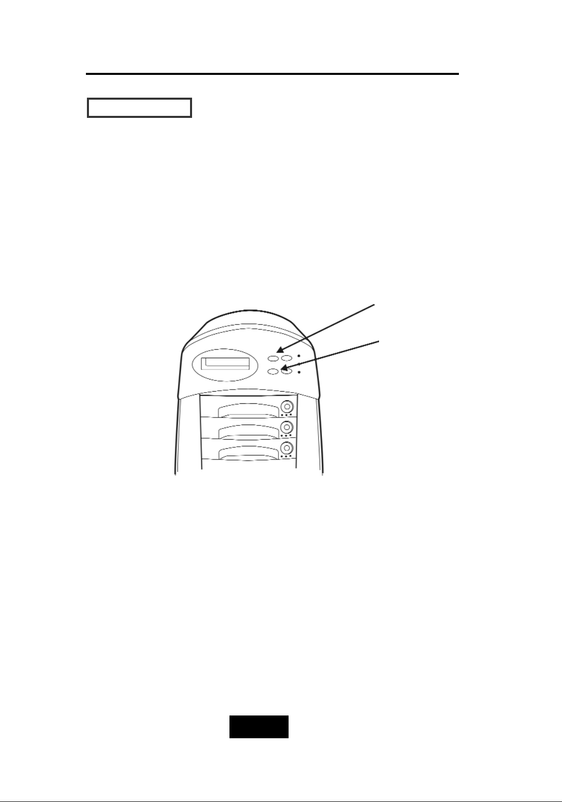
Clear Beeper
The disk drive initialization and fail beeping can be stopped
by pushing the
() and
()
simultaneously twice. But you should
remember to replace the drive. Next time when error happen the
beeping will still be available.
()
(
)
Page 37
Configuration
3-11
After completing the hardware installation, the disk array must be
configured and the logical unit must be initialized before it is ready
to use. This can be accomplished through the following user
interfaces :
Front Panel function keys ( LCD Display )
or
VT100 terminal connected through the serial port ( Monitor Port)
or
The GUI S/W (Graphical User Interface). Defails please refer to the
Global-Eyes CD-Rom.
The LCD display panel and a VT100 terminal can not be used
at the same time.
This chapter guides you through setting up your Disk Array for the
first time. This chapter contains information on setup. The setup
program is a menu-driven utility which enables you to make
changes to the configuration and tailor your Disk Array to your
individual needs.
The setup program is a ROM-based configuration utility which
displays the Disk Array’s status and allows you to set up the
parameters. The parameters are stored in a nonvolatile battery
backup CMOS RAM which saves the information even when the
power is off.
By using an easy-to-use user interface, you can configure such
items as :
RAID Level
Hot Spare Disk
SCSI ID
Password ( For protection from unauthorized use )
Firmware update (VT100 Terminal mode only) —- for update
procedures please refer to Chapter 4 : Advanced information.
The setup program has been designed to make it as easy to use
as possible. By using a menu-driven program, you can scroll
through the various sub-menus and make your selections among
the various predetermined choices.
Chapter 3: “Configuration”
Page 38
Configuration
3-22
CCoonnffiigguurraattiioonn ffrroomm tthhee ffrroonntt PPaanneell
The LCD Display front panel function keys are the primary user
interface for the Disk Array. Except for the “Firmware update” ,all
configuration can be performed through this interface.
Function Key Definitions
The four function keys at the top of the front panel perform the
following functions :
() Up Arrow / Right Arrow
Use to scroll the cursor Upward / Rightward
() Down Arrow / Left Arrow Use to scroll the cursor Downward / Leftward
(
Enter
)
Use to confirm a selected item
(
ESC
) Use to exit a selection
Page 39
Configuration
3-33
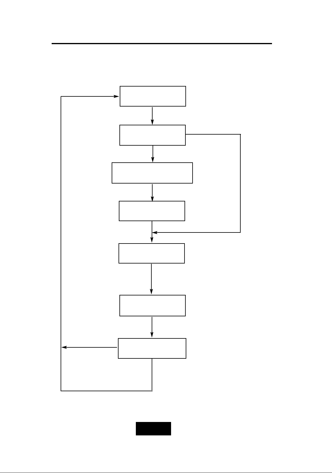
CCoonnffiigguurraattiioonn pprroocceedduurreess ((vviiaa FFrroonntt PPaanneell))
Main screen
RAID Level
(0,1,3,5,0+1,None)
Re-Config RAID
Hot Spare Disk
(Yes / No)
Set Password
(4 Digital)
Save Configuration
& Restart
Yes
No
Yes
No
Set SCSI ID
( 0~14 )
Page 40
Configuration
3-44
SSttaarrttiinngg tthhee ccoonnffiigguurraattiioonn
1. Power-on the Disk Array. At the end of the power-on self test
program, the LCD displays the current system status. The
default setting is JBOD ( just a Bunch of Disks ).
2. Press the front panel “
Enter
“ key to access the built-in
configuration program.
3. When the screen displays the password prompt and asks you to
“ Enter Password “
press “ Enter “ 4 times to input the default password
( default password is “ 0000 “ )
4. Re-Configuration RAID
Select “ No“ to set up “SCSI ID#” ,and
“Password”.
Select “
Yes
“ to set up “ RAID Level “ , “ Hot spare disk “ , “SCSI
ID#” ,and “ Password “
Enter Password
0
Page 41
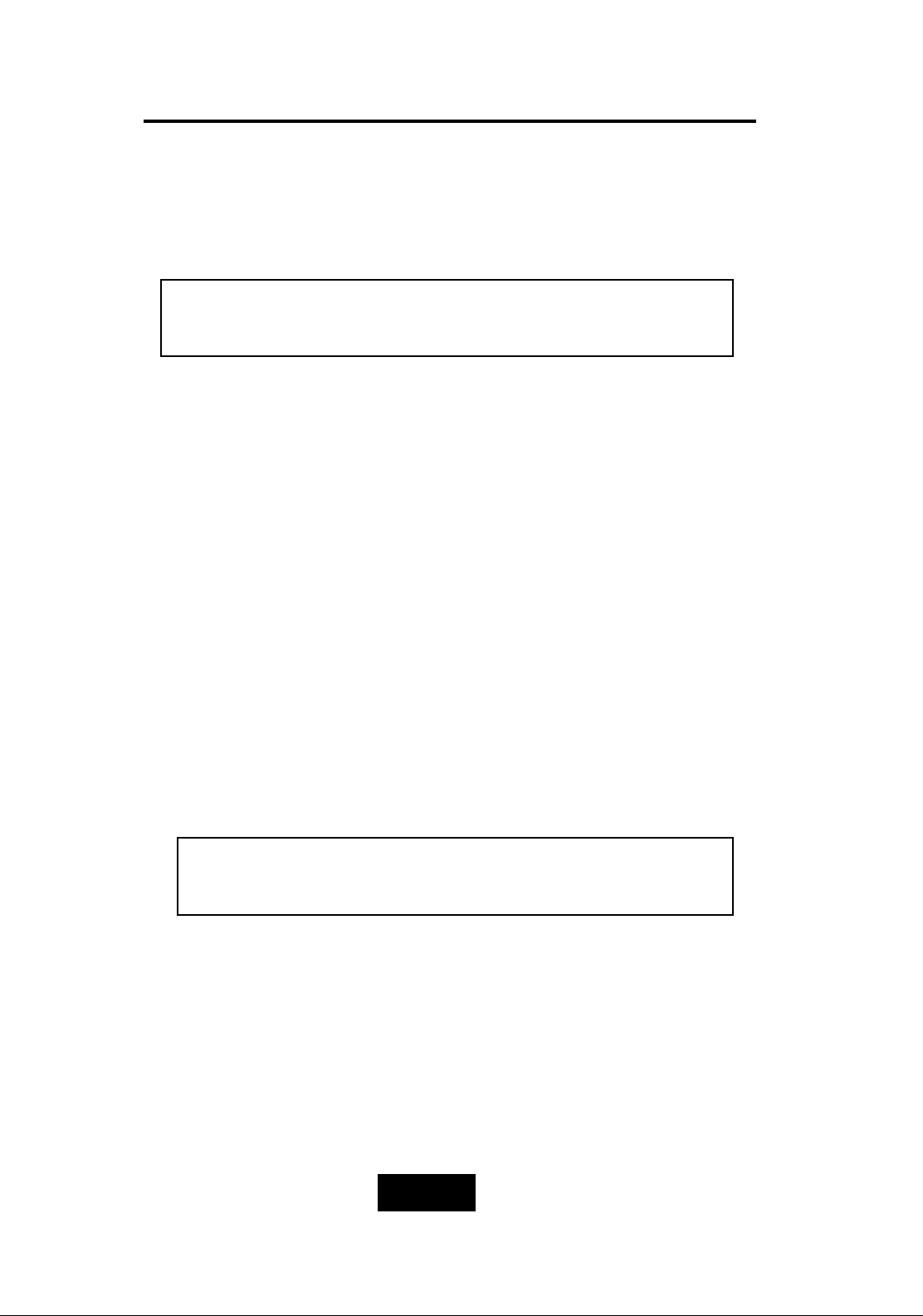
Configuration
3-55
5. Set RAID Level
Move cursor ( ) to the desired RAID Level
( 0, 1, 3, 5, 0+1,
None )
, press “
Enter
“ to confirm.
* RAID Level “
None
“ = JBOD
6. Set Hot Spare Disk
Select “
Yes
“ to set
one
Disk Drive as a Hot-spare Disk.
(Valid for RAID Level 5 and 3 , the total number of Disk Drives
installed
must be more than 3 Disk Drives
)
7. Set SCSI ID
Each device on a specific SCSI bus must be configured with a
target address ( which is a “SCSI ID” ) which is different from any
other devices on the SCSI Bus.
The default SCSI ID for the Disk Array is ID 0.
If you needed to assign a different ID # for your Disk Array. The
available SCSI ID# for this Disk Array are ID# 0 ~ 14 .
You must assign a different SCSI ID to each SCSI device
on the SCSI Bus. The SCSI ID# must be Unique for each
device.
Warning
All data on the disk drives will be lost by changing the RAID
Level.
Page 42
Configuration
3-66
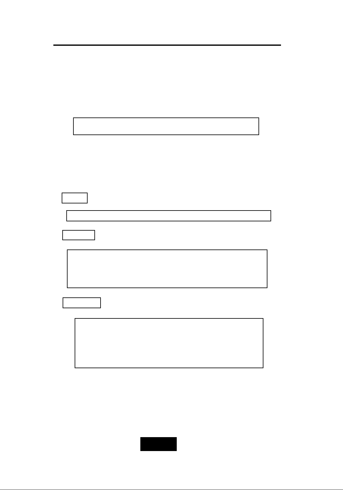
8. Set Password
Press “
Enter
“ to activate the Password setting. When the cursor
stop on the desired “number” or “character”, Using “” and
“” function keys to choose the desired characters and then
press “
Enter
“ to confirm it.
9. Save Configuration & Restart
Select the Save Configuration function and Press the “ Enter “
key to save and activate your selections.
10. The disk array will automatically partition the slice capacity
and assign LUN Number if the total capacity is over 2TB. Thus
after the system restart it will appear in the Host machine
with 2 LUNs (default LUN 0=2TB, rest capacity assign to LUN1 )
STOP
WARNING
Press “
ESC
“ function key for password “
No Change
”
Notice
Warning ! All data will be lost if you changed RAID Levels .
If you already have a RAID level setting and wish to
change to different RAID level, you must setup RAID level to
“None” first, then run the setup procedure again to setup
expected RAID level.
Saving configuration changes causes the disk array
controller’s working parameters to change. This can
produce unpredictable results if it occurs during Host
and Array activity. All activity to the controller should
be stopped before saving configuration changes.
Page 43
Configuration
3-77
CCoonnffiigguurraattiioonn ffrroomm VVTT110000 TTeerrmmiinnaall MMooddee
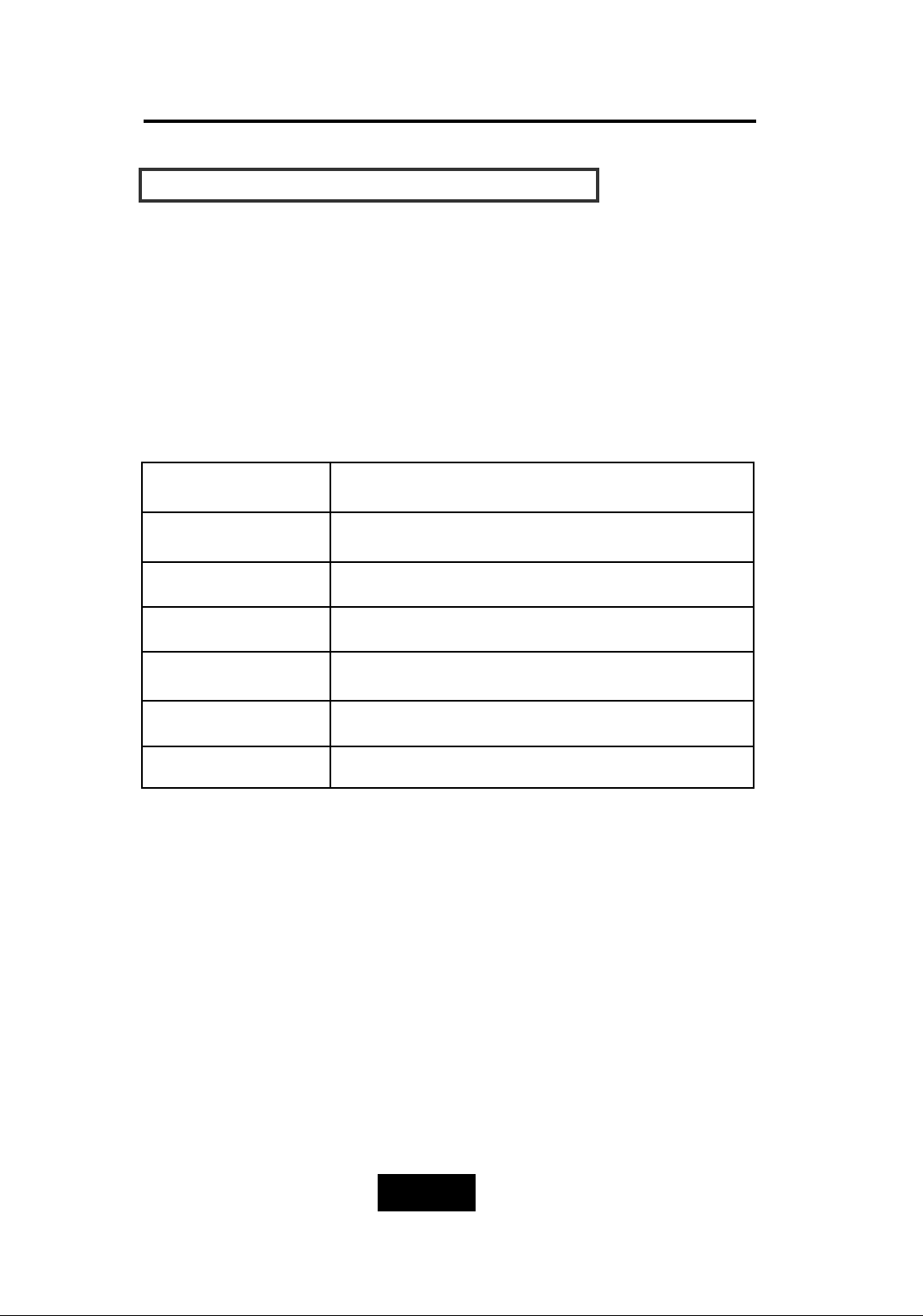
By connecting a VT100 compatible terminal or a PC operating in a
terminal emulation mode, a configuration can be performed
through this interface.
To ensure proper communications between the “Disk Array” and
the “Terminal”, Please configure the VT100 terminal settings to the
values shown below :
VT100 Terminal ( or compatible ) Set up
Connection Serial Port ( COM 1 or COM 2 )
Protocol RS232 ( Asynchronous )
Cabling Null-Modem cable
Baud Rate 115,200
Data Bits
8
Stop Bit
1
Parity None
Keyboard Function Key Definitions
“
Enter
“ key, Use to confirm a selected item
“
ESC
“ key, Use to exit a selection
“
A
“ key, Use to scroll the cursor Upward / Rightward
“ Z“ key, Use to scroll the cursor Downward / Leftward
“
Tab
“ key, Use to switch mode ( Menu / Output Area )
Page 44
3-88
configuration
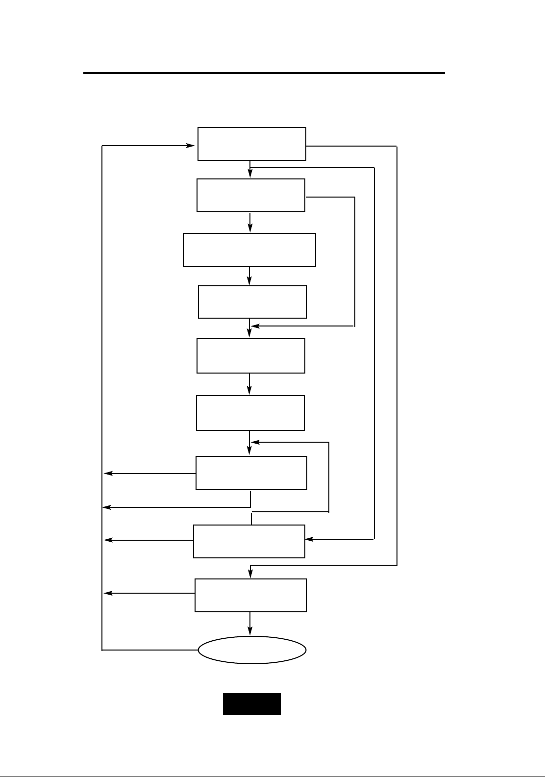
CCoonnffiigguurraattiioonn pprroocceedduurreess ((VVTT110000 TTeerrmmiinnaall))
Main screen
RAID Level
(0,1,3,5,0+1,None)
Re-Config RAID
Hot Spare Disk
(Yes / No)
Set Password
(4 Digital)
Save Configuration
& Restart
Yes
No
Yes
No
Update Firmware
Update
No
Yes
Set SCSI ID
( 0~14 )
On-Line Expand
(Enable)
Yes
No
Page 45
Configuration
3-99
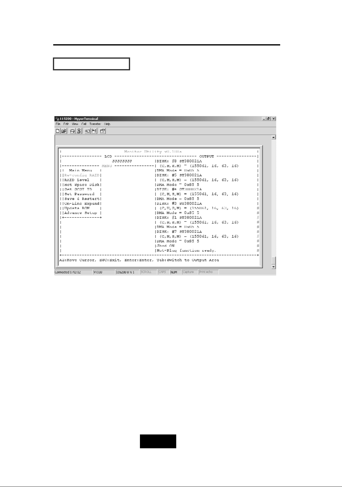
MMaaiinn SSccrreeeenn
Please refer to Chapter4 “Advanced Information” for setting VT100
Terminal in Windows.
Page 46
Configuration
3-110
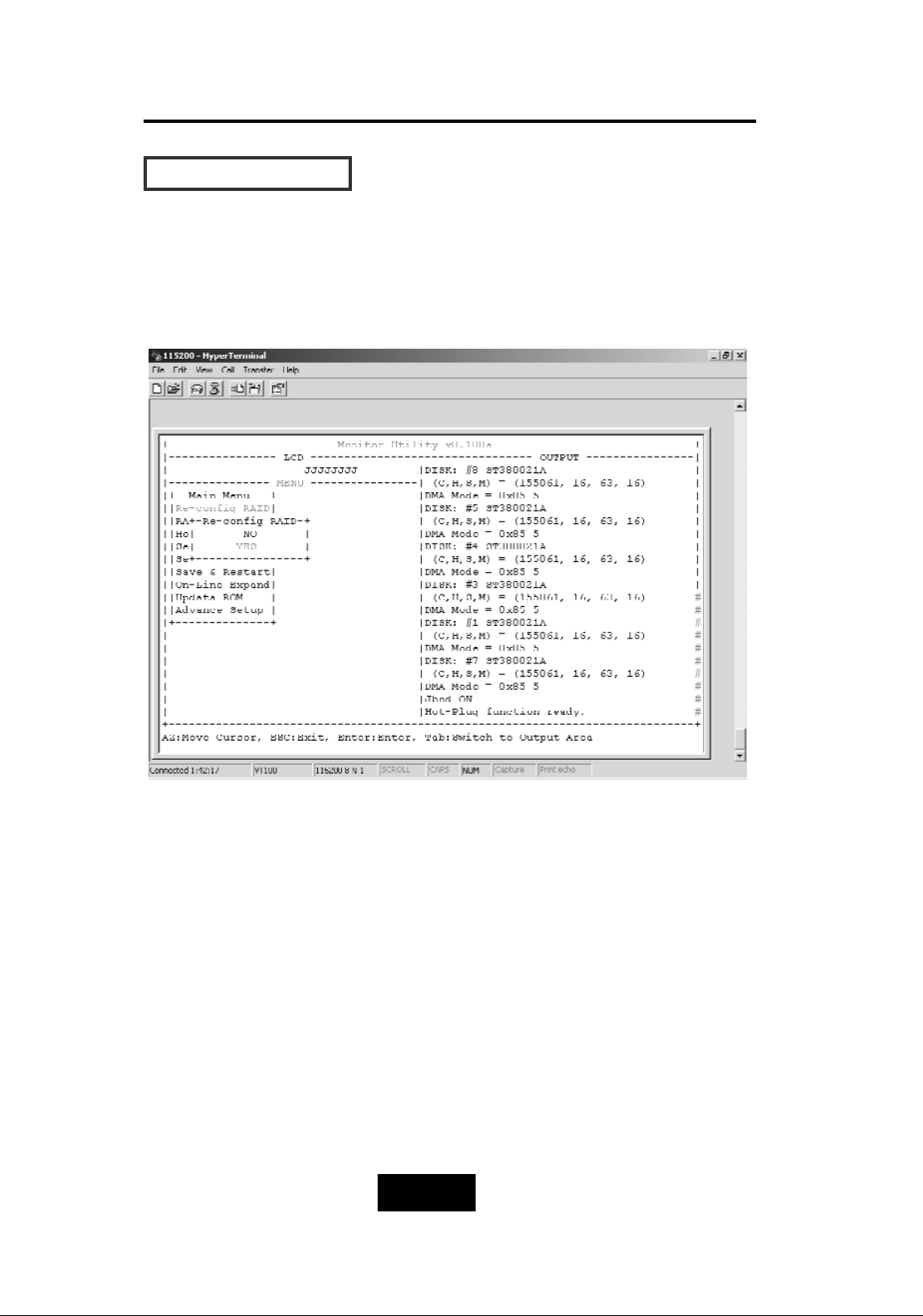
RRee-CCoonnffiigg RRAAIIDD
Select “ No” for setting : “SCSI ID” , “ Password “
Select “ Yes “ for setting all the configurations
Page 47
Configuration
3-111
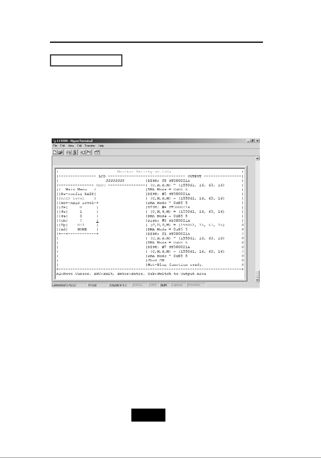
SSeett RRAAIIDD LLeevveell
Move the cursor to the desired RAID Level ( 0, 1, 3, 5, 0+1, None ),
and Press “ Enter “ to confirm it.
Warning!!
All Data will be lost by changing the RAID level.
Page 48
Configuration
3-112
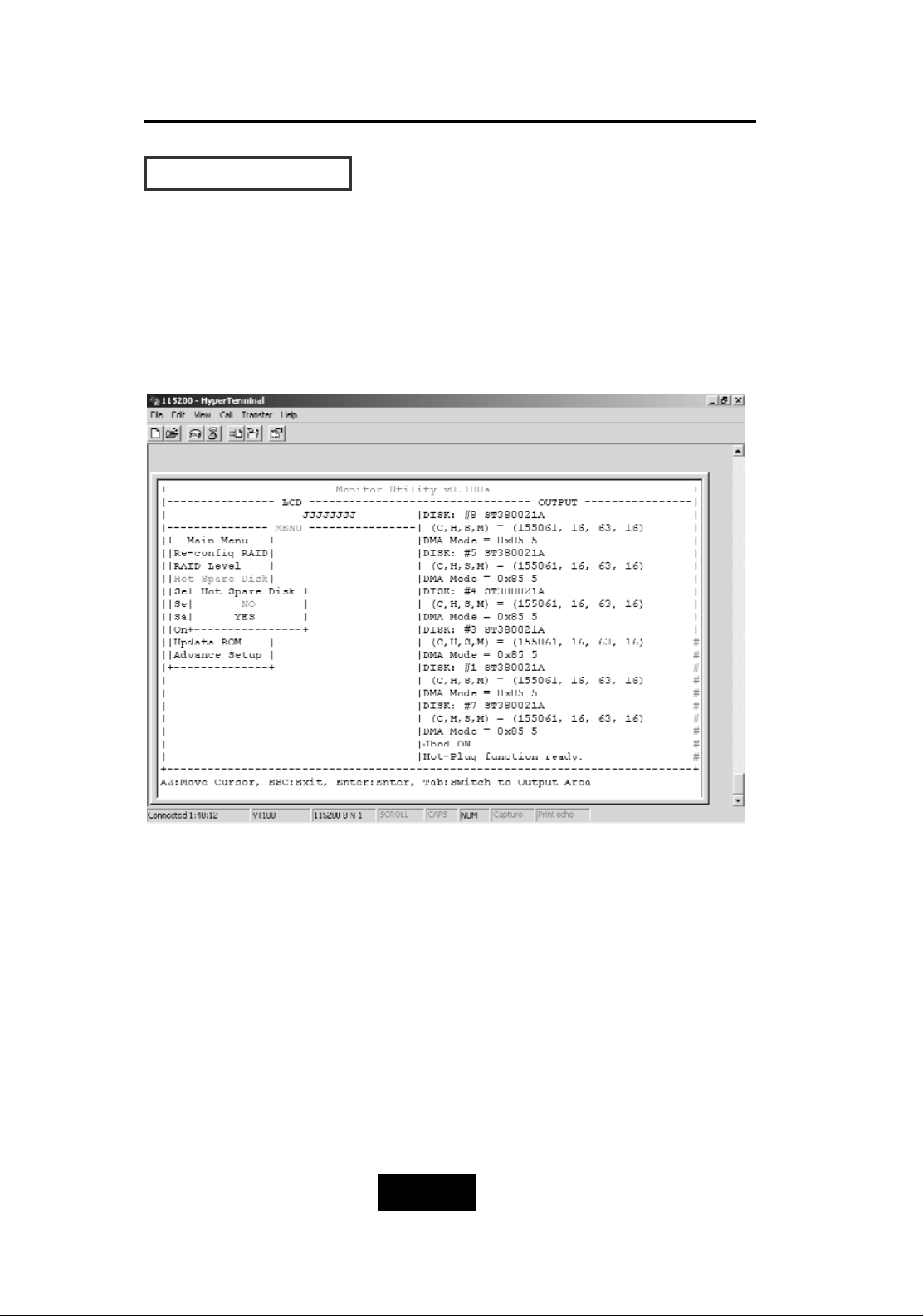
HHoott SSppaarree DDiisskk
Select “
Yes
“ to set
One Disk Drive
as a Hot Spare Disk.
This Function is
valid in RAID level 5
and
RAID level 3
, the total Disk
Drives installed must be more than 3 Disk Drives.
( Disk Drives number > 3 )
Page 49
Configuration
3-113
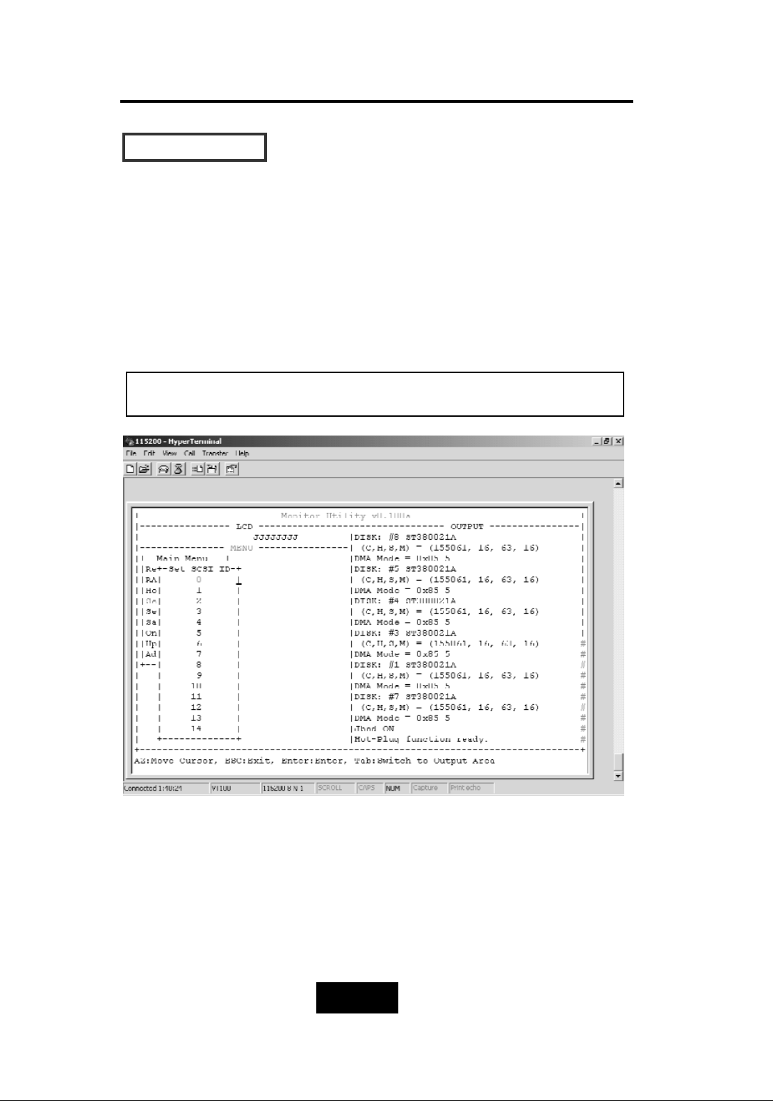
SSeett SSCCSSII IIDD##
Each device on a SCSI bus must be configured for a Target
address (which is a “SCSI ID”), which is different from any other
device on the SCSI Bus.
The default ID for this Disk Array is ID#0
If you needed to assign a different ID# for your Disk Array,
The available SCSI ID# for this Disk Array is ID# 0 ~14
You must assign a different SCSI ID to each SCSI device on the
SCSI Bus. The SCSI ID# must be unique for each device.
Page 50
Configuration
3-114
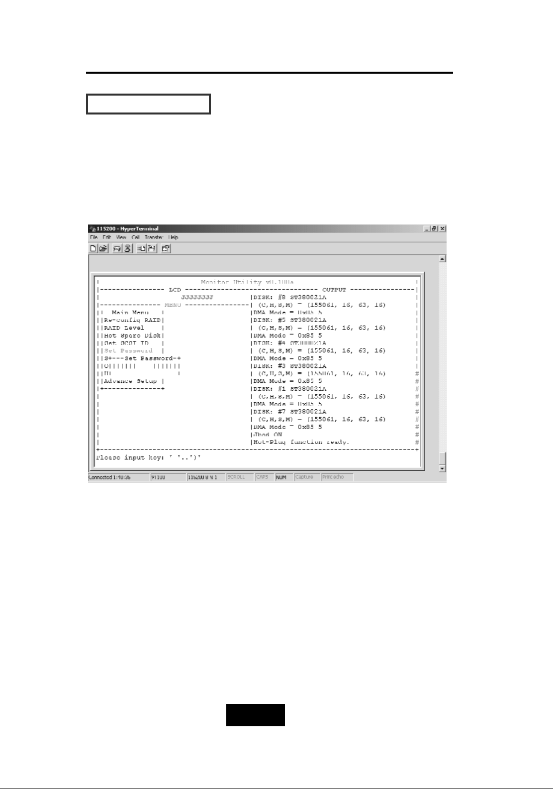
SSeett PPaasssswwoorrdd
Press “
Enter
“ to activate the password setting then to key-in the
desired “ Number “ or “ Character “.
Press “ ESC “ to skip the charge of the password.
Page 51
Configuration
3-115
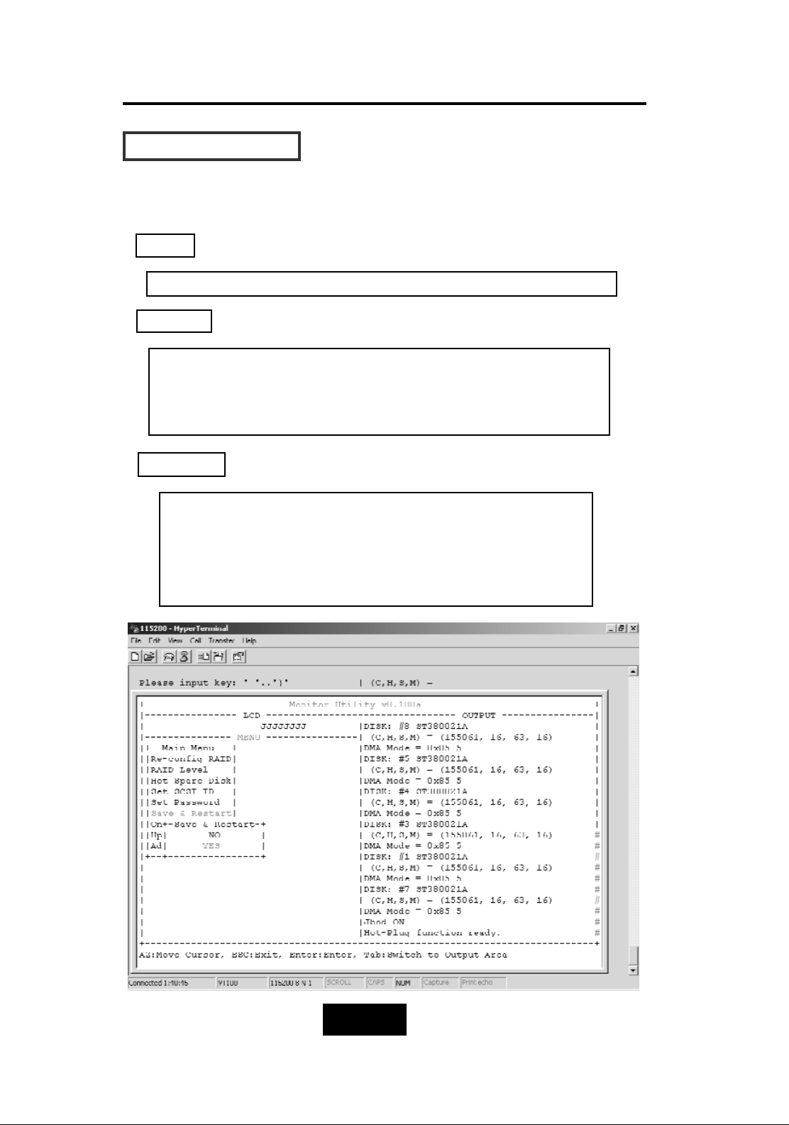
SSaavvee && RReessttaarrtt
Select the Save & Restart function and press “
Enter
” to save and
activate your selections.
STOP
WARNING
Notice
Warning ! All data will be lost if you changed RAID Levels .
If you already have a RAID level setting and wish to
change to different RAID level, you must setup RAID level to
“None” first, then run the setup procedure again to setup
expected RAID level.
Saving configuration changes causes the disk array
controller’s working parameters to change. This can
produce unpredictable results if it occurs during Host
and Array activity. All activity to the controller should
be stopped before saving configuration changes.
Page 52
Configuration
3-116
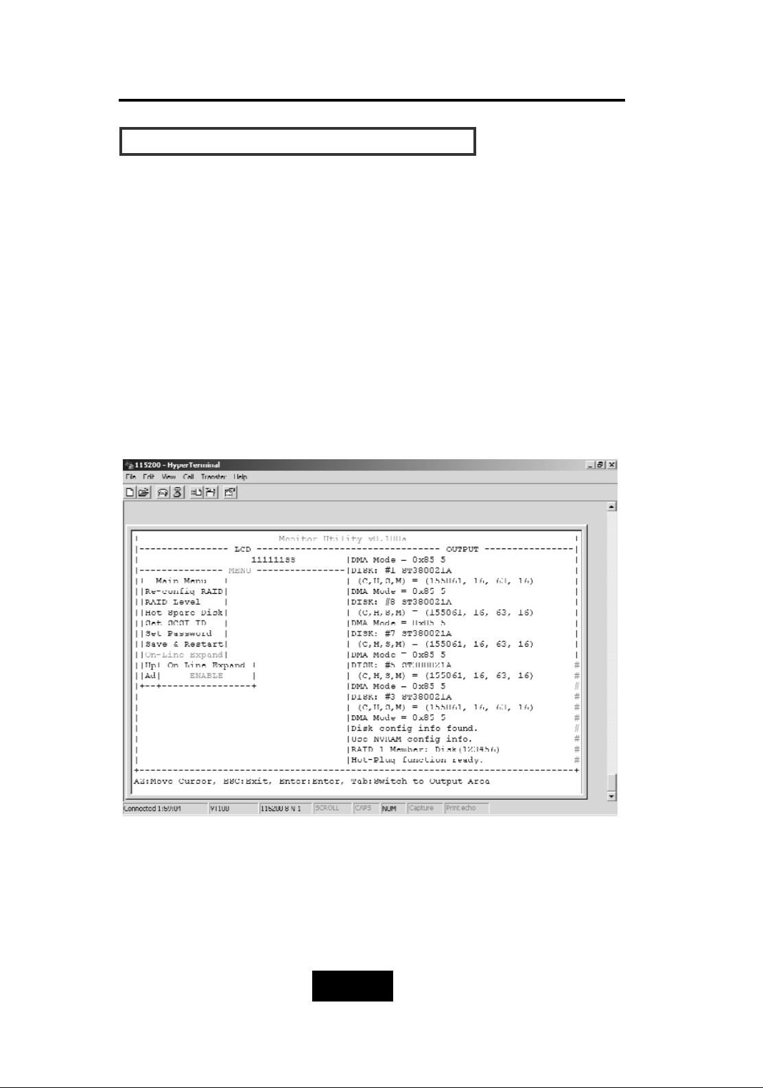
CCaappaacciittyy EExxppaannssiioonn ((FFoorr SSiinnggllee RRAAIIDD))
The RAID capacity can be expanded by adding one or more Disk
Drive into the existing RAID group and properly setup procedures.
1.Add new HDD into the RAID system.
2.Configuration through the RS-232 Terminal mode, move the cursor
to “
On-LLine Expand
” and “
Enable
” and “press “
Enter
” to confirm
it.
( If you have not add any new HDD into the RAID group the
“
Enable
” item will not show up. )
Page 53
4-11
Advanced Information
Chapter 4: “Advanced Information”
This chapter describes more advanced information about your Disk
Array. The following items are describes in detail.
Memory Expansion
RAID Controller
Updating Firmware
Multiple RAID configuration
Slice Partition and LUN Mapping
Capacity Expansion (on-line expand)
Page 54
4-22
Advanced Information
MMeemmoorryy EExxppaannssiioonn
Your Disk Array comes with 64MB of memory that is expandable
to a maximum of 512MB.
These expansion memory module can be purchased from your
dealer.
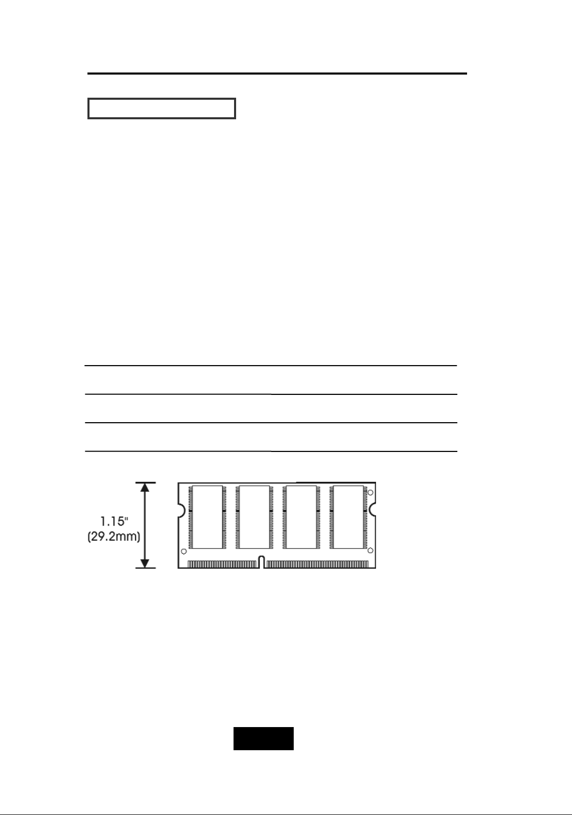
Memory Type : 3.3V PC100/133 SDRAM 144pin DIMM.
Memory Size : Supports 144pin DIMMs of 64MB, 128MB, 256MB,
or 512MB.
Height : 1.15 Inches (29.2mm).
64MB 8(8Mx8), 8(4Mx16) or 4(8Mx16)
128MB 16(8Mx8), 8(16Mx8), 8(8Mx16) or 4(16Mx16)
256MB 16(16Mx8), 8(32Mx8)
512MB 16(32Mx8)
Page 55
4-33
Advanced Information
IInnssttaalllliinngg MMeemmoorryy MMoodduulleess ::
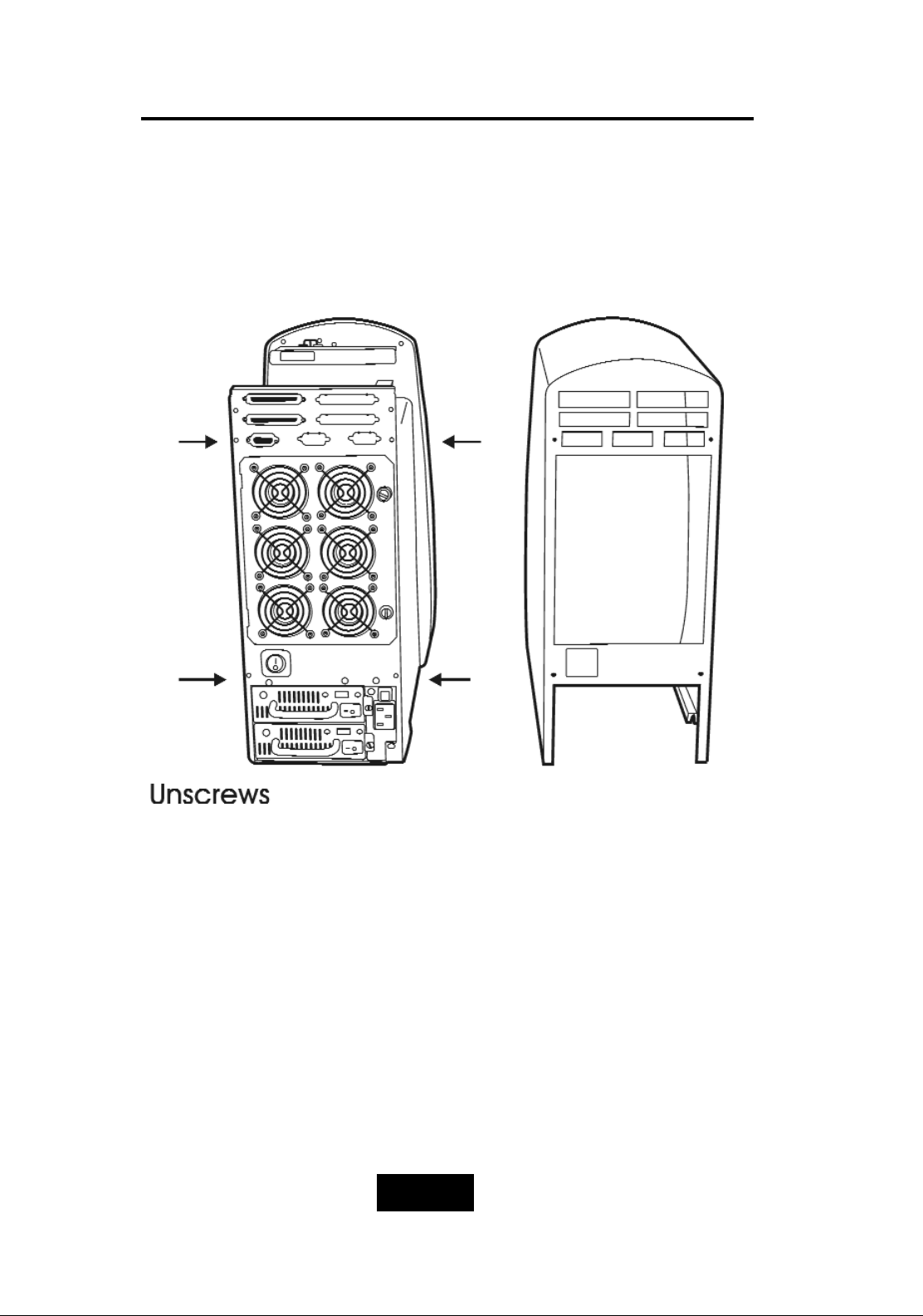
1. Unscrew & Remove cover
Figure: Remove Cover
Page 56
4-44
Advanced Information
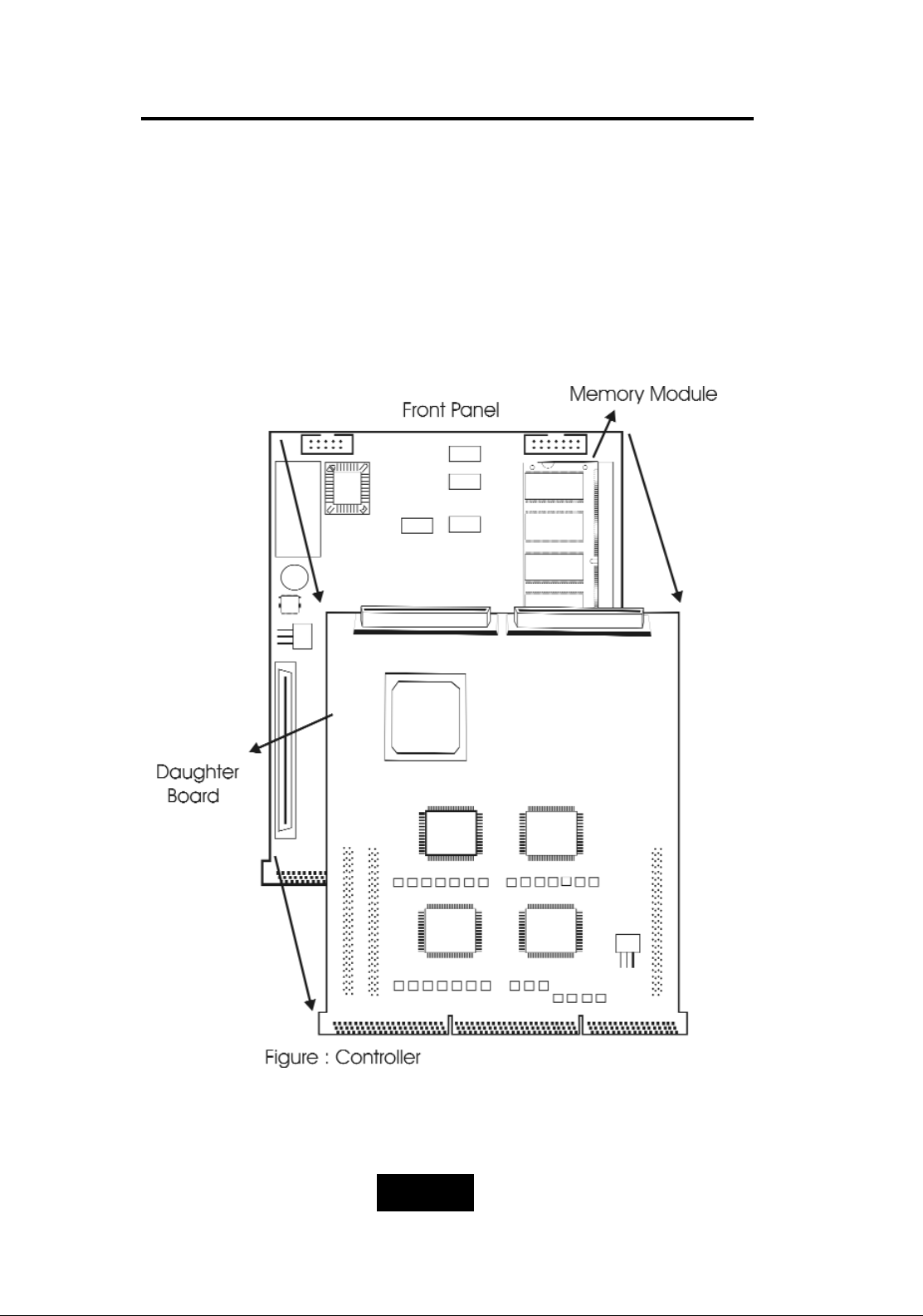
2. Install the memory
a. Remove daughter board
b. The DIMM memory modules will only fit in one orientation.
c. Press the memory module firmly into socket from a 45
degree angle, make sure that all the contacts are aligned
with the socket.
d. Push the memory module forward to a horizontal position.
Page 57
4-55
Advanced Information
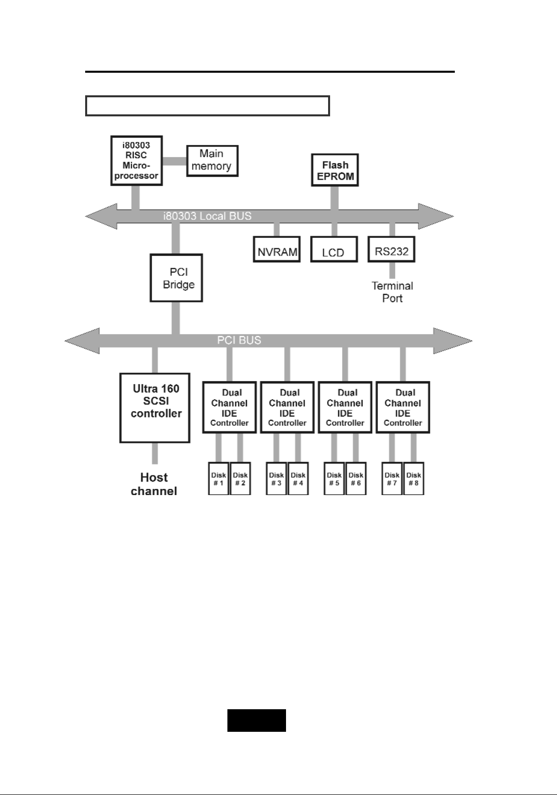
DDiisskk AArrrraayy CCoonnttrroolllleerr BBlloocckk DDiiaaggrraamm
Page 58
4-66
Advanced Information
UUppddaattiinngg FFiirrmmwwaarree
1. Setup your VT100 Terminal
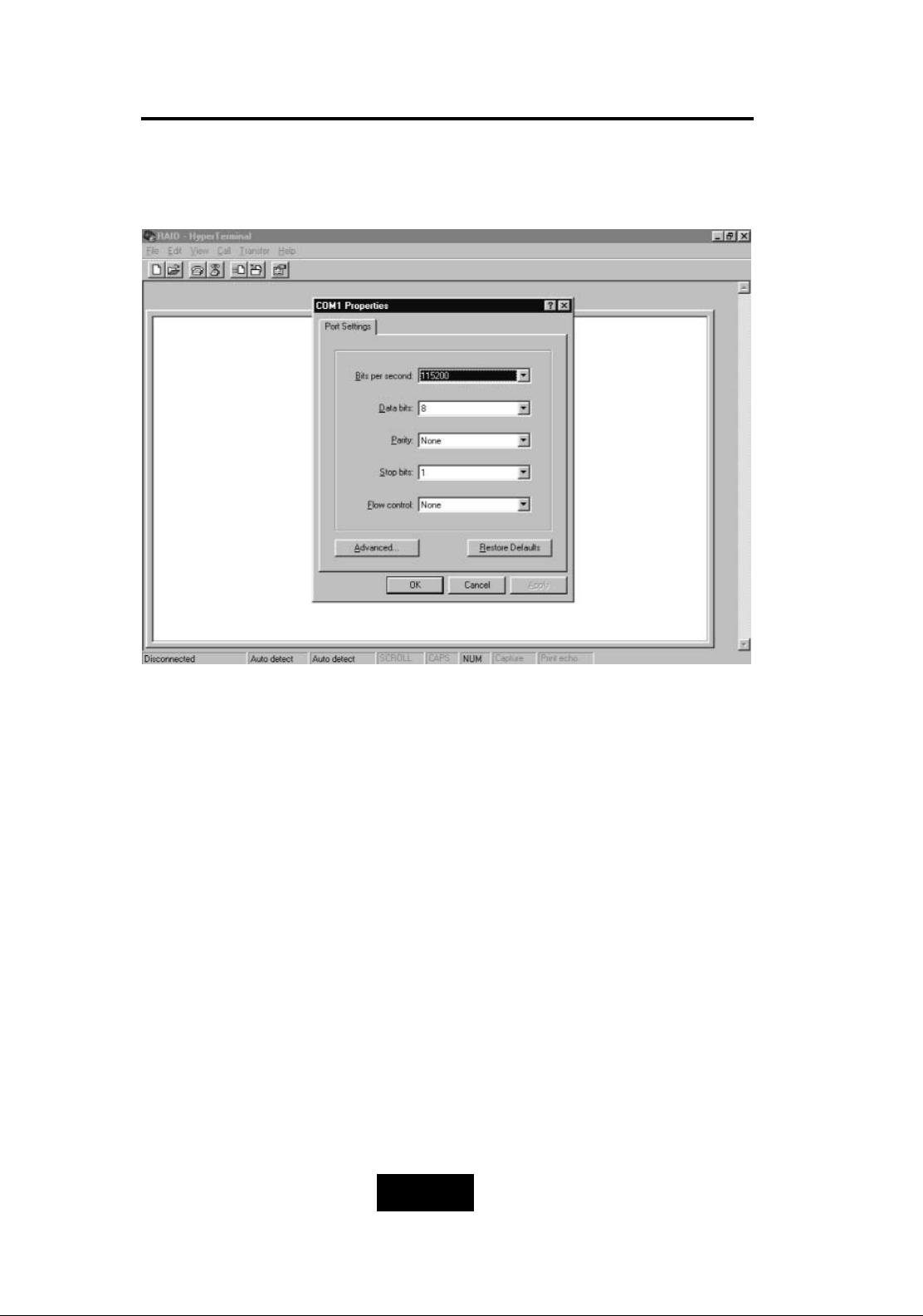
Please configure the VT100 terminal setting to the values shown
below :
VT100 terminal ( or compatible ) set up
Connection Serial Port ( COM1 or COM2 )
Protocol RS232 ( Asynchronous )
Cabling Null-Modem cable
Baud Rate
115,200
Data Bits 8
Stop Bit
1
Parity None
Page 59
4-77
Advanced Information
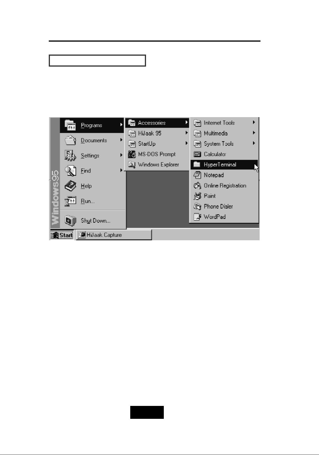
SSeettuupp VVTT110000 TTeerrmmiinnaall
Example : Setup VT100 Terminal in Windows
Step 1.
Page 60
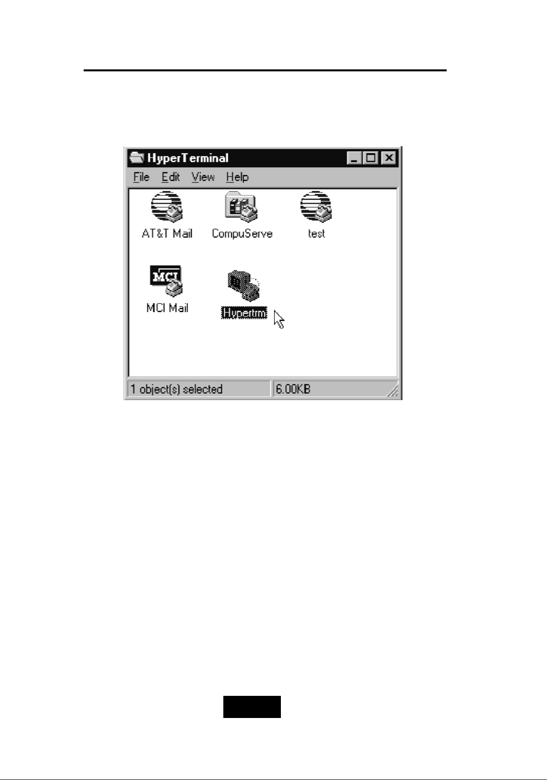
4-88
Advanced Information
Step 2.
Page 61
4-99
Advanced Information
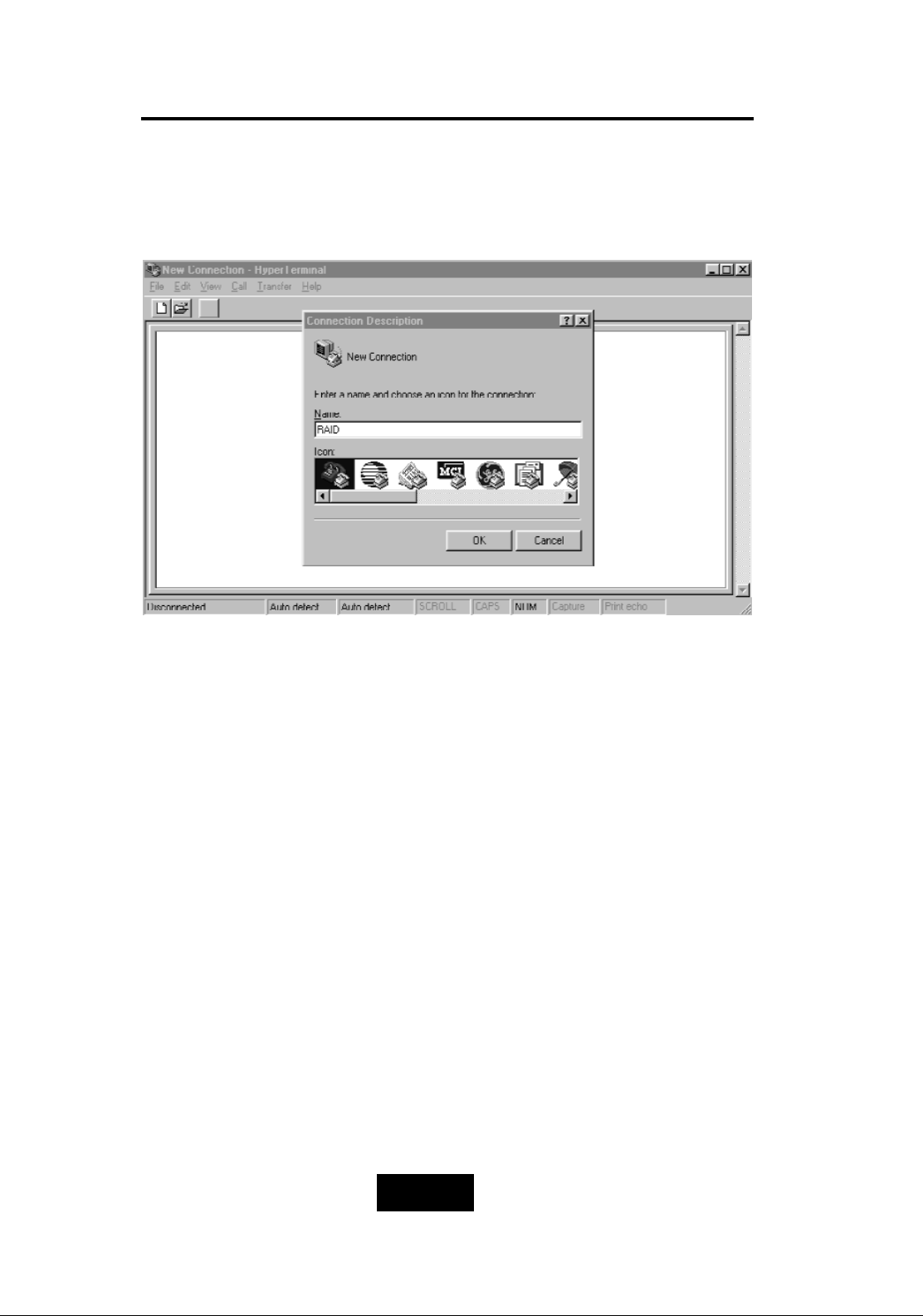
Step 3. Enter a name for your Terminal.
Page 62
4-110
Advanced Information
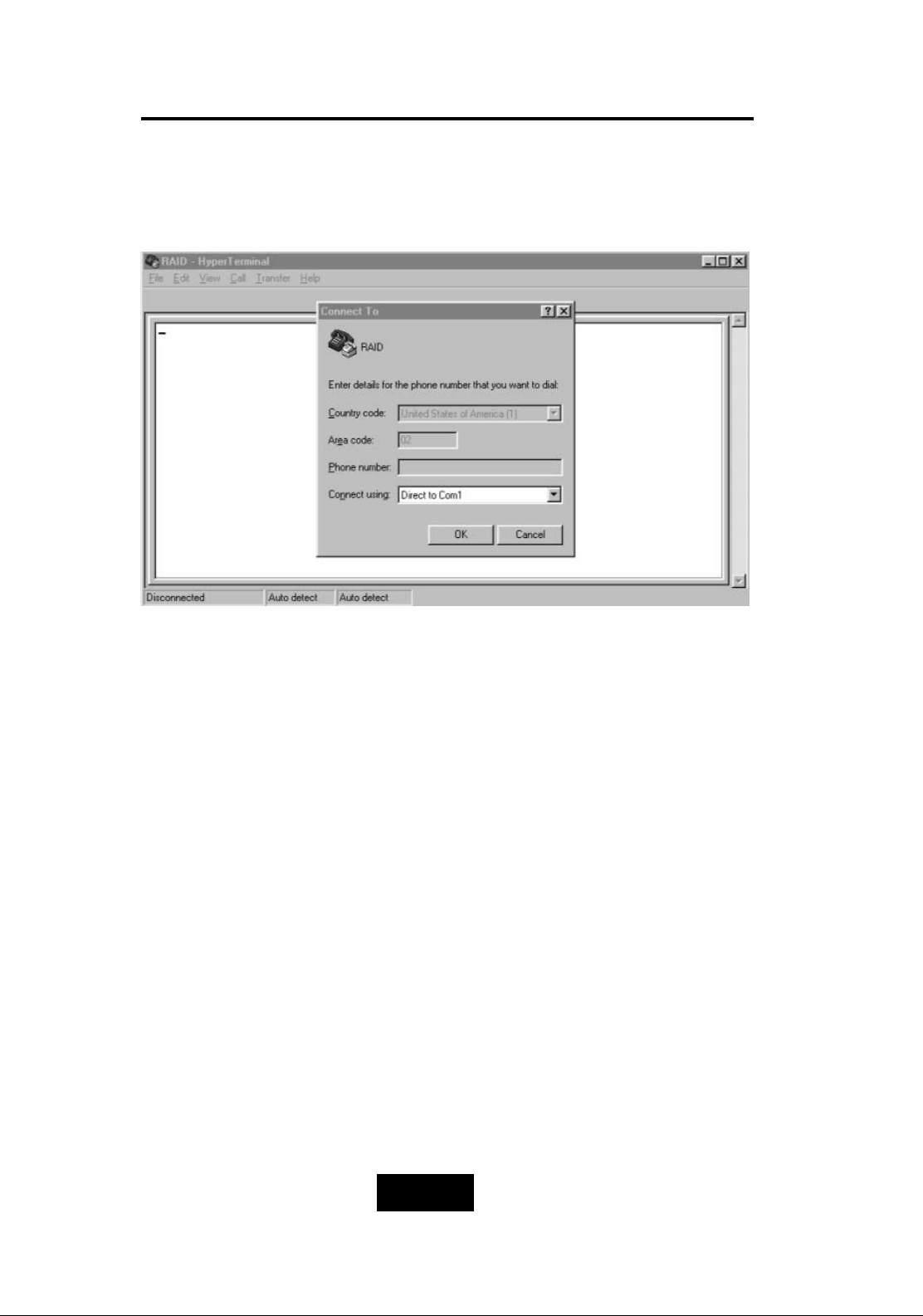
Step 4. Select a connecting port in your Terminal
Page 63
4-111
Advanced Information
Step 5. Port parameter setting
Page 64
4-112
Advanced Information
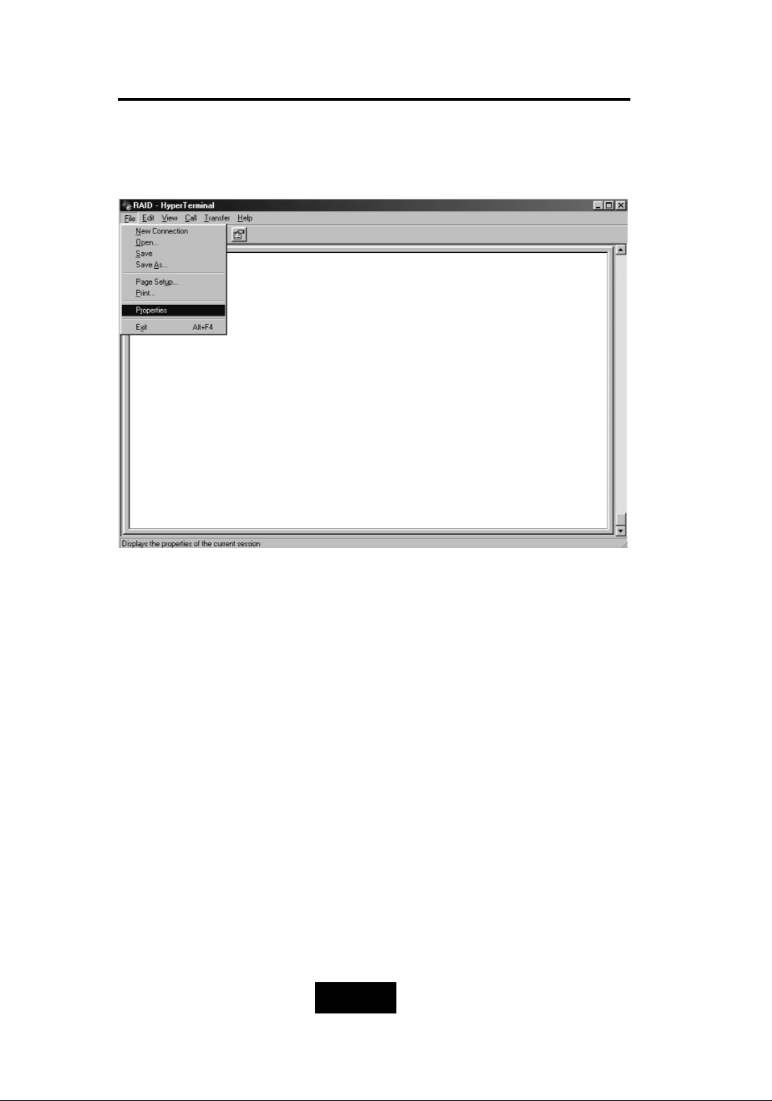
Step 6.
Page 65
4-113
Advanced Information
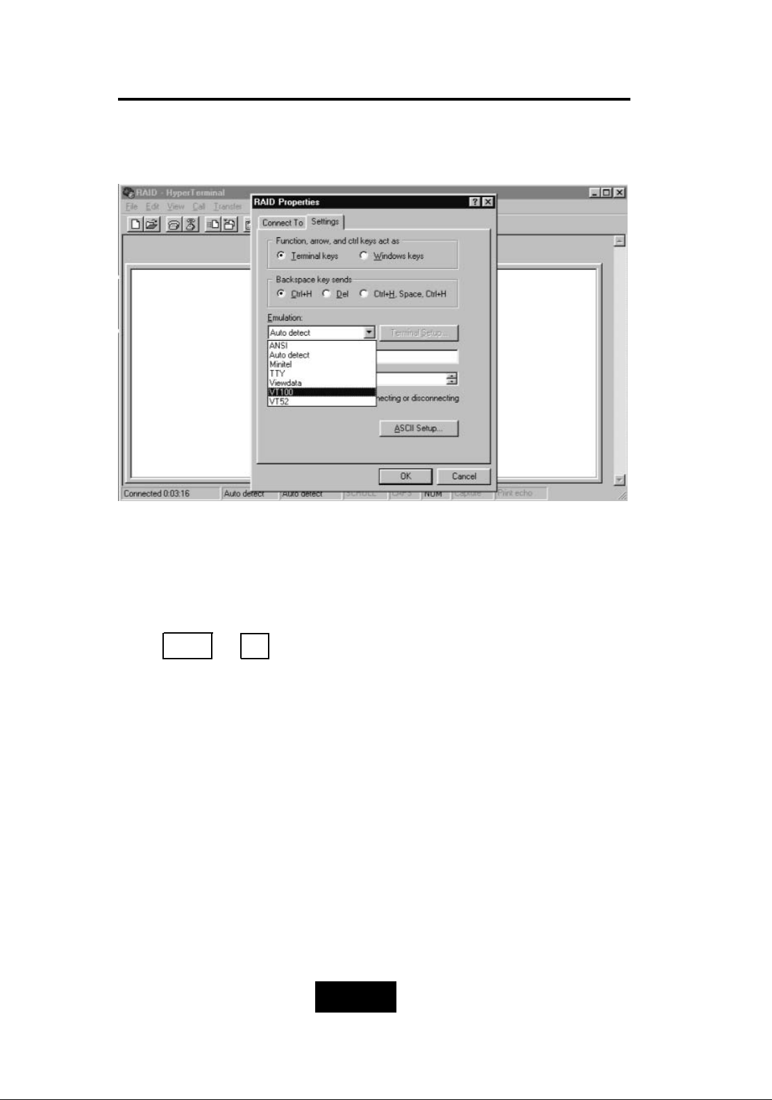
Step 7. Select emulate VT100 Mode
After you finishing the VT100 Terminal setup, you may restart
your Disk Array and press “ Ctrl + D “ keys ( in your Terminal ) to link
the Disk Array and Terminal together.
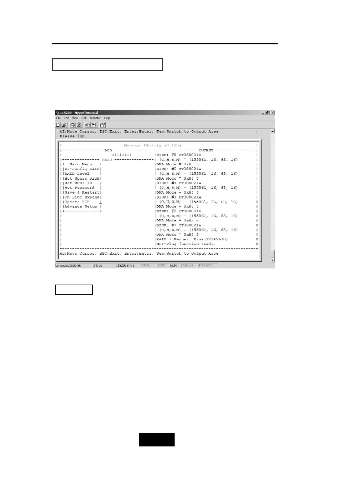
Press Ctrl + D to display the disk array Monitor Utility
screen on your VT100 Terminal.
Page 66
4-114
Advanced Information
SSttaarrtt ttoo UUppddaattee FFiirrmmwwaarree
1. Move the cursor to “ Update ROM “ and press “Enter”.
Unpredictable results will occur if firmware update is attempted
during Host computer and Disk Array activity. All activity to the
controller should be stopped before updating firmware.
Warning !
Page 67
4-115
Advanced Information
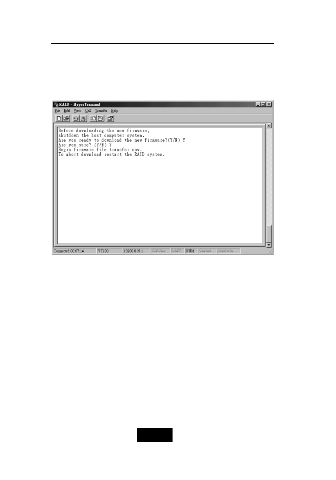
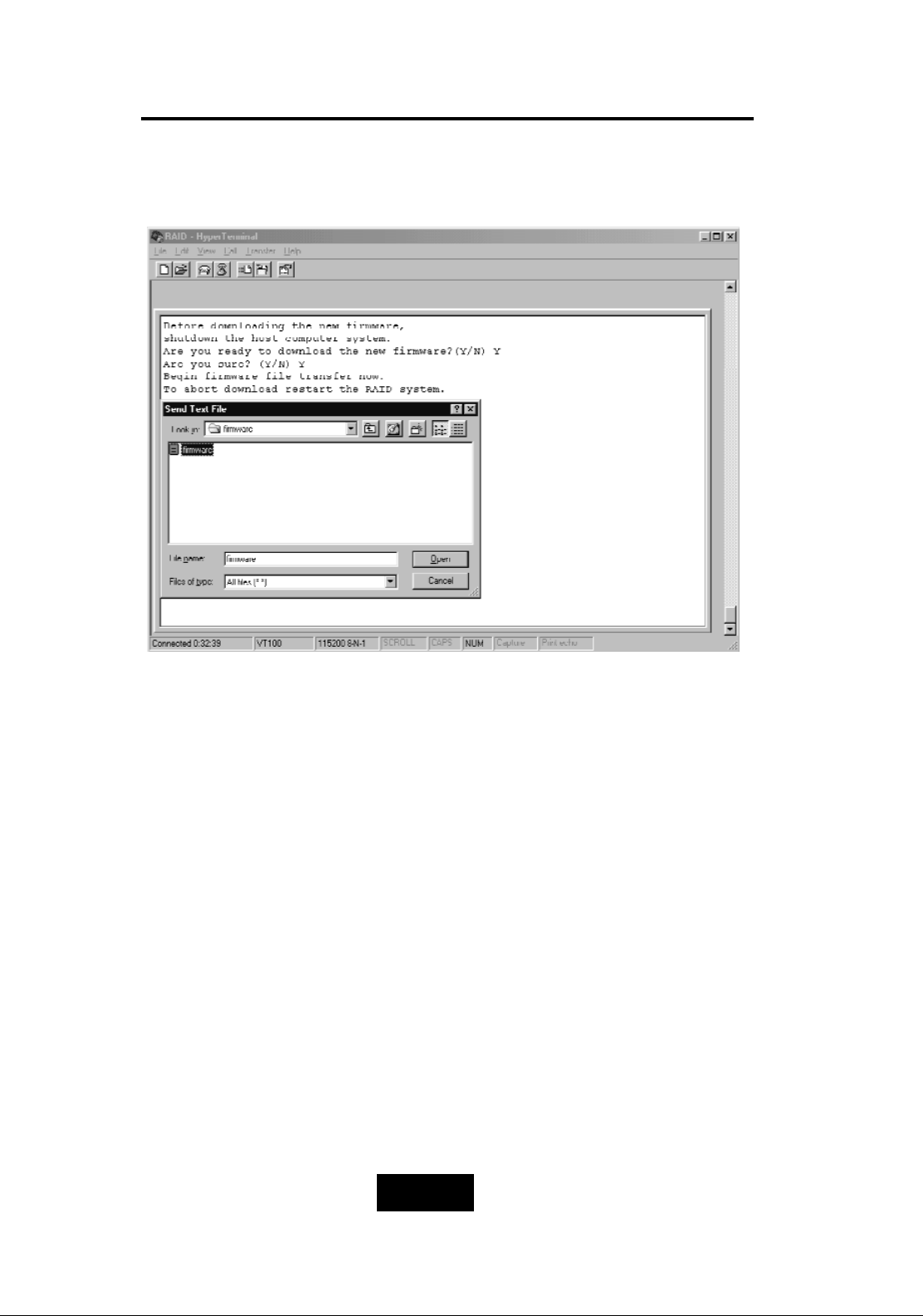
2. Press “ Y“ to download the new firmware and
press “ Y“ again to confirm the Update.
Page 68
4-116
Advanced Information
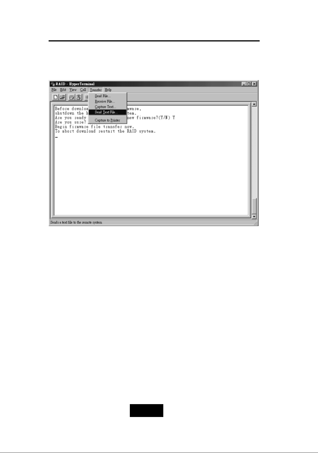
3. Select transfer “
Send Text File
“ and press Enter.
Page 69
4-117
Advanced Information
4. Locate the new Firmware file on your PC.
Page 70
4-118
Advanced Information
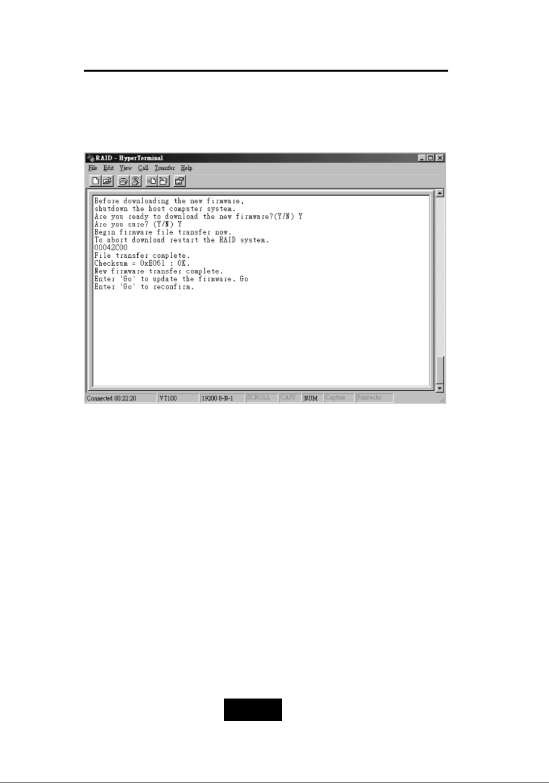
5. Press “
Go
“ to confirm to download the new firmware.
Page 71
4-119
Advanced Information
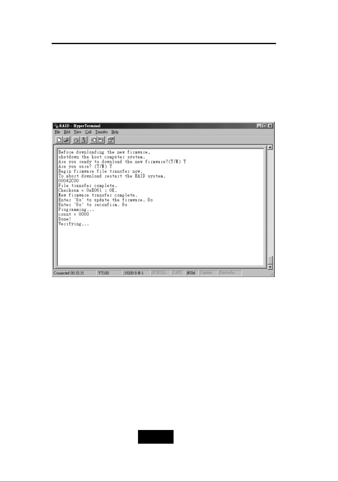
6. Type “
Go
“ to reconfirm and the firmware will begin to be
reprogrammed.
7. After verifying,
the Disk Array
will reset automatically to activate
the new firmware.
Page 72
4-220
Advanced Information
Main screen
RAID Group
RAID 1/2/3/4
Advance Setep
Reconfig RAID
Yes / No
Select
Disk Number
Hot Spare Disk
( Yes / No )
No
RAID Level
(0,1,3,5,0+1,None)
Save Configuration
& Restart
Yes
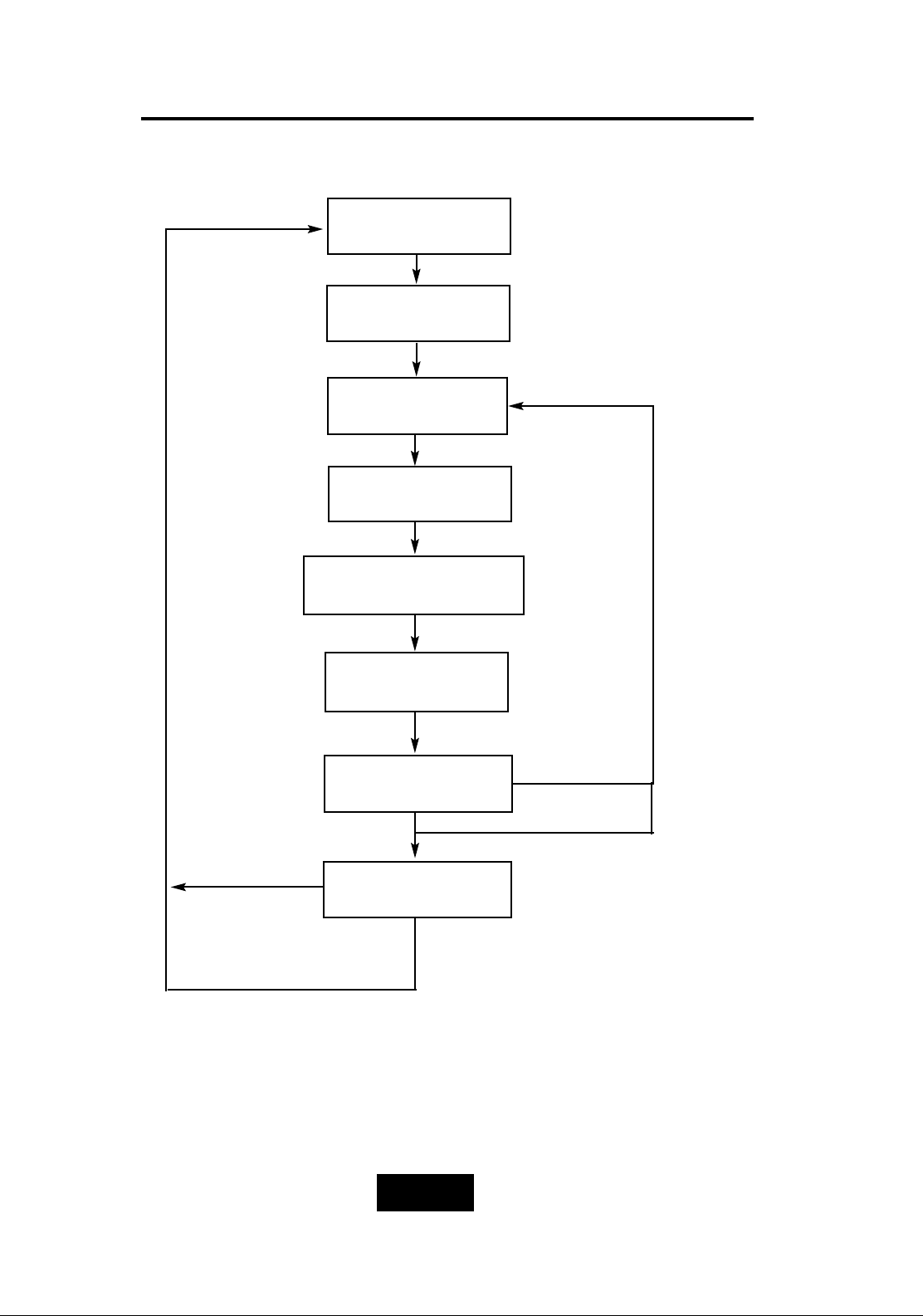
MMuullttiippllee RRAAIIDD CCoonnffiigguurraattiioonn pprroocceedduurreess
(VT100 Terminal)
Setup RAID2/3/4
Page 73
4-221
Advanced Information
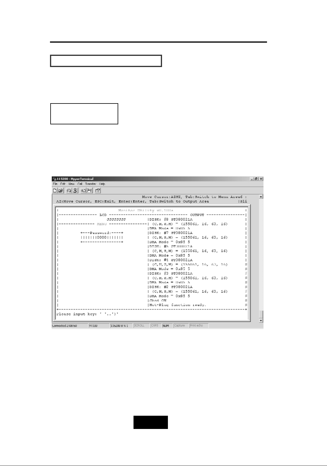
HHooww TToo SSeettuupp MMuullttiippllee RRAAIIDD
The system can Setup as multiple RAID Groups (Max 4 RAID
Groups).
Step 1.
Key-in password to enter the main menu.
(Default “0000”)
RAID Group 1 Setup
Warning:Be sure to backup your data first before attempting to
change RAID setup from single RAID Group to multiple RAID
Groups.
Page 74
4-222
Advanced Information
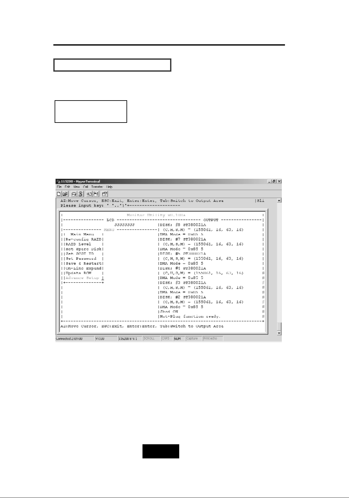
HHooww TToo SSeettuupp MMuullttiippllee RRAAIIDD
Step 2.
Select “Advance Setep”
RAID Group 1 Setup
Page 75
4-223
Advanced Information
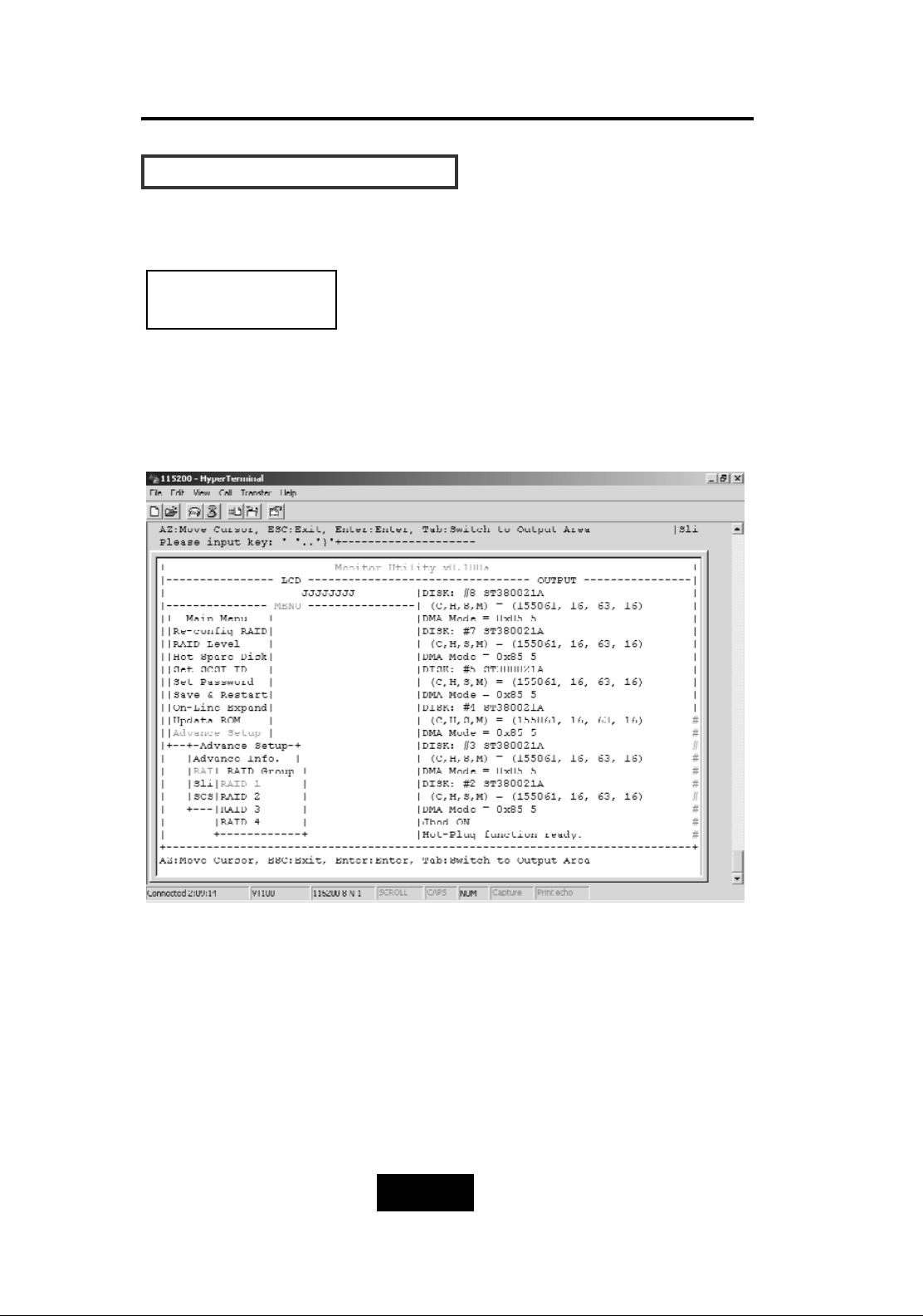
HHooww TToo SSeettuupp MMuullttiippllee RRAAIIDD
Step 3.
Select “RAID 1” in “RAID Group”.
RAID Group 1 Setup
Page 76
4-224
Advanced Information
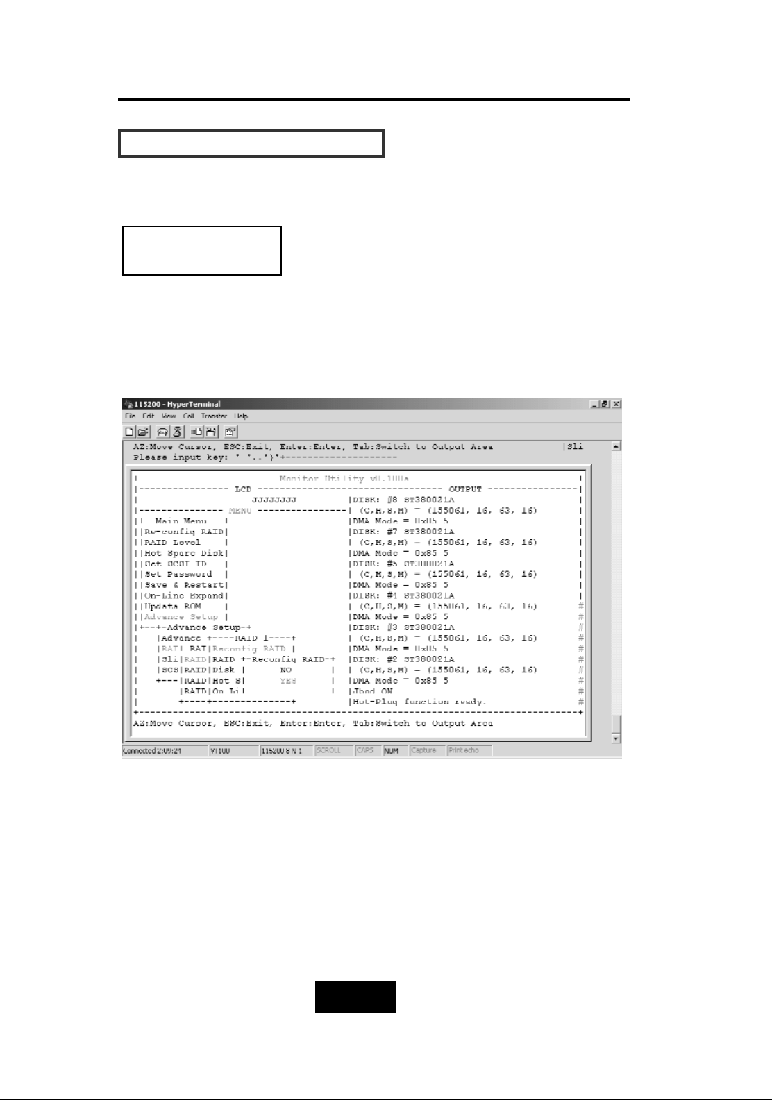
HHooww TToo SSeettuupp MMuullttiippllee RRAAIIDD
Step 4.
Select “Yes” for setting all the configurations.
RAID Group 1 Setup
Page 77
4-225
Advanced Information
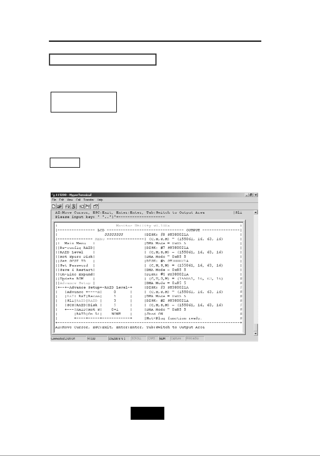
HHooww TToo SSeettuupp MMuullttiippllee RRAAIIDD
Step 5.
Move the cursor to the expected RAID Level ( 0, 1, 3, 5, 0+1,
None ), and press “Enter” to confirm it.
All data will be lost by changing the RAID level.
RAID Group 1 Setup
Warning
Page 78
4-226
Advanced Information
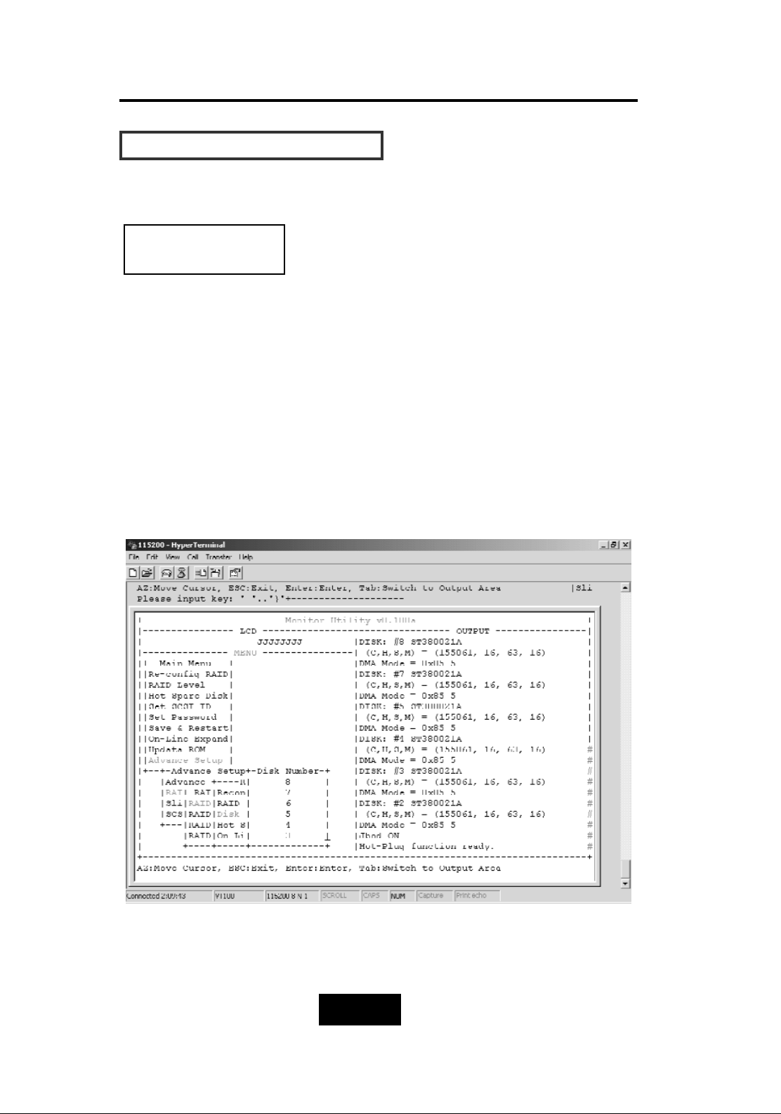
HHooww TToo SSeettuupp MMuullttiippllee RRAAIIDD
Step 6.
Select how many Drives to setup in RAID Group 1.
(Only the HDD numbers installed in the system will be displayed)
Step 7.
In Hot Spare, Select “Yes” to set one Disk Drive as a Hot-spare Disk
(This Valid in RAID Level 5 and 3, the total number of Disk Drive
installed must be more than 3 Disk Drives).
RAID Group 1 Setup
Page 79
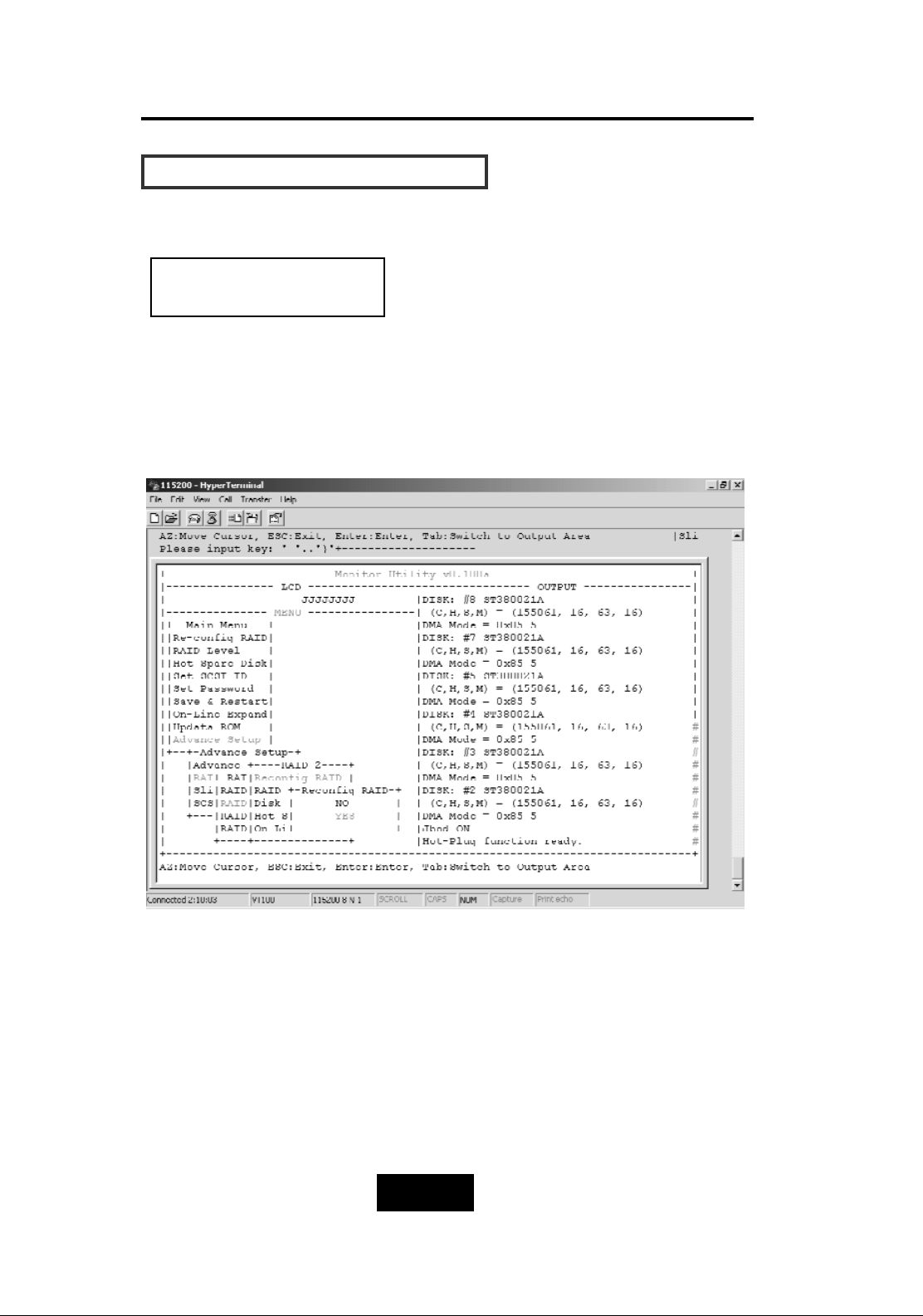
4-227
Advanced Information
HHooww TToo SSeettuupp MMuullttiippllee RRAAIIDD
Follow the step for setting RAID Group 1 to setup the 2-4 RAID
Groups.
RAID Group 2 -4 Setup
Page 80
4-228
Advanced Information
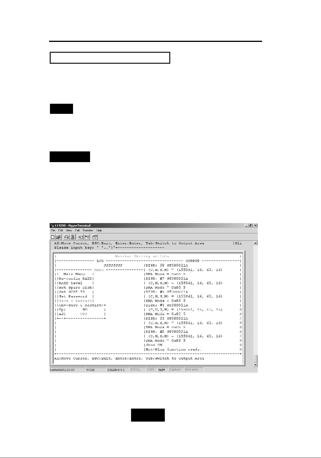
HHooww TToo SSeettuupp MMuullttiippllee RRAAIIDD
Select “Save & Restart” and choose “Yes” to save and activate the
settings.
Warning! All Data will be lost if you changed the RAID
level.
Stop
WARNING
Saving configuration changes causes the disk array controller’s
working parameters to change. This can produce unpredictable
results if it occurs during Host and Array activity. All activity to the
controller should be stopped before saving configuration changes.
Page 81
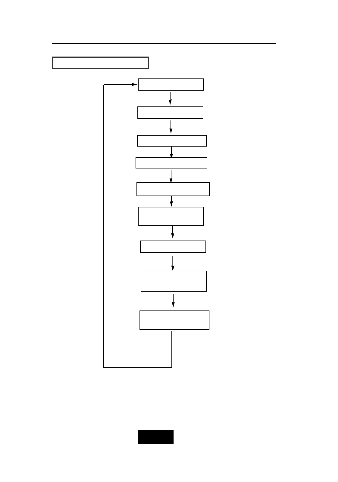
4-229
Advanced Information
SSlliiccee aanndd LLUUNN MMaappppiinngg
Main Screen
Advanced Setup
Set LUN Mapping
LUN 0 ~ LUN 7
RAID 1/ 2/3/4
Slice Number /
Disable
Save Configuration
& Restart
Slice
SCSI Params
Primary/Secondary
Page 82
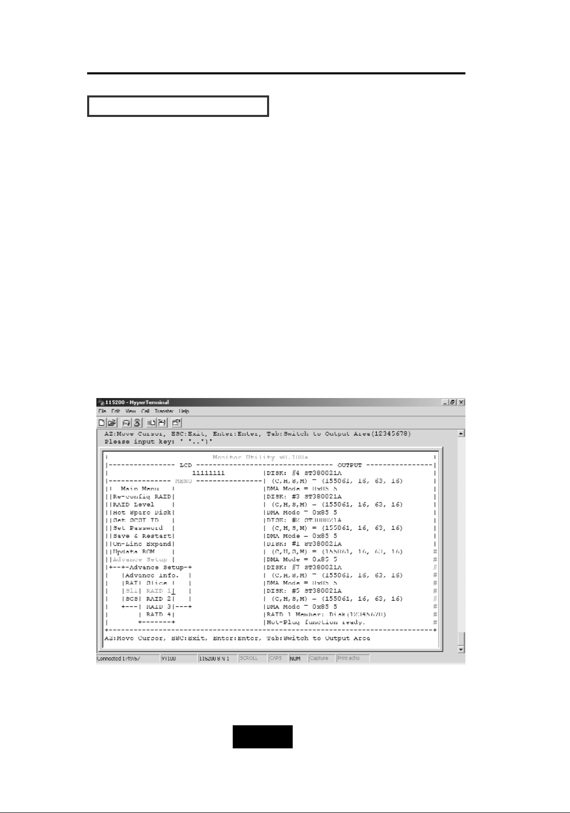
4-330
Advanced Information
SSlliiccee aanndd LLUUNN MMaappppiinngg
Step 1.
Enter Main menu and choose “Advance Setup”.
Step 2.
Select “Slice” to partition the RAID capacity.
Step 3.
Choose RAID Groups which you want to partition the slice capacity.
After completing the RAID Group setup (single or multiple), you
could partition the capacity to “Slice” and map to different “LUN”
Numbers. (The following illustration is for Single RAID Group.)
Page 83
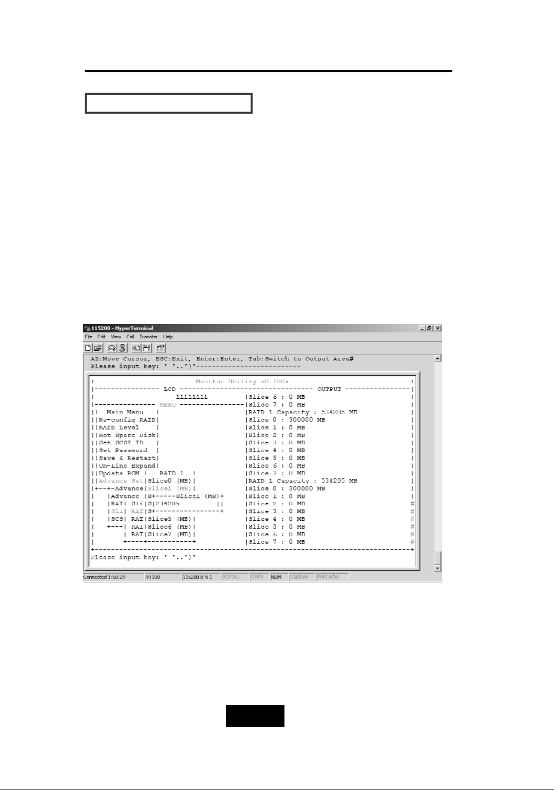
4-331
Advanced Information
SSlliiccee aanndd LLUUNN MMaappppiinngg
Step 4.
Select “Slice 0”, key-in the size in MB for Slice 0.
Step 5.
Select “Slice 1”, key-in the size in MB for Slice 1 (the system will
display the rest capacity automatically).
Page 84
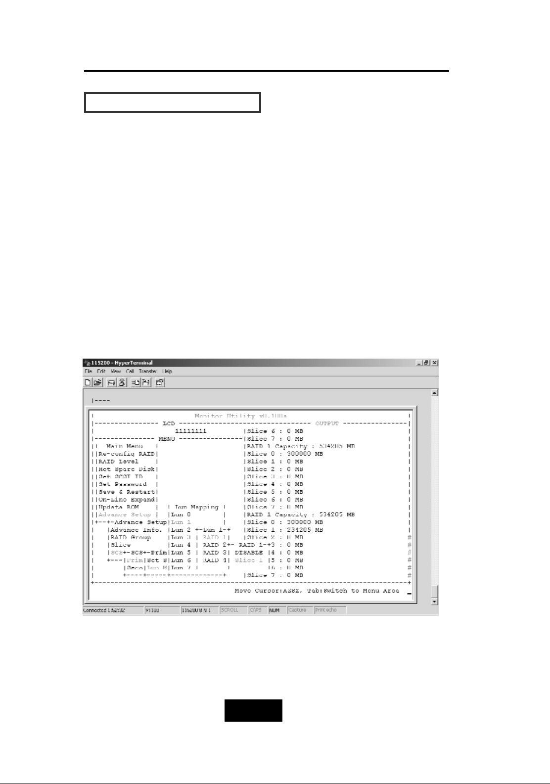
4-332
Advanced Information
SSlliiccee aanndd LLUUNN MMaappppiinngg
Step 6.
Select “SCSI Params” to choose the “Primary SCSI” or “Secondary”
(in case you have dual-host), then setup SCSI ID for each SCSI Host.
Step 7.
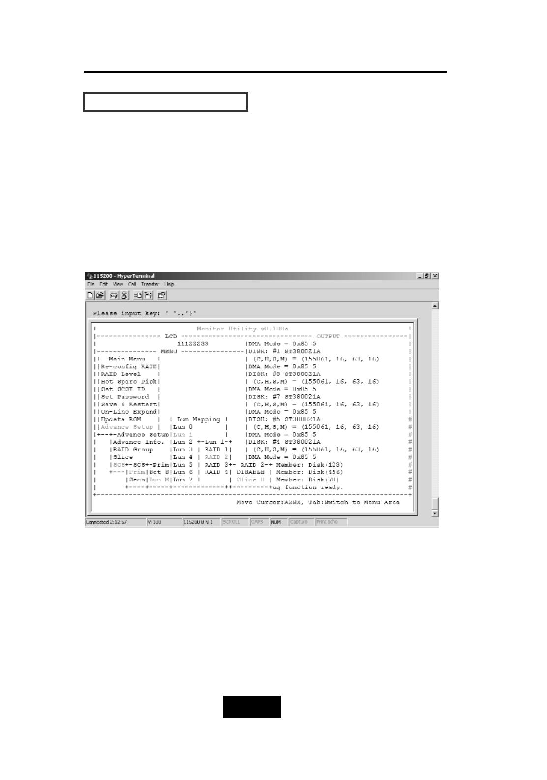
Choose “LUN mapping”. Map the expected LUN No. to expected
RAID Group’s Slice No.
Example: 1 (Single Host, Single RAID)
“LUN 0” mapping to “RAID 1”, “Slice 0”.
“LUN 1” mapping to “RAID 1” , “Slice 1”
Page 85
4-333
Getting Started
SSlliiccee aanndd LLUUNN MMaappppiinngg
Example 2: (Single Host Multiple RAID)
“LUN 0” maps to “RAID1” of “Slice 0”
“LUN 1” maps to “RAID2” of “Slice 0”
Example 3: (Cluster in Single RAID)
Select “Primary SCSI” and maps “LUN 1” to “RAID1” of “Slice 0”
Select “Secondary SCSI” and maps “LUN 0” to “RAID1” of “Slice 0”
Page 86
4-334
Advanced Information
SSlliiccee aanndd LLUUNN MMaappppiinngg
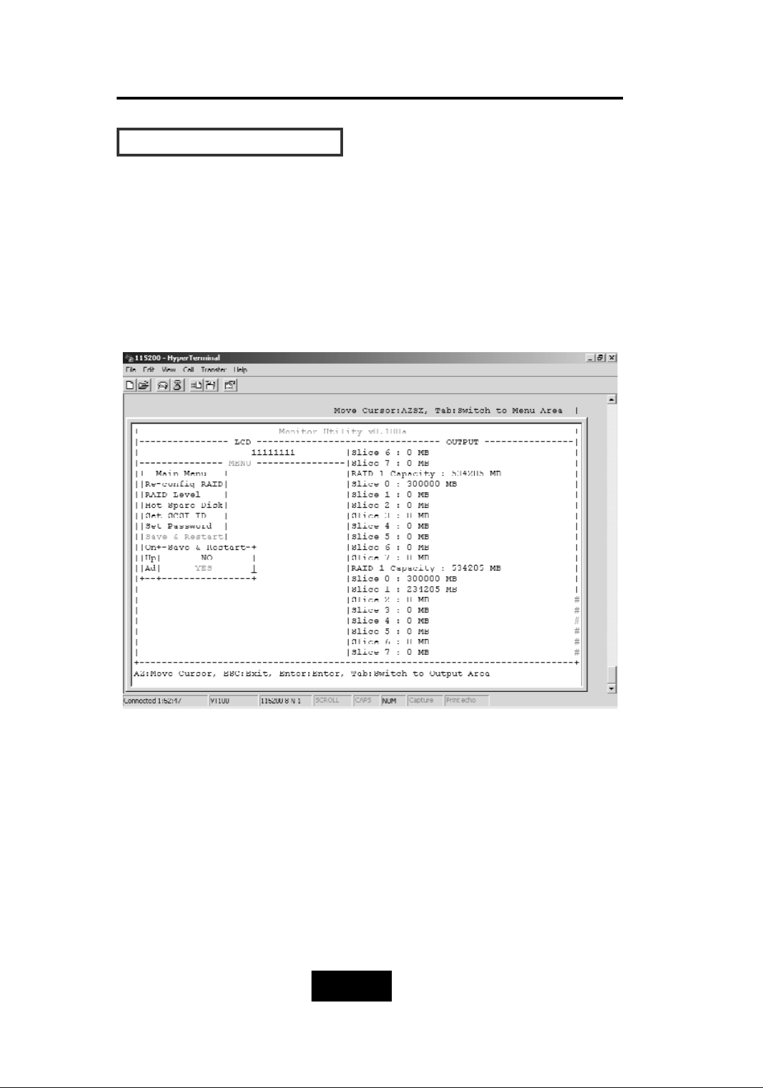
Step 8.
Select “Save & Restart” item and choose “Yes” to save and
activate the settings.
Page 87
4-335
Advanced Information
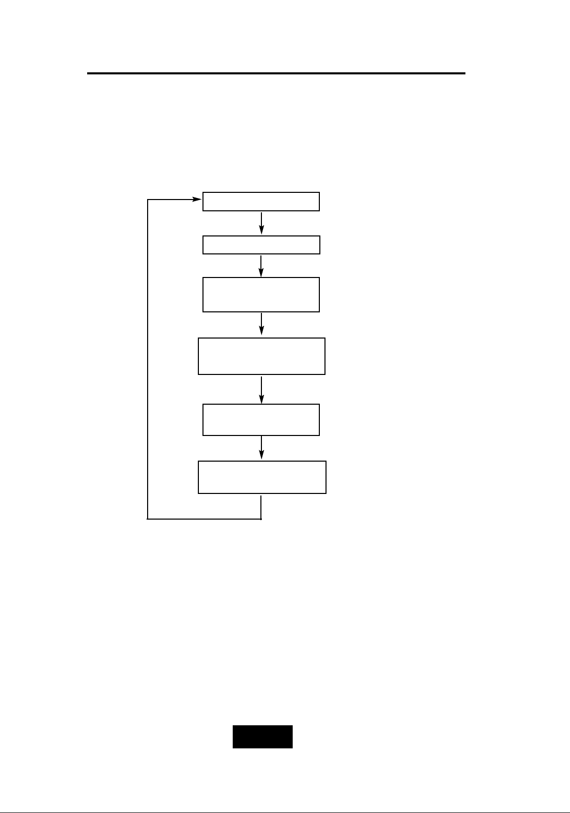
On-Line Expand
(Disk Number/Enable)
Disk Number
( 0 ~ 15 )
On-Line Expand
(Disk Number/Enable)
Advance Setup
RAID GROUP
(RAID1/RAID2)
Main Screen
(Disk Number)
(Enable)
OOnn-LLiinnee EExxppaanndd ffoorr MMuullttiippllee RRAAIIDD GGrroouuppss
(VT100 Terminal)
Page 88
4-336
Advanced Information
OOnn-LLiinnee EExxppaanndd ffoorr MMuullttiippllee RRAAIIDD GGrroouuppss
The RAID capacity can be expanded by adding one or more Disk
Drives into the existing RAID group with properly setup procedures
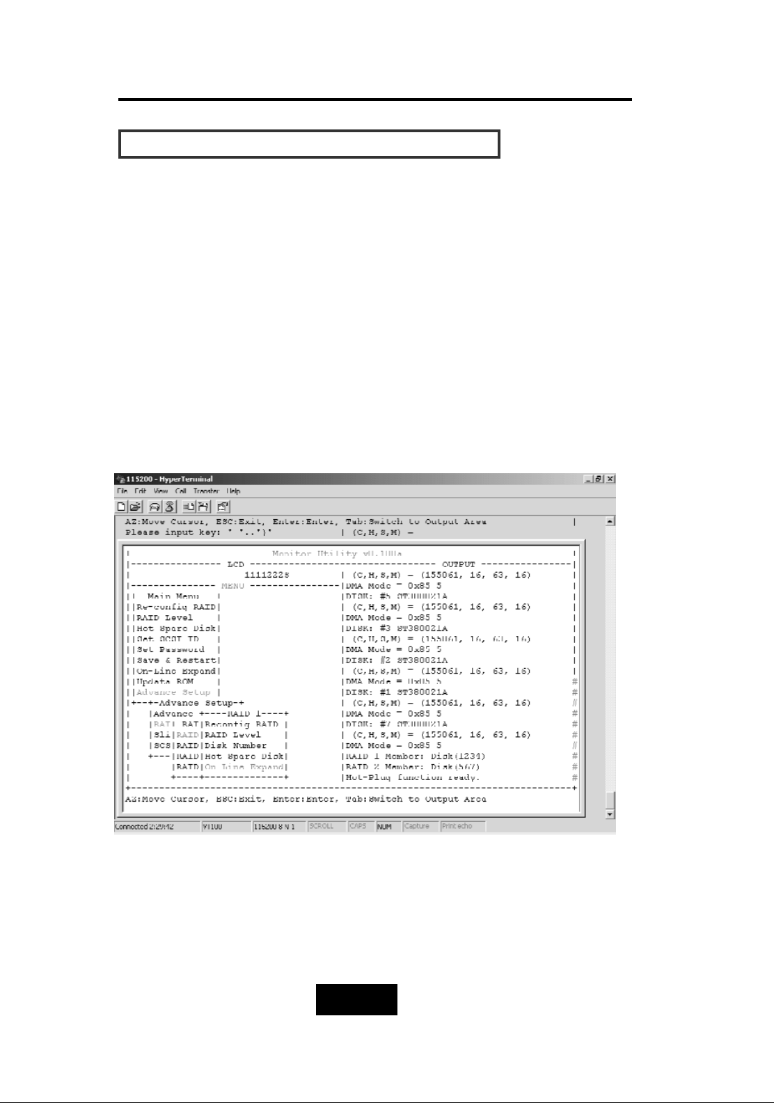
Please add new HDD into the RAID system before you start on-line
expansion.
Step 1.
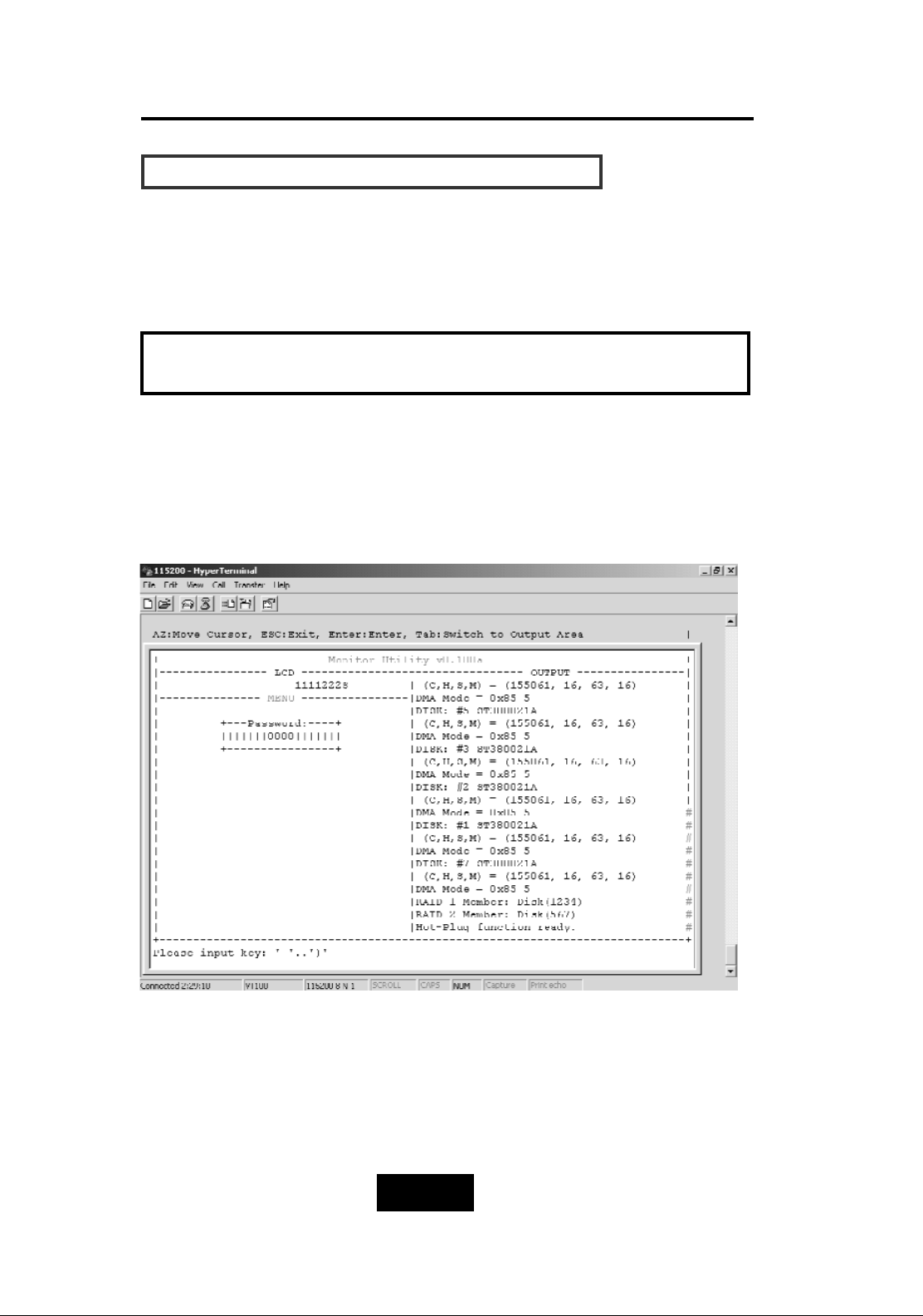
Key-in password to enter the main menu. (Default “0000”)
Page 89
4-337
Advanced Information
OOnn-LLiinnee EExxppaanndd ffoorr MMuullttiippllee RRAAIIDD GGrroouuppss
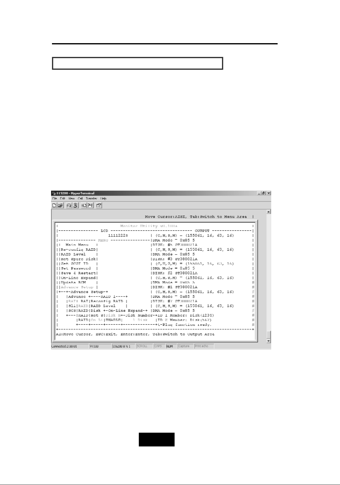
Step 2.
Select “RAID Group”.
Step 3.
Choose “RAID 1-4” to expand the capacity to expected RAID
Groups.
Step 4.
Select “On-Line Expand”.
Page 90
4-338
Advanced Information
OOnn-LLiinnee EExxppaanndd ffoorr MMuullttiippllee RRAAIIDD GGrroouuppss
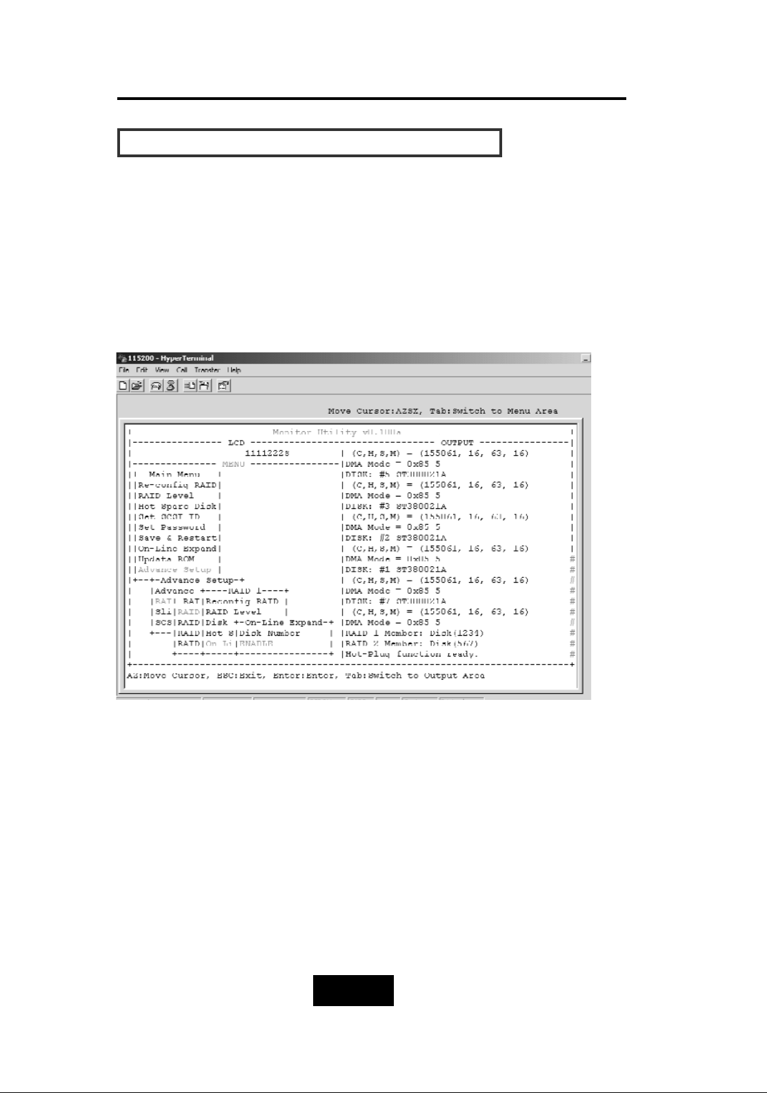
Step 5.
Select “Disk Number” then choose how many disks to add to the
RAID Group (only the number of disks installed will be displayed).
The rest of disks not adding to the RAID groups will be treated as
spare disks.
Page 91
4-339
Advanced Information
OOnn-LLiinnee EExxppaanndd ffoorr MMuullttiippllee RRAAIIDD GGrroouuppss
Step 6.
Select “On-Line Expand” then “Enable” to save and activate the
settings.
Page 92
5-11
Hot Swap
Chapter 5: “Hot Swap”
This chapter explains how to remove and install the “Hot-Swap”
parts without interrupting the data access while the disk array is on.
The “Hot-Swap” parts include :
Hard Disk Drives
Redundant Power Supply Units
Cooling Fans
Follow the steps below and refer to the diagrams to remove and
install the “Hot-Swap” parts.
Page 93
5-22
Hot Swap
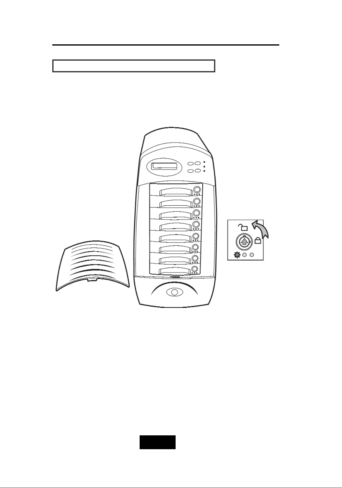
RReemmoovviinngg // IInnssttaalllliinngg HHaarrdd DDiisskk ddrriivveess
a.Unlock the HDD tray
(When a HDD error occurs, the HDD LED indicator lights up “RED”)
Figure: Swap HDD(Unlock)
Page 94
5-33
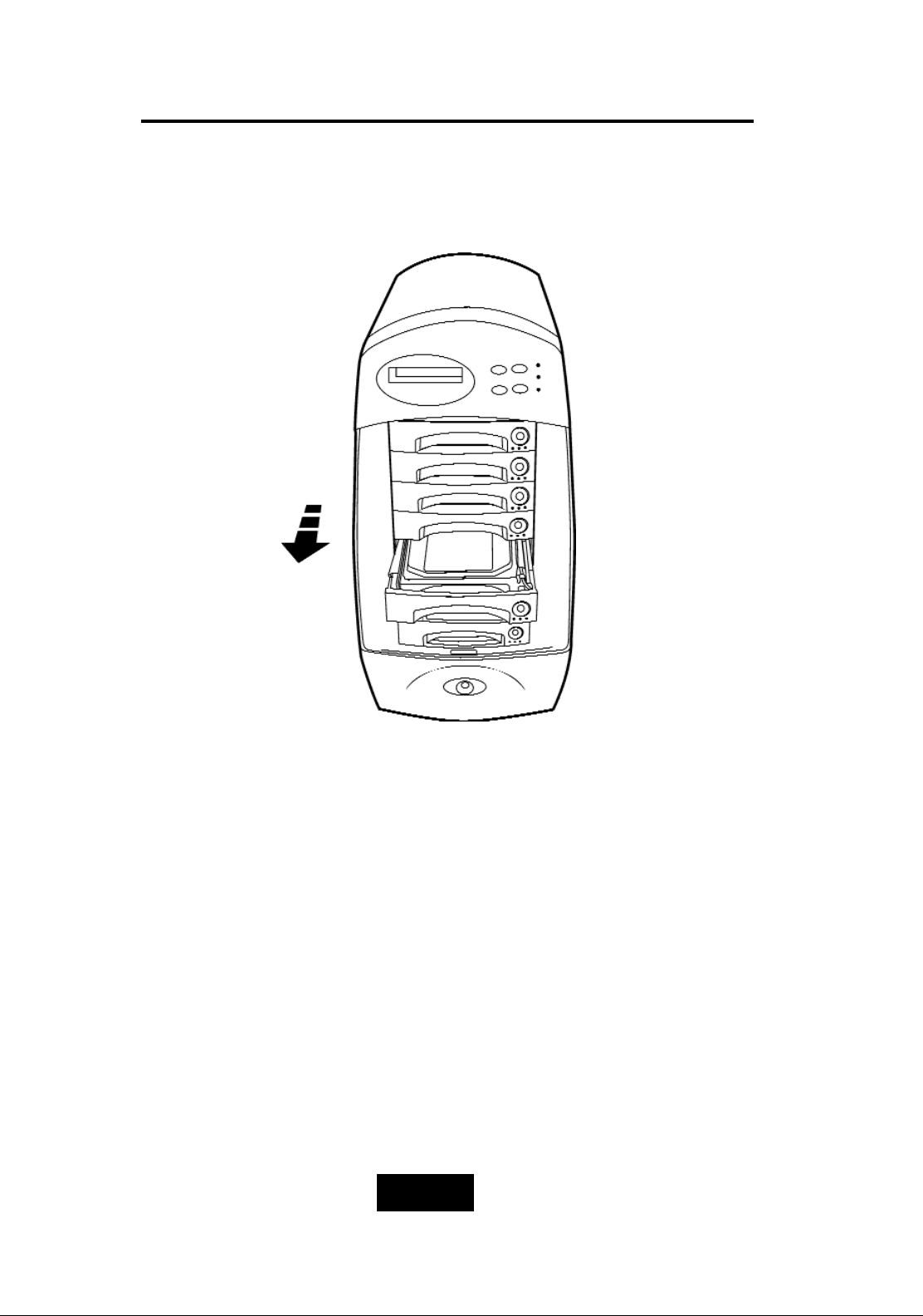
Hot Swap
b.Gently pull-oout the HDD tray
Figure : Swap HDD (Pull-out)
Page 95
5-44
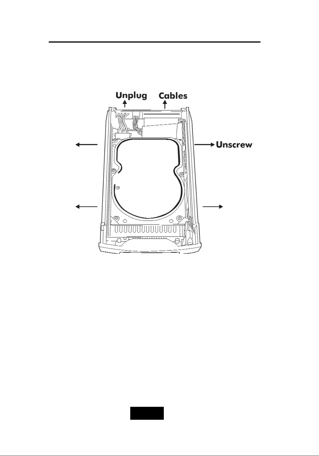
Hot Swap
c.Unscrew and unplug the cables
Figure: Swap HDD(Unplug cables)
Page 96
5-55
Hot Swap
d.Replace with a new Hard Disk Drive
It must be same capacity or greater than the faulty drive, if you
replace with a Hard disk Drive of insufficient capacity, the Disk
Array’s built-in buzzer will sound and the intelligent Auto-Rebuild
function will not be started.
* For best performance, we recommend you swap with an
identical Hard Disk Drive.
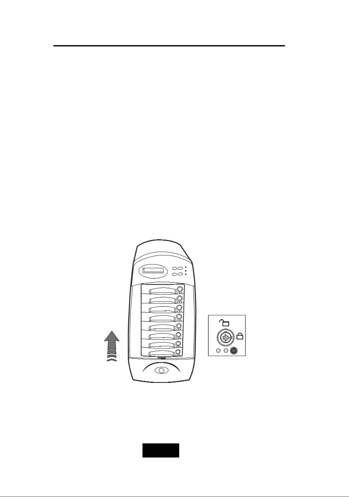
e.Gently Slide-iin the HDD tray and lock up to start the AutoRebuild
While you have installed the replacement disk drive, screw in
all the screws and plug in the cables, you may now gently slide
in the HDD tray into the chassis and lock up it.
* Data Auto-Rebuild will be started automatically when you lock
up the HDD tray.
Figure: Swap HDD(Lock Up)
Page 97
5-66
Hot Swap
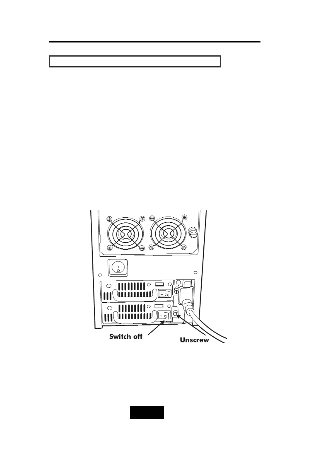
RReemmoovviinngg // IInnssttaalllliinngg tthhee RReedduunnddaanntt PP//SS UUnniitt
There are two LED indicators on the front panel which display the
status of the redundant power supplies. While the power supply
is working properly the two LED indicators light up “ Green “, if any
one of them fail, the LED indicator will go off and the redundant
power supply buzzer alarm will sound.
When you need to replace the redundant power supply unit ,
refer to the redundant power supply status LED indicator on the
front panel to find the failed power supply unit and follow these
steps to swap it.
a. Unscrew the faulty unit
(For Safety reasons, you should switch off the faulty unit’s
power switch)
Figure: Swap P/S unit ( Unscrew )
Page 98
5-77
Hot Swap
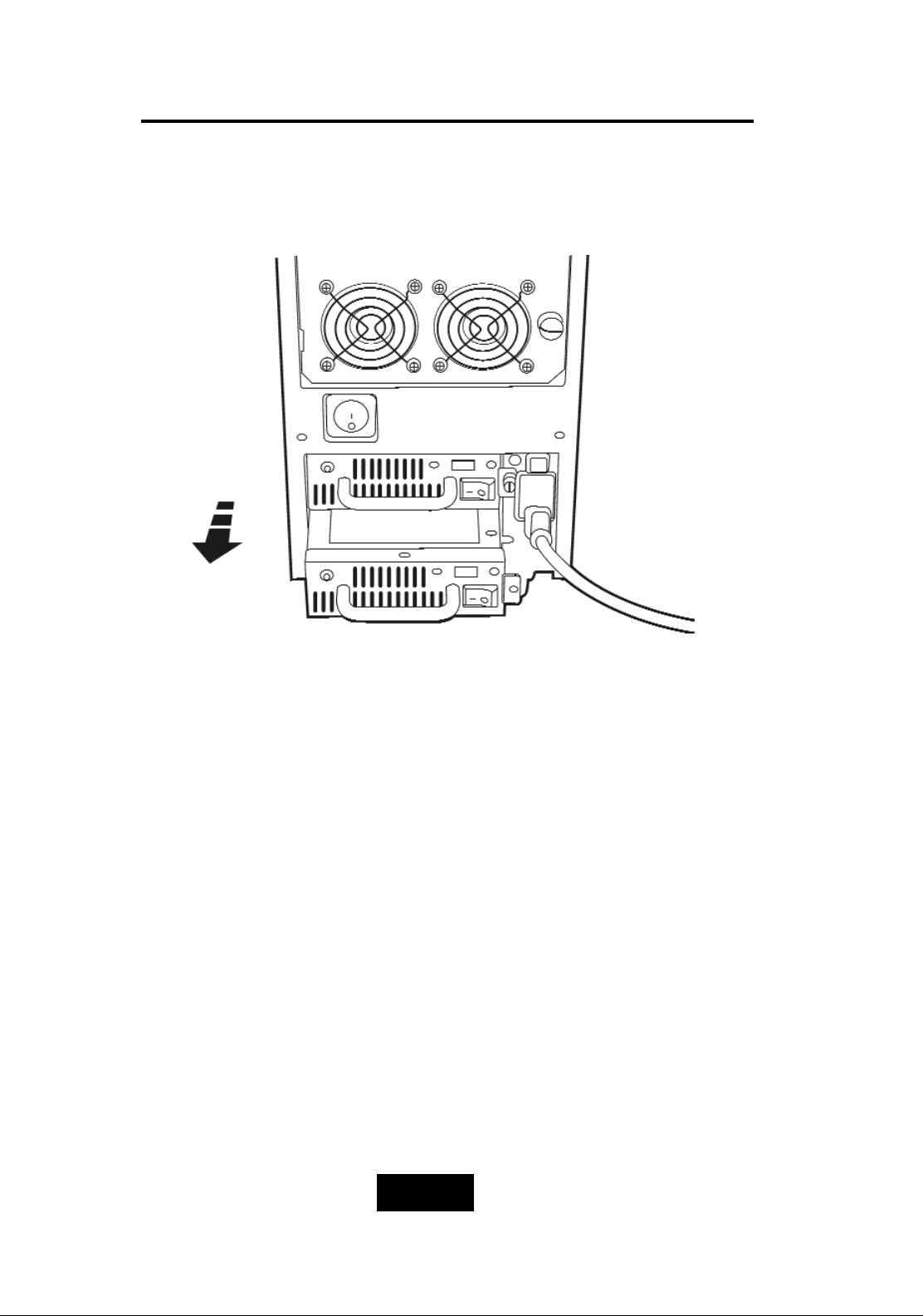
b.Replace with a new power supply unit
Figure: Swap P/S unit ( Swap with a new unit )
Page 99
5-88
Hot Swap
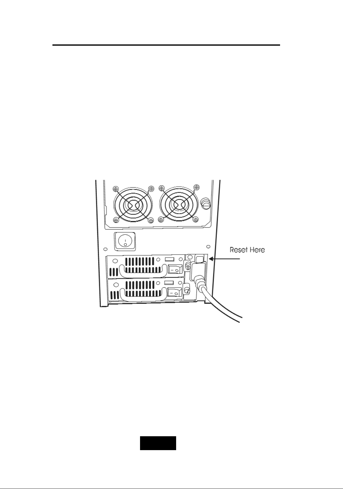
c. Press the Power Supply Reset switch
When you replace a new power supply unit, you should then
push the power supply reset switch on the power supply frame
to stop the buzzer alarm and link the two power supply units
together.
The new power supply unit will link with the other unit
immediately and will start working after you press the power
supply reset switch, and the buzzer warning noise will stop.
Reset from the Power supply
Page 100
5-99
Hot Swap
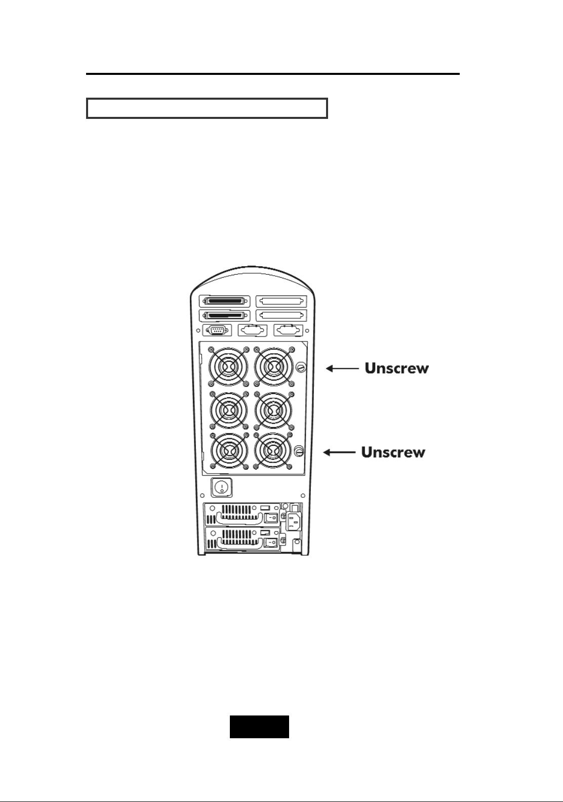
RReemmoovviinngg // IInnssttaalllliinngg CCoooolliinngg FFaannss
Unscrew the Fan door and open the door to a 90 degree
position
! Caution
: Be careful , the high speed rotating fans may harm
you. Don’t touch the rotating Fans, If necessary,
Unplug the Fan power connector first.
Figure: Swap cooling Fan ( Unscrew the Fan Door )
 Loading...