

easyRAID ERP12S-8FR2, ERP12R-6SR2, ERP12S-6SR2, ERP16R-8FR2, ERP16S-8FR2 Quick Installation Manual
...Page 1

easyRAID P12R/S & P16R/S
Quick Installation Guide
42-30000-5197
Fibre to SAS
iSCSI to SAS
SAS to SAS
JBOD
Disk Array Systems
Version 1.1
Page 2

Page 3

Fibre to SAS
iSCSI to SAS
SAS to SAS
JBOD
Disk Array Systems
Model:
ERP12R-8FR2, ERP12S-8FR2, ERP12R-10GR2, ERP12S-10GR2,
ERP12R-6SR2, ERP12S-6SR2, ERP16R-8FR2, ERP16S-8FR2,
ERP16R-10GR2, ERP16S-10GR2, ERP16R-6SR2, ERP16S-6SR2,
ERP16JS-6SR3, ERP16JR-6SR3
Quick Installation Guide
Page 4

Page 5
i
Table of Contents
Preface................................................................................................................... i
WHAT’S IN THE BOX
RAID System Components
Front View ............................................................................................................. 3
Open Front Panel .................................................................................................. 3
Rear View .............................................................................................................4
Controller Interface ...............................................................................................5
Mounting The RAID System
Installing the Slide Rail .......................................................................................... 6
Installing the Rail Extender ................................................................................... 7
Installing Hard Disk
Installing The SAS Disk .........................................................................................8
Installing The SATA Disk .......................................................................................8
Configure RAID System By GUI
Set Up The LAN Connection.................................................................................. 9
Quick Setup By GUI ............................................................................................... 9
Understanding LCD Front Panel
LCD Panel............................................................................................................ 10
LED Defintion ....................................................................................................... 10
Button Function .................................................................................................... 10
Page 6

Page 7
Preface
i
Copyright
Copyright © 2010. All rights reserved. No part of this publication may be reproduced or transmitted in any form
without prior written permission.
Important Safety Instructions, Care and Handling
Before starting with the RAID installation, read this user manual carefully and save it for later reference.
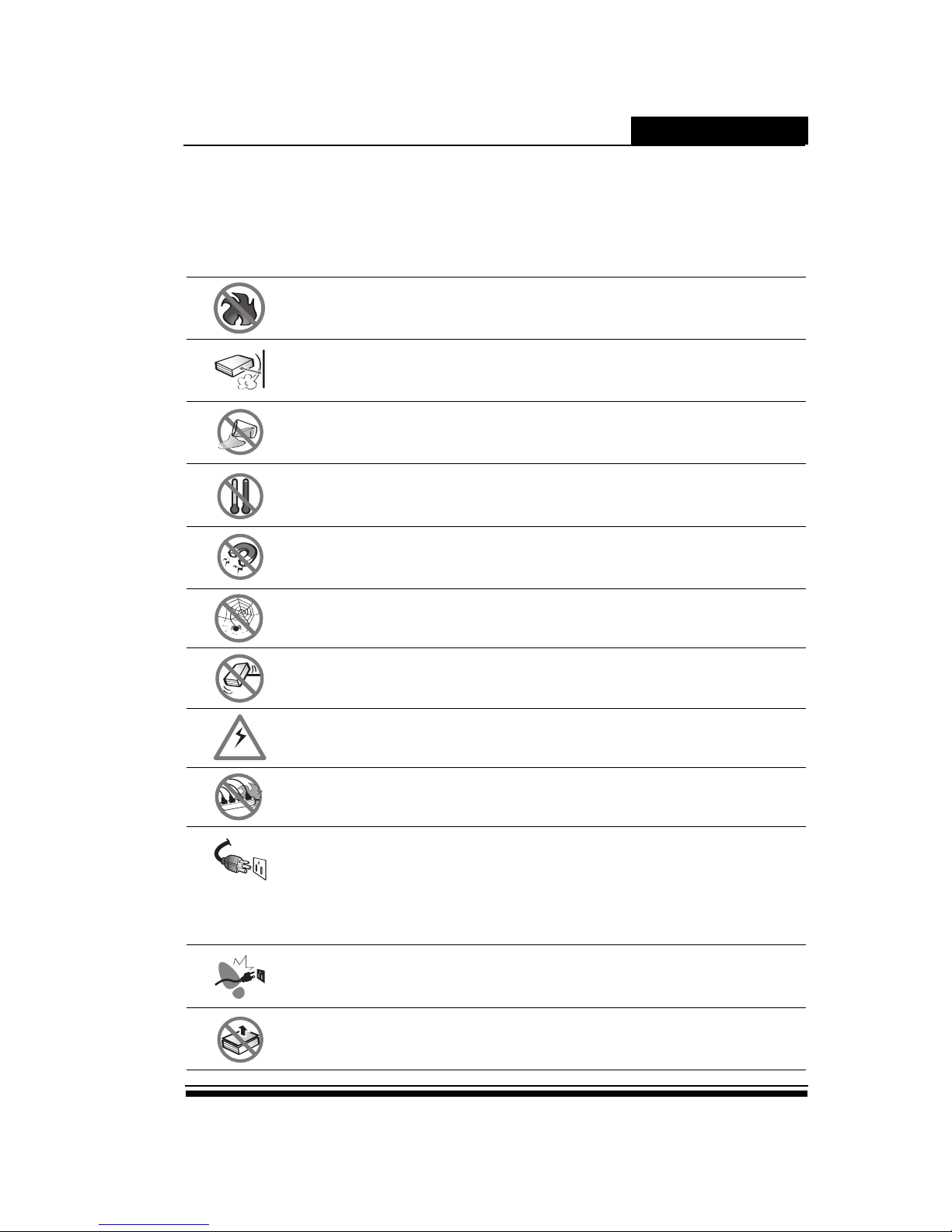
Do not place the RAID system near a radiator or other heat source.
Slots and opening are for ventilation. Never block or cover them.
Do not place the RAID system near water or any liquid.
Protect the RAID system from extremely high or low temperatures.
Keep the RAID system away from magnetic objects.
Keep the RAID system away from dust, sand, or dirt.
Place the RAID system on a stable area. Protect the RAID system from being dropped or
mishandled.
Ensure that the RAID system voltage corresponds to the supply voltage.
If an extension cord or power center is used with the RAID system, make sure that the total current
consumption plugged into the wall outlet does not exceed the ampere rating.
• This power cord will only fit into a grounded type of power outlet.
• Unplug the power cord from the wall outlet before cleaning or servicing.
• Unplug the power cord from the wall outlet and refer to qualified service personnel under the
following conditions:
- If the RAID system has been exposed to water or any liquid.
- If the RAID system has been dropped or the casing damaged.
Do not place the RAID system where the power cord may be stepped on.
•Do not remove the cover.
•Do not attempt to service the RAID system yourself. Opening or removing the cover may expose
you to dangerous voltage or other risks.
L
H
v
Page 8

Preface
ii
To mount the RAID system in standard-sized rack, follow these instructions:
1. Place the RAID system on a hard flat surface with the front panel facing you.
2. Attach a rack–mount bracket to one side of the RAID system with the supplied screws.
Then attach the other bracket to the other side.
3. Make sure the brackets are properly attached to the RAID system.
4. Use the appropriate screws (not included) to securely attach the brackets to your rack.
5. Elevated Operating Ambient - If installed in a closed or multi-unit rack assembly, the operating ambient
temperature of the rack environment may be greater than room ambient. Therefore, consideration should be
given to installing the equipment in an environment compatible with the maximum ambient temperature
specified by the manufacturer.
6. Reduced Air Flow - Installation of the equipment in a rack should be such that the amount of air flow required
for safe operation of the equipment is not compromised.
7. Mechanical Loading - Mounting of the equipment in the rack should be such that a hazardous condition is not
achieved due to uneven mechanical loading.
8. Circuit Overloading - Consideration should be given to the connection of the equipment to the supply circuit
and the effect that overloading of the circuits might have on over current protection and supply wiring.
Appropriate consideration of equipment nameplate ratings should be used when addressing this concern.
9. Reliable Earthing - Reliable earthing of rack-mounted equipment should be maintained. Particular attention
should be given to supply connections other than direct connections to the branch circuit (e.g. use of power
strips).
Page 9
ERP12R/S & ERP16R/S
1
RAID System Task List
RAID System Task List RAID System Task List
RAID System Task List
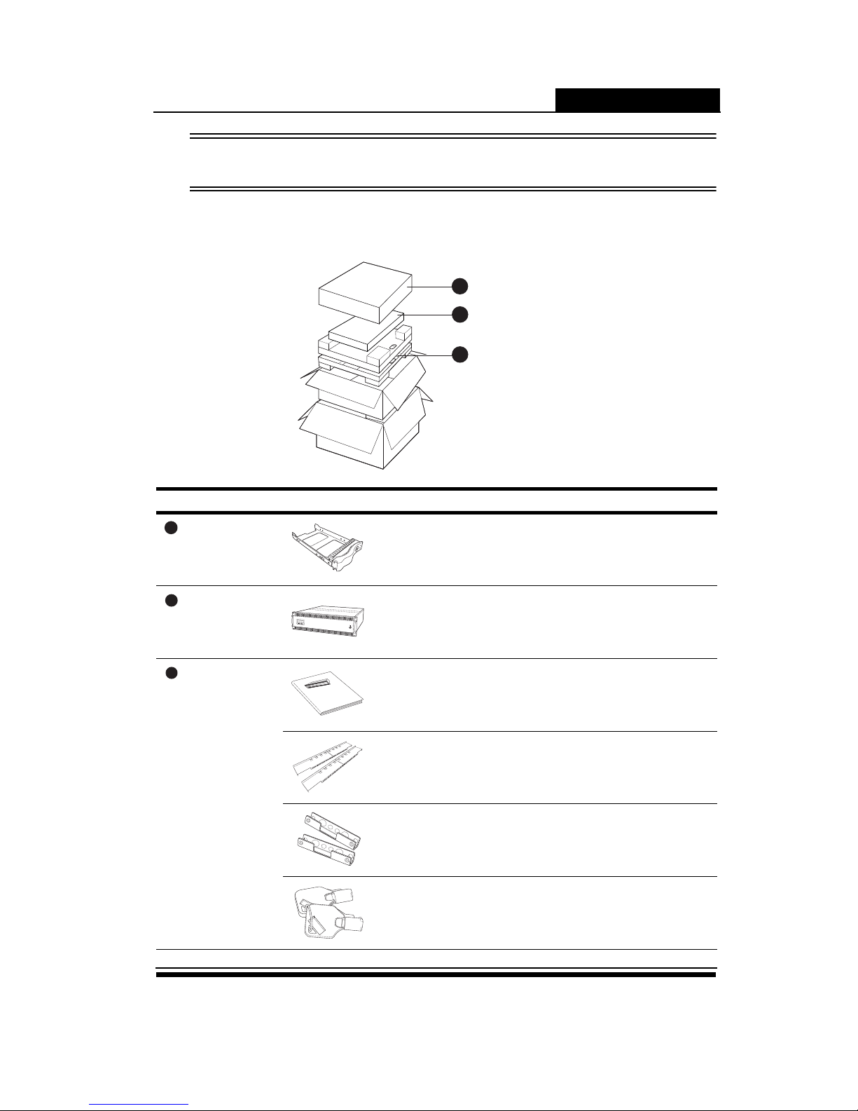
What’s in the box
Item qty
Disk Bo x
Hard D is k Tray 12-16 pc s (*1)
RAID Sy stem
Bo x
Disk A rr ay Syat em 1 pcs
Acc es sa ry Box
Quick In st allation Gu id e 1 pcs
Rail 1 set
Rail Ext en der 1 set
Front Pa ne l Key 2 pcs
1
Disk Box
3
Accessary Box
2
RAID System Box
1
2
3
Quick Installation Guide
Power P/S Fail Access
Enter ESC Pri/Sec
Page 10
ERP12R/S & ERP16R/S
2
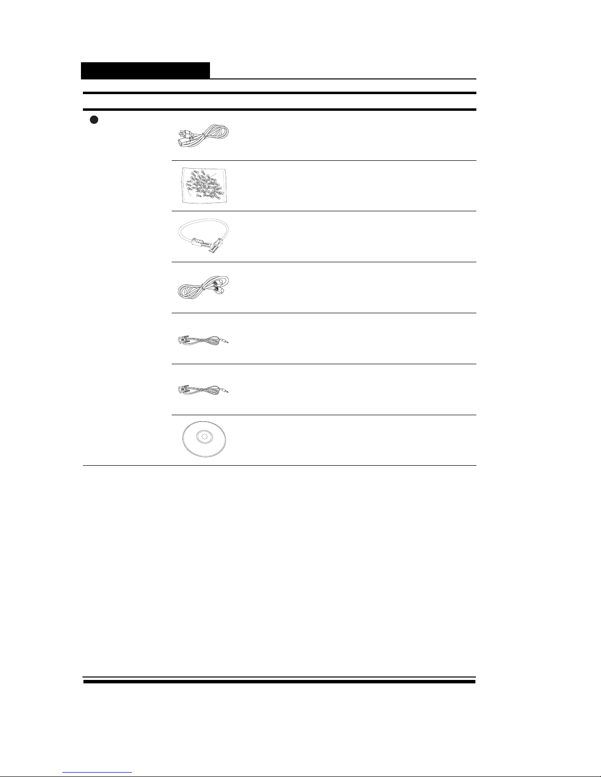
*1. The number of disk tray depends on what RAID model you purchased.
*2. 2 pieces for 2U/3U RAID system.
*3. 2 packs for 2U 12bays; 3 packs for 3U 16bays.
*4. 1 piece for single controller model; 2 pieces for redundant controller model.
*5. For 2U RAID system only.
Item qty
Acc es sa ry Box
Po we r Cable 2 pc s (*2)
Sc re w pa ck 2-3 pack s (* 3)
x4 S AS Cabl e (S FF -8808 t o SFF-880 8)
(For S AS RAID o nly)
1-2 pc s (*4)
Ethe rn et Cabl e 1-2 pc s (*4)
Term in al Cable (F em ale) 1-2 pc s (*4)
UP S Cable (Ma le ) 1 pc s (*5)
CD 1 pc s
3
Page 11
ERP12R/S & ERP16R/S
3
RAID System Components
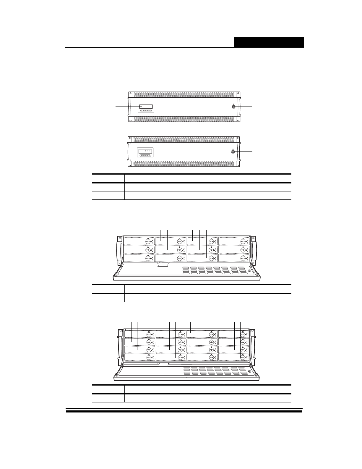
Front View
RAID System
JBOD
Open Front Panel
2U12bays
3U16bays
No Discription
1 LCD / Button Panel
2 Key Lock
No Discription
1-12 Hard Disk Tray 1-12
No Discription
1-16 Hard Disk Tray 1-16
1
2
Power
ID#
IO#1
Fan Temp HDD
RDY ACT RDY ACT
IO#2
1
2
1 2 3 4 5 6 7 8 9 10 11 12
1 2 3 4 5 6 7 8 9 1011 12 13 14 15 16
Page 12
ERP12R/S & ERP16R/S
4
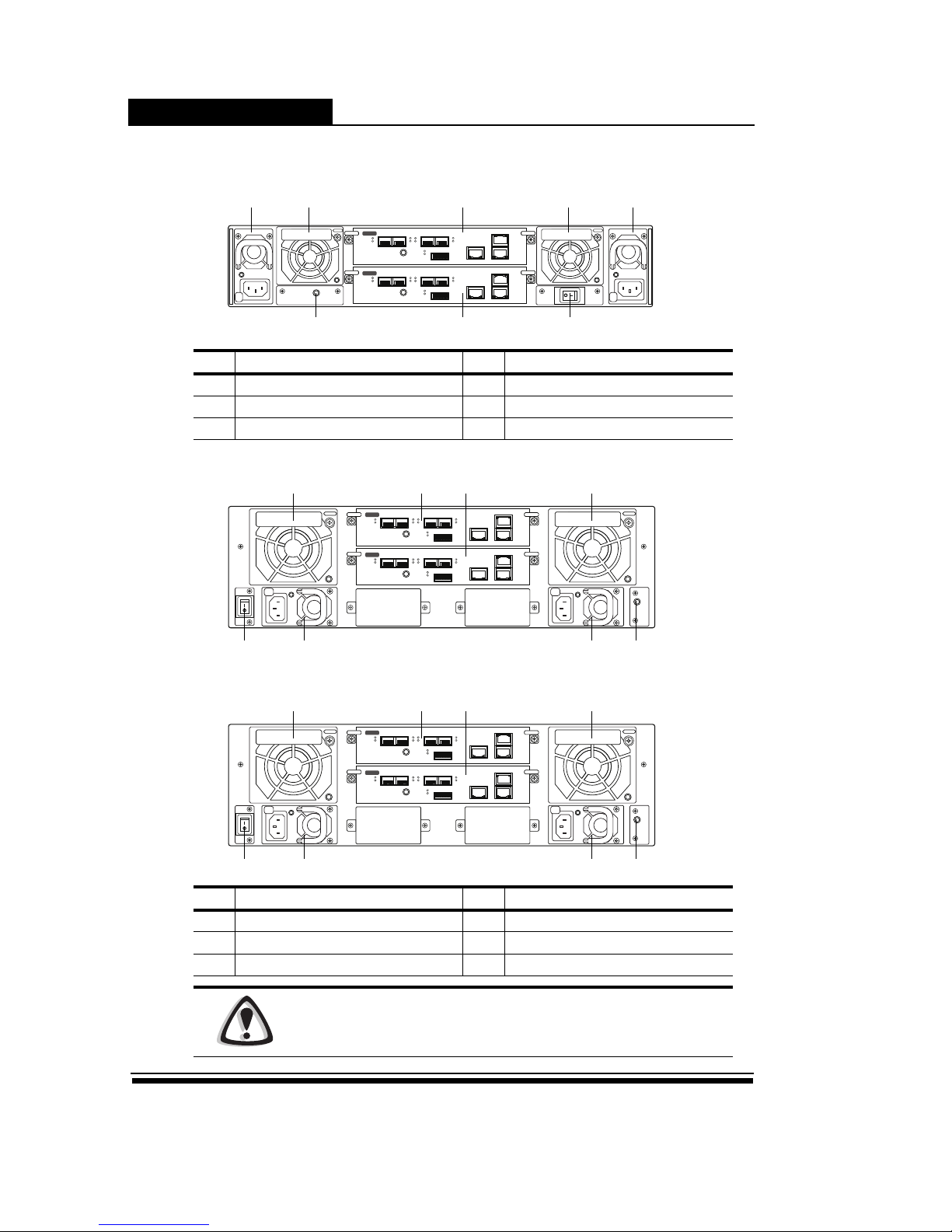
Rear View
2U12bays
3U16bays
3U16bays
No Description No Description
1 Hot-Swap Power Module 2 Hot-Swap FAN / Cache Guard Module
3 Hot-Swap Controller A / B 4 Power Switch
5 UPS Monitor Port
No Description No Description
1 Hot-Swap Power Module 2 Hot-Swap FAN / Cache Guard Module
3 Hot-Swap Controller A / B 4 Power Switch
5 UPS Monitor Port
Caution
DO NOT attempt to remove any component from the FAN / CacheGuard module
to avoid unexpected damage.
EXP
FC
iSCSILAN
1 2 3 4
EXP
FC
iSCSILAN
1 2 3 4
1 2 3
3
2 1
45
EXP
FC
iSCSILAN
1 2 3 4
EXP
FC
iSCSILAN
1 2 3 4
2 233
5114
EXP
FC
iSCSILAN
1 2 3 4
EXP
FC
iSCSILAN
1 2 3 4
2 233
5114
Page 13
ERP12R/S & ERP16R/S
5
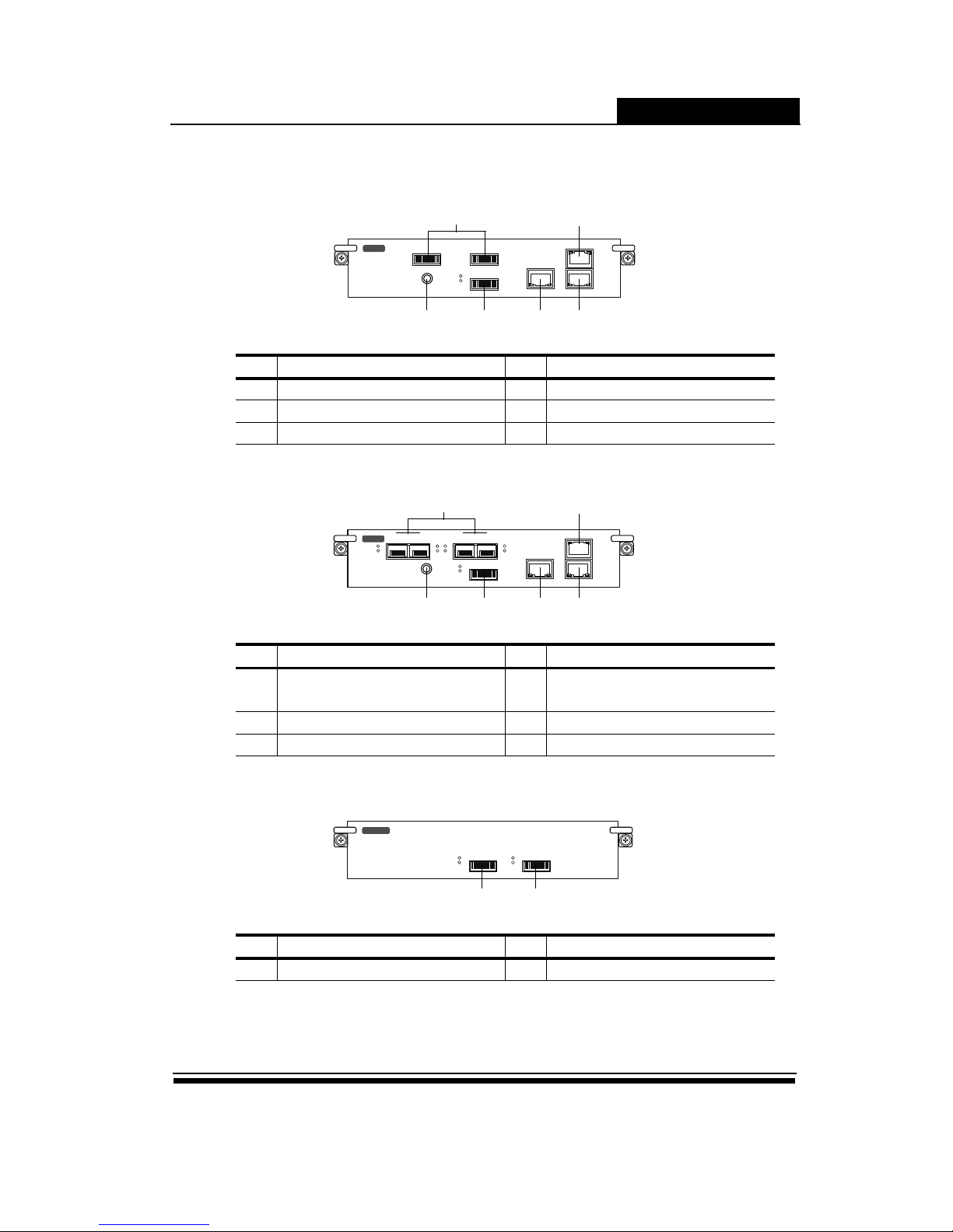
Controller Interface
SAS Interface
Fibre / iSCSI Interface
JBOD Interface
No Description No Description
1 6Gb SAS Channel Port 2 1Gb iSCSI Channel Port (RJ45)
3 LAN Port (RJ45) 4 SAS Expansion Port (SFF-8088)
5 Terminal Port 6 Heart Beat Indicator
No Description No Description
1
8Gb Fibre Channel Port
10Gb iSCSI Channel Ports
2 1Gb iSCSI Channel Port (RJ45)
3 LAN Port (RJ45) 4 SAS Expansion Port (SFF-8088)
5 Terminal Port 6 Heart Beat Indicator
No Description No Description
1 SAS Expansion Port (SFF-8088) 2 Host Channel
EXP
SAS
iSCSILAN
1 232
245
EXP
FC
iSCSILAN
1 2 3 4
1 2
3 245
EXP
JBOD
1 2
Page 14
ERP12R/S & ERP16R/S
6
Mounting the RAID System
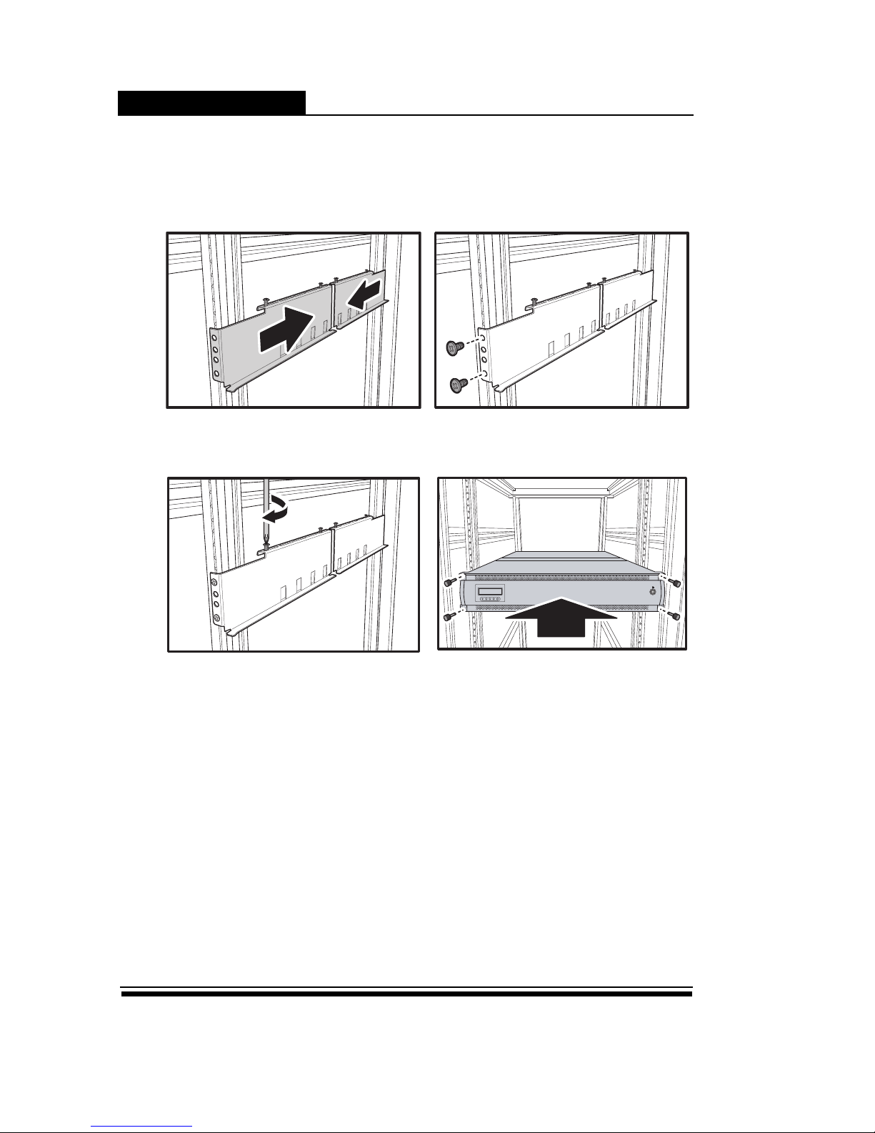
Installing the Slide Rail
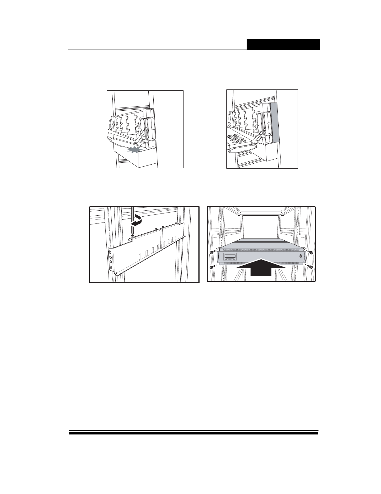
The RAID system/Rail Extenders can be installed in a standard 19-inch rack. Follow the procedures below:
1. Adjust the 4 screws making sure that correspond
with the mounting points on the rails.
2. Adjust the length of the rails as needed.
3. Secure the rails using two nuts and bolts on both
the front and back posts of the rack.
4. Tighten the lock screws. (If necessary, install the
extenders to move RAID system out a little.)
5. Slide the RAID system into the rack and secure it
into place using the fixing screws.
Page 15
ERP12R/S & ERP16R/S
7
Installing the Rail Extender
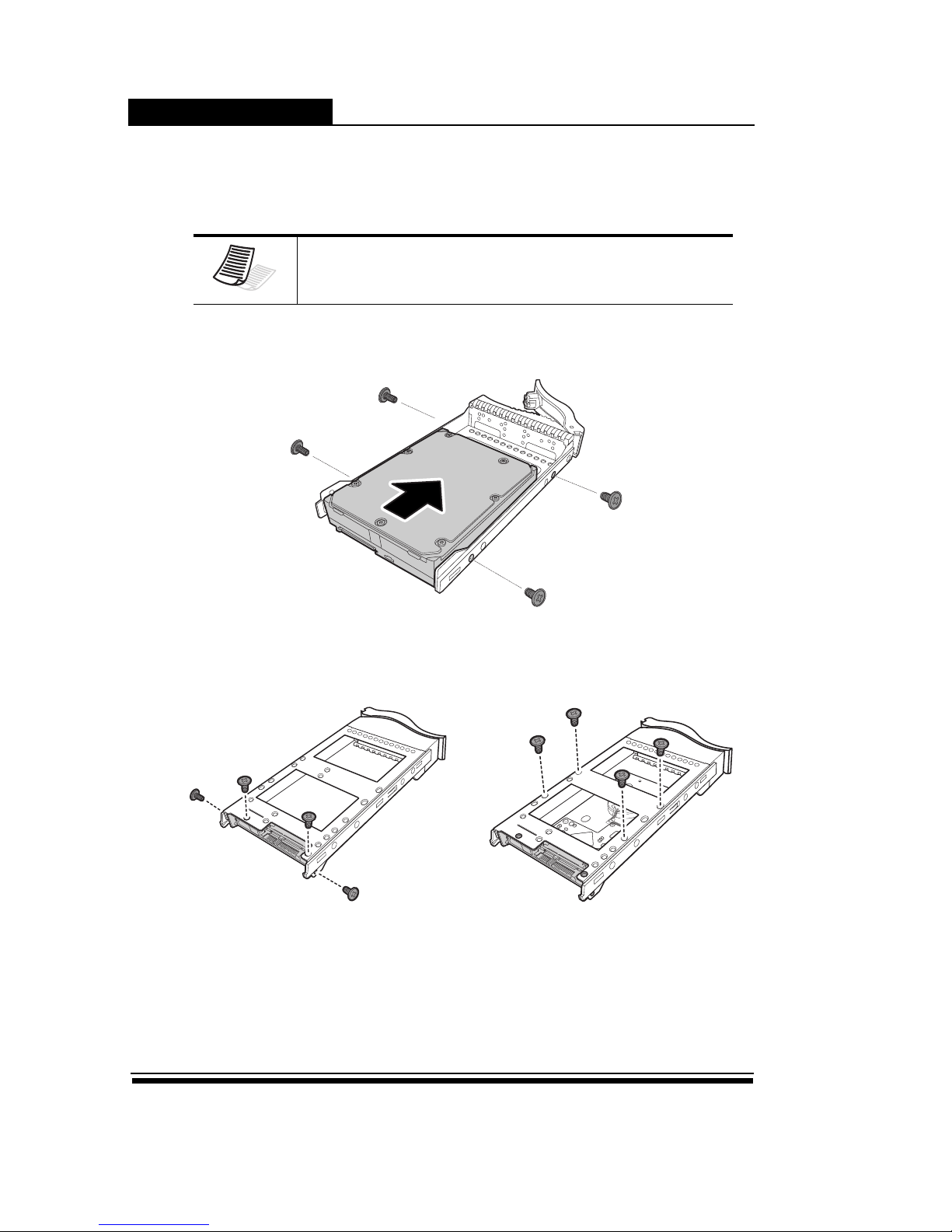
If the front door was stocked by abstacle chassis at botton side, please follow the procedures below to install
the rail extenders.
Follow the procedures below to install the rail extenders:
Without Rail Extender Installed Raid Extender
1. Install the rail extenders and attach the screws to
secure them.
2. Slide the RAID system into the rack and secure it
into place using the fixing screws.
Page 16
ERP12R/S & ERP16R/S
8
Installing Hard Disk
The RAID system supports SAS or SATA interface hard disks, follow the procedure below to install each hard
disk.
Installing the SAS Disk
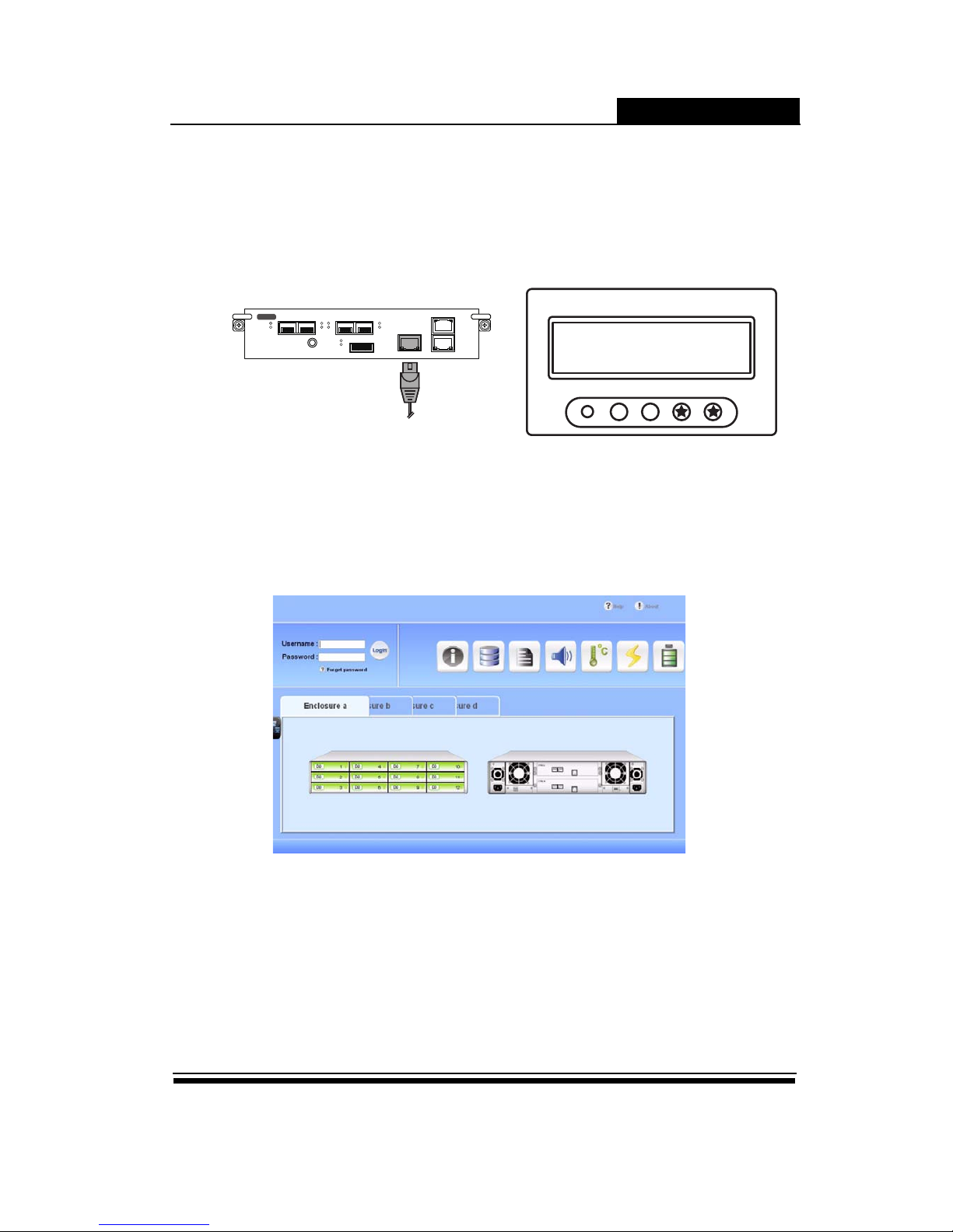
Insert the SAS hard drive into the disk tray and screw the sides to secure the hard disk, shown as below:
Installing the SATA Disk
SATA hard drive installation requires an AA-MUX adapter, which have to be installed on the hard disk tray
before installing the SATA hard disk, follow the procedure below:
Note
Recommend using enterprise edition hard disk in this RAID system for best performance and well data protection.
1. Place the AA-MUX adapter on the hard disk tray
and attach the four screws.
2. Insert the hard disk to connect to AA-MUX adapter,
attach the four screws to secure the hard disk.
Page 17
ERP12R/S & ERP16R/S
9
Configure RAID System by GUI
RAID system embeds a Graphic User Interface (GUI) that provides an easily way to monitor and configure the
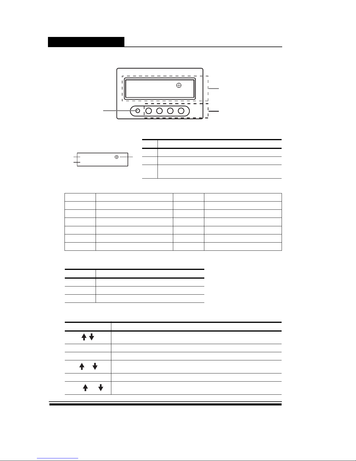
RAID system. You can open the GUI by a regular PC browser via LAN port. Follow the procedure below:
Set up the LAN connection
Quick Setup by GUI
Open a web browser and type in the IP address to open the GUI console as below.
Follow the procedure to quick setup RAID system;
1. Login as admin user. (Default user name is admin, password is 0000)
2. In menu [Quick Setup], select member disks and data security option.
3. Click Create to background initial disk array. You can connect to host server and start to use
RAID system. (Refer to GUI Operation Guide for more detail)
1. Attach the Ethernet cable to the LAN port on RAID
system.
2. Default is DHCP enable, press Enter and ESC but-
tons twice simultaneously, IP address will display
on LCD.
EXP
FC
iSCSILAN
1 2 3 4
192.168.1.123
Page 18
ERP12R/S & ERP16R/S
10
Understanding LCD Front Panel
LCD Panel
LED Definition
Button Function
No Description
1 Flash to indicate the RAID system is boot-up ready.
2 RAID system information, the maximum string length is 15.
3
Disks status (Disk1 is at left side), the maximum string length
is 16.
Symbols of disk status
Symbol Meaning Symbol Meaning
A
Adding disk
L
Local spare disk
B
Faulty disk
T
Clone target disk
# (No)
Member of Disk Group #
U
Unused disk (Global Spare)
F
Foreign / Conflict disk
W
SMART warning or BBR alert
G
Global spare disk
X
No disk
J
JBOD mode
?
Unreadable status
Color Description
Green Power on
Red Any event alert from the RAID system
Amber Host access
Key Description
View the previous and next status info message.
ESC Enter the menu mode or to escape or go back to previous menu
Enter To go to a submenu or to execute a selected option
+
Press twice simultaneous to mute if error beeper alert
ESC+Enter Display current IP address
ENT+ (or )
Display the previous (or next) enclosure system info information
192.168.1.1
0000000000000000
LED Button
LCD Panel
192.168.1.1
0000000000000000
12
3
Page 19
ERP12R/S & ERP16R/S
11
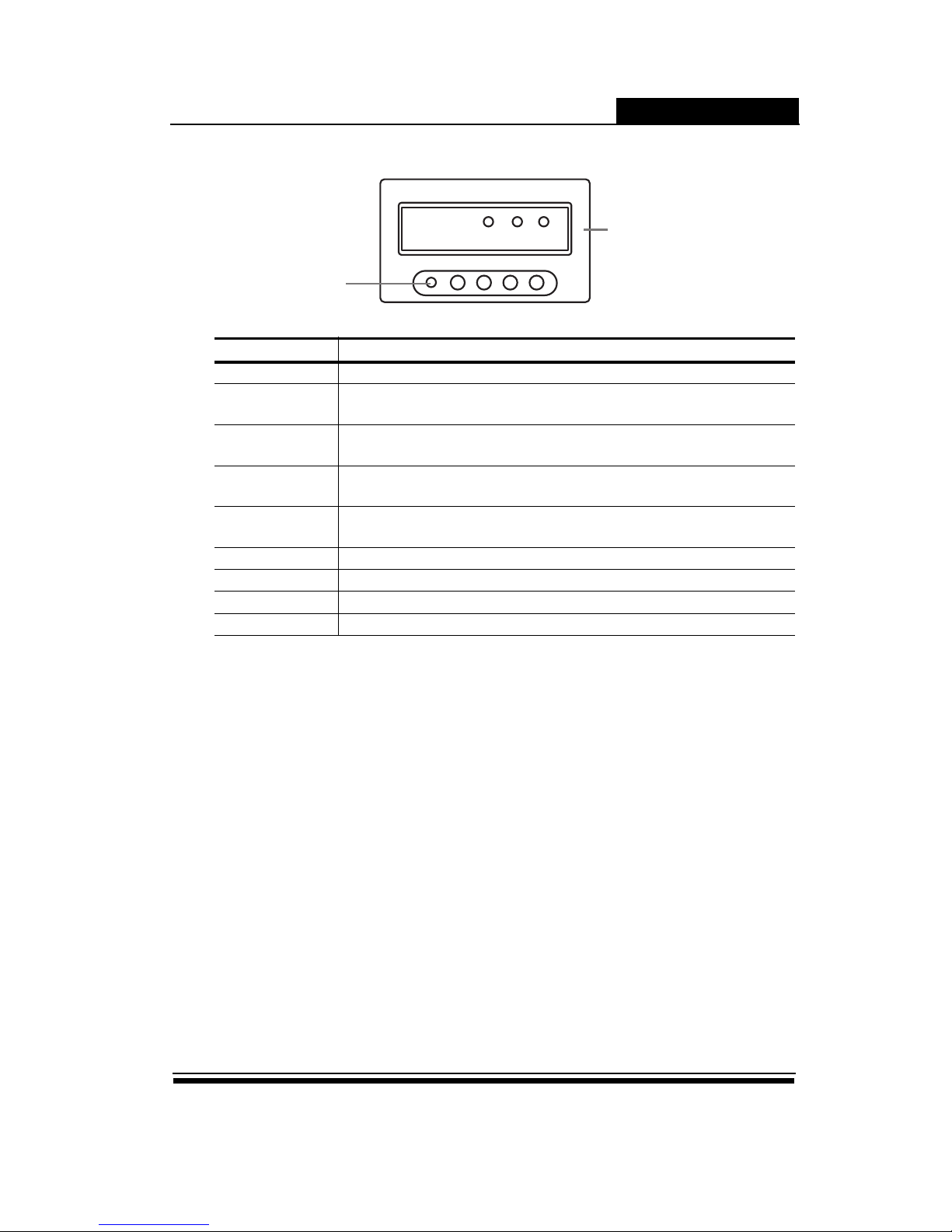
Understanding LCD Front Panel-JBOD
Key Description
7 Segment • Blue - It indicates the chassis ID.
Fan
• Green - Fan modules are installed and working properly.
• Red - This system has a fault Fan.
Temp
• Green - System temperature is working properly.
• Red - System temperature is abnormal.
HDD
• Green - Installed disk are working properly.
• Red - It shows the system has a fault hard disk.
Power
• Green - System power supplies are installed and working properly.
• Red - This system has a fault power supply.
IO#1 RDY • Blue - It indicates JBOD controller #1 is installed and working properly.
IO#2 RDY • Blue - It indicates JBOD controller #2 is installed and working properly.
IO#1 ACT • Blue (flash) - It indicates host is accessing the data via JBOD controller #1.
IO#2 ACT • Blue (flash) - It indicates host is accessing the data via JBOD controller #2.
Power
ID#
IO#1
Fan Temp HDD
RDY ACT RDY ACT
IO#2
LED
LCD Panel
 Loading...