


INSTALLATION AND OPERATING
INSTRUCTIONS FOR EASY HEAT IN-LINE
PIPE HEATING CABLE
Your heating cable has been designed to prevent water supply pipes from
freezing in winter. In addition, the heating cable has been designed for a quick,
easy and professional installation. State-of-the-art plumbing ttings, electrical
controls and heating cable have been provided to ensure a safe,economical
and long-lasting water line freeze protection.
These heating cables are primarily designed for use in water supply lines for
residential and commercial applications. Do not use this heating cable for other
types of applications without rst contacting Easy Heat Ltd. for professional
advice.
We recommend that the heating cable kit be installed by persons with adequate
knowledge of plumbing and electrical installations.
CAUTION – READ THIS BEFORE ATTEMPTING INSTALLATION
For 1.25” diameter Polyethylene
Water Pipes
Read carefully and follow these instructions for an efcient, safe and economical
installation. It is important that you assemble the proper tools and other supplies
(e.g. insulation, plumbing ttings, etc.) prior to beginning your heating cable
installation.
With proper installation, this heating cable will provide many years of trouble free
service. We recommend you retain these instructions for future reference.
USA
2 Connecticut South Drive
East Granby, CT 06026
www.easyheat.com
11001-062 Rev. 6 ©2015 Easy Heat
Tel: 800-537-4732
Fax: 800-541-7451
Canada
99 Union Street
Elmira, ON N3B 3L7
Tel: 800-794-3766
Fax: 800-361-4574

INSTALLATION AND OPERATING
INSTRUCTIONS FOR EASY HEAT
IN-LINE PIPE HEATING CABLE
LIMITED WARRANTY AND LIABILITY
Easy Heat warrants that if there are any defects in material or workmanship in this product
during the rst year after the date of its purchase, we will replace the product with an equivalent
model, not including any labor or other installation costs.
Our obligation to replace the product as described above is conditioned upon (a) the installation
of the product conforms to the specications set forth in our installation instructions and (b) the
product not having been damaged by unrelated mechanical or electrical activities.
Product replacement as described above shall be your sole and exclusive remedy
for a breach of this warranty. This limited warranty does not cover any service costs
relating to repair or replacement.
We shall not be liable for any incidental, special or consequential damages as a result of
any breach of this warranty or otherwise, whether or not caused by negligence. Some
states do not allow the exclusion or limitation of incidental or consequential damages, so the
above limitation or exclusion may not apply to you.
The warranty above is exclusive and makes no other warranties with respect to description or
quality of the product. No afrmation of fact or promise made by us, by words or action, shall
constitute a warranty. If any model or sample was shown to you, the model or sample was
used merely to illustrate the general type and quality of the goods and not to represent that the
goods would necessarily be of that type or nature. No agent, employee or representative of
ours has authority to bind us to any afrmation, representation or warranty concerning
the goods sold unless such afrmation, representation or warranty is specically
incorporated by written agreement.
Any implied warranty of merchantability or tness for particular purpose that may arise
in connection with the sale of this product shall be limited in duration to one year from
the date of purchase. We disclaim all other implied warranties, unless we are prohibited
by law from doing so, in which case all such implied warranties shall expire at the earliest
time permitted by applicable law. Some states do not allow limitations on how long an implied
warranty lasts, so the above limitation may not apply to you.
This warranty gives you specic legal rights, and you may also have other rights which vary
from state to state or province to province.
To obtain a replacement under this warranty any inoperative product or component must
be returned, with proof of purchase, to Easy Heat at the addresses noted herein. Buyer is
responsible for all costs incurred in removal and re-installation of product and must pre-pay
shipment to factory or point of purchase.
In Canada In USA
Heating Cable Warranty Department Heating Cable Warranty Department
99 Union Street 2 Connecticut South Drive
Elmira, ON N3B 3L7 East Granby, CT 06026

CAUTION – READ THIS BEFORE ATTEMPTING INSTALLATION
1. Do not attempt to pull the cable by the end connector; this connector
prevents the inltration of water into the cable, and excessive force could
damage this seal. The cable has been provided with a pull cord to ensure
that the cable is not damaged when being pulled through the piping.
2. The heating cable cannot be altered in length. Any attempt to physically
alter the heating cable will void the warranty. Once cut, the heating cable
cannot be repaired.
3. If the heating cable is insufciently exible to facilitate installation, perhaps
due to cold temperature, first completely uncoil the cable and then plug it
into a 120 VAC outlet until it is warm and pliable. The cable can then be
installed in the pipe. NEVER PLUG IN THE HEATING CABLE WHILE IT
IS COILED. If the heating cable touches itself while plugged in, as would
be the case if the cable is coiled, the outer PVC jacket will melt. This could
result in a loss of electrical insulation and, as the cable cools after it is
unplugged, the jacket will fuse together and the cable then could not be
uncoiled. A cable damaged in this manner must be discarded and is not
warranted.
4. Do not install heating cable in pipes that are heated to above 66°C
(155°F).
5. If the Ground Fault Circuit Interrupter (GFCI) trips during normal operation,
and cannot be reset, then there is likely a fault in the cable and the heating
cable system should not be energized. UNDER NO CIRCUMSTANCES
SHOULD THE GFCI BE BYPASSED.
6. The cable has been pre-assembled and sealed to the T-coupling; do not
alter the T-coupling connection as damage to the cable and/or coupling
could result.
WARNING
The plastic tting surrounding the black power supply cord is factory
tightened. If additional tightening of the tting is required to stop
leakage, do so in 1/8 turn increments. Overtightening may damage the
cord and result in electrical failure.
7. The heating cable must be installed straight inside the pipe and must not
touch, cross, or overlap itself at any point inside the water pipe, as this
could cause the cable to overheat and melt the cable (and/or the plastic
pipe). This could then result in a ground fault or short circuit, which would
require replacement of the cable.

List of Components
The following components are included in your in-line pipe heating cable kit:
• heating cable pre-assembled to T-coupling **Warning: The heating cable
has been pre-assembled and sealed to the T-coupling at the factory – do
not adjust these connections as damage to the T-coupling, cable and/or
seal may occur.
• stainless steel end connector clip.
• power control enclosure (SL1-G or SL2-G), includes thermostat and GFCI
receptacle.
• two tie-wraps (to attach thermostat sensor to pipe).
The longer lengths of heating cables are supplied on a convenient spool.
DO NOT REMOVE THE HEATING CABLE/T-COUPLING FROM THE CABLE
SPOOL.
In addition, you will require insulation and protective covering (to reduce wind chill
effect) for any exposed areas of pipe, an assortment of tools (e.g. electrician’s
sh tape), plumbing supplies, etc., depending on your specic installation.
Preparation for Installation of Heating Cable
This heating cable has been designed to prevent water supply pipes from
freezing. It is expected that the cable will be entirely inserted into 11/4” diameter,
buried and/or insulated, polyethylene water piping. In addition, if the cable is
being installed in a pressurized pipe, it is recommended that the maximum
system pressure be less than 60 psig. The heating cable life expectancy can
be extended if the cable is installed in non-pressurized piping. For example, the
installation of a check valve at the suction port of a jet pump will ensure that the
suction piping is not pressurized; hence, a heating cable in the suction piping
will not be subjected to system pressure.
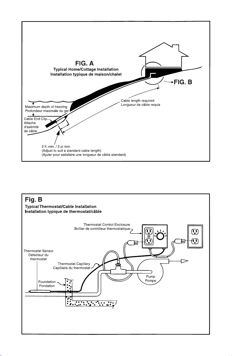
The heating cable inside the pipe should extend beyond the furthest point of
the pipe, which would, if unheated, be expected to freeze in winter. The pipe
itself can, if necessary, further extend beyond the end of the cable. Refer to
Figure A.
It is not possible to alter the length of the cable to accommodate a nonstandard
length of piping. These heating cables are available in a wide variety of standard
lengths; ensure that the cable you have chosen for your installation is of
appropriate length.

The insulation of the complete length of the outdoor piping is optional, except
in areas of extreme cold. Insulation of the piping is best accomplished by the
use of a maximum of 1/2” thick polyethylene foam (PEF) insulation, such as
the “Tundra®” insulation available at most hardware stores. (Unlike berglass,
polyethylene foam insulation is not affected by water). The addition of the 1/2”
thick PEF jacket will greatly improve the freeze protection capability and energy
efciency of any installation; the associated energy savings and enhanced pipe
freeze protection will more than offset the small cost of that insulation.
WARNING: Never use more than ½” thick polyethylene foam (PEF) or other
equivalent non-ammable insulation. Over insulation can cause the heating
cable to overheat and cause serious re hazard or electrical shock.
If uninsulated, the water supply pipe should be buried in at least 3” of topsoil or
sand. Any sections of pipe exposed to the elements should be insulated and
protected from wind, as the “wind chill factor” can be a serious impediment to
the performance of the heating cable. For example, a large drainpipe can be
used to protect the water pipe from wind chill effects and from such damage as
may occur due to, for example, ice movement at the water shore.
Insulation of underwater piping can present signicant problems, primarily due to
the fact that PEF insulation is quite buoyant and will tend to make the water pipe
oat on the surface of the water. This can be overcome by attaching weights, such
as steel or concrete, to the insulated piping. In general, insulation of underwater
piping is probably not necessary below about the 1 foot water depth.
It is recommended that the in-line pipe heating cable system be energized at
all times during the winter season such that water supply pipes do not freeze.
(During warmer winter periods, the thermostat control will automatically
disconnect power from the heating cable to minimize energy consumption). In
the event that the water pipe freezes, such as might happen during an electrical
power interruption, it might take a few hours to thaw a frozen pipe once power is
restored, depending on the weather conditions, duration of power outage, etc.
It is not recommended that the cable be used to regularly thaw uninsulated
frozen pipes. If power outages of 24 hours or more are frequently expected,
or if the cable is to be used to regularly thaw frozen pipes, it is recommended
that the complete length of outdoor piping be insulated.
The heating cable must only be plugged into the receptacle in the power control
enclosure. Hence, the power control enclosure must be mounted in close
proximity to the cable exit from the T-coupling. Refer to Figure B. Ideally, the
power control enclosure should be located within 10 ft of the estimated coldest
point of the water pipe such that the thermostat sensor can be attached there.
This ensures that heat is always applied to the pipe as required to ensure that
the coldest point does not freeze.

If it is not possible to locate the power control enclosure within 10 ft of the
estimated coldest point of the water pipe, the thermostat adjustment capability
can compensate for this. In such a case, however, the thermostat sensor must
be installed onto a section of the piping, which is expected to be reasonably
cold. In a typical installation of a home/cottage located on a lake with a rocky
shoreline, the piping on the outside of the cottage/home foundation could usually
be expected to be reasonably cold, even though not as cold, perhaps, as the
piping at the rocky lakeshore. Attaching the thermostat sensor to the piping
immediately outside the building foundation and increasing the thermostat
setpoint will still enable the thermostat control to keep the coldest section of
piping from freezing while minimizing energy consumption. Refer also to the
section “Operation of the Heating Cable”.
It is recommended that the power control enclosure and the T-coupling be
mounted in a dry area where no damage will occur to the water line heating
system connections. The T-coupling should be located as close as possible to
the pump, but more importantly, in close proximity to the location of the power
control enclosure. It is suggested that the pumping system be located in a
heated area, as the pump and associated downstream piping must also be
protected from freezing.
Another factor in establishing the location for the power control enclosure should
be the requirement to regularly test the GFCI. Also, the possibility of the heating
cable becoming inadvertently unplugged should be considered. The power
control enclosure contains a GFCI, and hence it is not necessary for this control
to be connected to a GFCI protected outlet. However, it is possible to plug the
power control enclosure into a GFCI protected receptacle, if convenient.
It is recommended that the heating cable be the only load on the circuit supplying
electrical power to the cable.

Installing the Heating Cable
1. Check Piping
Before installing the heating cable, ensure that all joints and inside surfaces
of the pipe are free from any sharp edges or other restrictions which would
inhibit pulling the cable through the pipe or which may damage the heating
cable jacket.
2. Prepare Cable
For cables supplied on spools, remove the power control enclosure from the
center of the spool. (You may nd it benecial to mount the spool on some
convenient axle, such as a broom handle, for easier dispensing).
For cables supplied without spools, uncoil and straighten.
3. Lubricate Cable
You will nd installation easiest in straight lengths of piping; piping with
several 90 degree turns will signicantly restrict the threading of the cable
through the piping; a pull force exceeding 30 lbs. could damage the cable.
Similarly, long piping runs exceeding about 100 feet may also require
excessive force to pull the cable; in such situations, it is recommended that
the piping be lled with water as this provides excellent lubrication for pulling
the cable through the pipe. As an alternate, the cable can be lubricated with
petroleum jelly; do not use any other type of lubricant, as this could
damage the cable and/or result in contamination of the water flowing
through the pipe. It is also advantageous to keep the heating cable as
straight and free from twists and kinks as possible.
4. Thread Cable
Thread heating cable through any plumbing ttings, which may be necessary
to connect the T-coupling to the piping. Refer to Figure C.
5. Attach Pull Cord
Attach the heating cable pull cord to a strong cord or electrician’s sh-tape
which has been threaded through the pipe. It is recommended that tape
be applied around the cable end connector and cord to ensure the end
connector does not get snagged on the inside of the pipe. Do not loop
the heating cable back onto itself for pulling purposes, as this could
damage the heating elements inside the cable. Refer to Figure C. Do
not attach the fish tape directly to the cable end connector.
6. Pull Cable
Gently pull (maximum pull force of 30 lbs) the heating cable through the
water pipe. Remove the T-coupling from the spool hub when the cable is
fully uncoiled from the spool. Disconnect the sh-tape or cord.
7. Secure End Connector
Secure the cable end connector to the piping using the stainless steel clip
provided. Refer to Figure D. Insert the clip through the hole in the cable
end connector. Note that the pull cord does not have to be removed from
the heating cable; the cord and shrink sleeve are “food grade” quality and
can be safely left inside the pipe.

DO NOT ATTEMPT TO REMOVE THE HEAT SHRINK FROM THE CABLE
AS DAMAGE TO THE CABLE MAY RESULT. If desired, the cord can
be cut at either end of the shrink sleeve. Complete associated plumbing
connections.
8. Check Cable
Plug the cable into a 120 VAC outlet to ensure that the cable was not
damaged during installation; the cable should feel warm within one minute
of being energized. Once the cable warmth is detected, unplug the cable
and proceed with installation.
9. Connect T-coupling
Connect the T-coupling to the pipe and complete all plumbing connections,
ensuring that the cable inside the pipe does not touch, cross, or overlap
itself at any point inside the water pipe.
10. Check Cable
It is recommended that the continuity of the cable be tested at this time
to ensure that the cable was not damaged during the completion of the
plumbing connections. Do not plug in the cable in anticipation of sensing
the warming of the piping, as this could take a signicant amount of time
and may not even be noticeable, depending on the weather conditions,
pipe insulation, etc.
Installing the Power Control Enclosure
1. Mount
Mount the power control enclosure in a suitable location as noted in
“Preparation for Installation of Heating Cable” above. Using nylon tie wraps
supplied with the heating cable, attach the thermostat sensor to the pipe.
If this section of pipe is insulated, it is important that the sensor be placed
directly on the pipe and then covered by the insulation.
2. Pressurize
The water supply system should then be returned to normal operation and
all pipes completely lled with water. The power control enclosure can then
be plugged into a properly grounded electrical receptacle.
3. Energize
Plug the heating cable into the receptacle on the power control enclosure
and turn the thermostat control knob to the maximum setting.
4. Adjust
If you are certain that the thermostat sensor was located at the coldest
point of the piping, then set the thermostat temperature control knob to the
minimum setpoint. Otherwise, it is advisable to increase the thermostat
setting somewhat above the minimum setpoint.

Operation of the Heating Cable
Normally, the heating cable does not require any monitoring or adjustment;
the thermostat provided with the cable ensures that the cable is only turned on
when required, i.e. in winter. At all other times, the cable will not be energized
and, hence, minimum energy consumption is assured. Still, it is advisable to
unplug the cable in nonwinter seasons.
If an electrical power failure occurs for longer than a few hours, the water supply
pipe might freeze; this freezing will not damage the heating cable. If power
interruptions are expected to be longer than a few hours in duration, though, and
if such power failures are expected to occur frequently, increasing the thermostat
setpoint can, to some extent, help counteract the effect of power interruptions.
(The higher thermostat setpoint keeps the water in the pipe warmer, thereby
increasing the amount of time required to freeze the water in the pipe during
a power interruption).
If the water pipe should freeze during normal operation, then this likely means
that the thermostat sensor was not located at the coldest portion of the pipe;
this can usually be overcome by simply increasing the thermostat temperature
setting i.e. the thermostat sensor may not necessarily have to be relocated.
The GFCI receptacle contains a pilot light; this light is only illuminated when a
fault on the heating cable is detected.
To test if the power control enclosure is functioning properly and that 120 VAC
power is available, turn the thermostat control knob to the maximum setting,
plug in a 120 VAC powered device such as a light xture. The device should be
energized, in the case of a light xture illuminated.
It is recommended to inspect the thermostat control and its connection to the
electrical power source at the beginning of the heating season and monthly
during operation. Similarly, check the GFCI. Testing of the GFCI is dependent
upon the temperature of the capillary bulb.
a) If the ambient is below 21° C (69.8° F), turn the thermostat control knob
to the maximum setting; the GFCI will be energized. Push the “TEST”
button on the GFCI receptacle; a “ click “ sound should be heard and the
receptacle indicator light will turn on. Push the “ RESET “ button on the
GFCI receptacle to reset the power (the indicator light will turn off).
b) If the ambient temperature is above 22° C (71.6° C), you will need to
“cool down “ the capillary bulb to test the GFCI. It is recommended to wait
until the bulb is below 21° C (69.8° F) as in step a), however if this is not
possible you will need to submerge the capillary bulb in ice water for 10
minutes and then follow the instructions as described in a) above.
c) The GFCI will not be affected by power interruptions.


NOTES

INSTRUCTIONS D’INSTALLATION
ET DE FONCTIONNEMENT CÂBLE CHAUF-
FANT POUR CONDUIT EN LIGNE EASY HEAT
Ce câble chauffant a été spécialement conçu pour éviter que les conduits
d’amenée d’eau ne gèlent en hiver et pour permettre une installation rapide,
facile et professionnelle. Les raccords de tuyauterie, les contrôles électriques
et le câble chauffant dernier cri doivent procurer une protection sécuritaire,
économique et durable contre le gel des conduits d’eau.
La câble chauffant a surtout été conçu pour des applications résidentielles et
commerciales. Ne pas l’utiliser pour d’autres genres d’applications avant d’avoir
demandé des conseils aux experts de Easy Heat Ltd.
Nous recommandons l’installation de l’ensemble de câble chauffant par des
personnes ayant les connaissances appropriées dans les domaines de la
plomberie et des installations électriques.
ATTENTION – LIRE LES PRÉSENTES INSTRUCTIONS AVANT
L’INSTALLATION
Pour conduits d’eau en polyéthylène
diamètres de 1,25 po
Lire attentivement les instructions suivantes pour une installation efcace,
sécuritaire et économique. Il est important d’assembler les outils appropriés
et les autres fournitures (par ex., isolant, raccords de tuyauterie, etc.) avant
d’installer le câble chauffant.
S’il est installé comme il faut, ce câble chauffant fonctionnera longtemps, sans
le moindre problème. Veuillez garder ces instructions à titre de référence.
USA
2 Connecticut South Drive
East Granby, CT 06026
www.easyheat.com
11001-062 Rev. 6 ©2015 Easy Heat
Tel: 800-537-4732
Fax: 800-541-7451
Canada
99 Union Street
Elmira, ON N3B 3L7
Tel: 800-794-3766
Fax: 800-361-4574

INSTRUCTIONS D’INSTALLATION
ET DE FONCTIONNEMENT CÂBLE CHAUF-
FANT POUR CONDUIT EN LIGNE EASY HEAT
GARANTIE ET RESPONSABILITÉ LIMITÉES
Easy Heat garantit que s’il y a des défauts de matériel ou de main-d’oeuvre dans ce produit
pendant la première année de son achat, il remplacera le produit avec un modèle équivalent,
sans inclure les coûts de main-d’oeuvre et d’installation.
Notre obligation de rembourser le produit comme décrit ci-dessus est conditionnée à (a)
l’installation du thermostat conformément aux spécications exposées dans nos directives
d’installation et (b) ce que le thermostat n’ait pas été endommagé par des activités mécaniques
ou électriques indépendantes.
Le remplacement du produit décrit ci-dessus sera votre seul et exclusif recours pour
une violation de cette garantie. Cette garantie limitée ne couvre aucun coût relatif à la
réparation ou au remplacement.
Nous ne serons pas responsable des dommages accessoires, spéciaux ou indirects,
à la suite de toute violation de cette garantie ou autrement, qu’ils soient causés par la
négligence ou non. Certains États ou provinces n’autorisent pas l’exclusion ou la limitation
des dommages accessoires ou indirects; par conséquent, la limitation ou l’exclusion ci-dessus
pourrait ne pas s’appliquer à vous.
La présente garantie ne fait aucune autre garantie en ce qui concerne la description ou la
qualité du produit. Aucune afrmation de fait ou de promesse verbale ou par acte ne constituera
une garantie. Si un modèle ou un échantillon vous a été montré, le modèle ou l’échantillon
a été utilisé simplement pour illustrer le caractère général des biens et non pour représenter
le fait que les biens seront nécessairement de ce type ou de cette nature.
Aucun de nos agents, employés ou représentants n’a le pouvoir de nous lier à toute
afrmation, représentation ou garantie concernant les biens vendus, à moins qu’une
telle afrmation, représentation ou garantie ne soit spéciquement incorporée dans
une entente écrite.
Toute garantie implicite de qualité marchande ou d’adéquation à des ns particulières,
qui pourrait survenir en relation avec la vente de ce produit, sera limitée en durée à un
an à partir de la date d’achat. Nous désavouons toute autre garantie implicite, à moins
que la loi ne nous l’interdise. Dans ce cas, toutes ces garanties implicites expireront au moment
le plus rapproché permis par la loi applicable. Certains États ou provinces n’autorisent pas
les restrictions sur la durée d’une garantie implicite; par conséquent la restriction ci-dessus
pourrait ne pas s’appliquer à vous.
Cette garantie vous accorde des droits spéciques reconnus par la loi, mais elle peut également
accorder d’autres droits, puisqu’ils varient d’un État ou d’une province à l’autre.
Pour obtenir un remboursement en vertu de cette garantie, veuillez retourner le produit ou
composant défectueux avec preuve d’achat, port payé, à Easy Heat aux adresses qui se
trouvent dans le présent document. L’acheteur est responsable pour tout coût encourru dans
l’enlèvement et la réinstallation du produit.
Au Canada aux États-Unis
Heating Cable Warranty Department Heating Cable Warranty Department
99 Union Street 2 Connecticut South Drive
Elmira, ON N3B 3L7 East Granby, CT 06026

ATTENTION – LIRE CES INSTRUCTIONS AVANT L’INSTALLATION
1. Ne pas essayer de tirer sur le câble par le connecteur d’extrémités;
ce connecteur empêche l’inltration d’eau dans le câble, et l’utilisation
excessive de force pourrait nuire à I’étanchéité. Le câble est muni d’une
corde pour éviter qu’il ne soit endommagé quand on tire sur lui pour le faire
passer à travers le conduit.
2. La longueur du câble chauffant ne peut être modifiée. Toute tentative
de modication physique du câble chauffant annule la garantie. Une fois
coupé, le câble chauffant ne peut plus être réparé.
3. Si le câble chauffant n’est pas sufsamment souple pour faciliter l’installation,
peut-être en raison de basses températures, d’abord dérouler le câble et
ensuite le brancher sur une prise de courant de 120 VCA jusqu’à ce qu’iI
soit chaud et exible. Le câble peut alors être instaIIé dans le conduit. NE
JAMAIS BRANCHER LE CÂBLE CHAUFFANT QUAND IL N’EST PAS
DÉROULÉ. Si une partie du câble chauffant touchait une autre partie du
même câble alors qu’iI est branché, comme ce serait le cas si le câble n’était
pas dérouIé, son enveloppe de PVC fondrait. Cela pourrait entraîner une
perte d’isolation électrique et, étant donné que le câble refroidit après être
débranché, I’enveloppe fond et le câble ne peut plus être déroulé. Si un
câble est endommagé ainsi, il faut s’en débarrasser. Dans ce cas, il n’est
pas garanti.
4. Ne pas installer le câble chauffant dans des conduits chauffés à plus
de 66°C (155°F).
5. Si l’interrupteur différentiel saute pendant le fonctionnement normal et qu’iI
ne puisse être remis en état, le câble est vraisemblablement défectueux
et le système ne peut être mis sous tension. EN AUCUN CAS, METTRE
HORS CIRCUIT L’INTERRUPTEUR DIFFÉRENTIEL.
6. Le câble a été préassemblé et sceIIé au raccord en T; ne pas modifier la
connexion du raccord en T vu que le câble et/ou le raccord pourraient
être endommagés.
ATTENTION
Le recouvrement de plastique, entourant le cordon électrique est ajusté
à l’usine. Si un ajustement additionnel est requis an d’arrêter une fuite,
tourner 1/8 de tour à la fois. Un serrement excessif peut endommager
le cordon et causer une panne électrique.
7. Le câble chauffant doit être installé dans le conduit de façon droite et ne
peut se toucher, se croiser ni se chevaucher à aucun endroit dans le
conduit d’eau parce qu’iI pourrait surchauffer et ainsi fondre (et/ou faire
fondre le conduit en plastique). Cela pourrait entraîner un défaut à la terre
ou un courtcircuit, ce qui nécessiterait le remplacement du câble.

Liste d’articles
Voici une liste des articles que comprend la trousse du câble chauffant pour
conduit en ligne:
• câble chauffant préassembIé au raccord en T. ** Attention : le câble chauffant
a été préassembIé et scelIé au raccord en T à l’usine; ne pas essayer
de rajuster ces connexions parce que le raccord en T, le câble ou le joint
d’étanchéité pourraient être endommagés.
• attache d’extrémité du câble en acier inoxydable.
• boîtier de commande mécanique (SL1-G) : comprend le thermostat et la
prise de courant de l’interrupteur différentiel.
• deux attaches autoblocantes (pour xer le détecteur du thermostat au
conduit).
Les câbles chauffants longs sont fournis en bobine.
NE PAS ENLEVER LE CÂBLE CHAUFFANT OU LE RACCORD EN T DE
LA BOBINE.
De plus, il vous faudra du matériau isolant et un revêtement protecteur (an de
réduire l’effet du facteur éolien) pour toute partie de conduit qui est exposée
aux intempéries, ainsi qu’un jeu d’outils (par exemple, un ruban de tirage), des
accessoires de plomberie, etc., selon l’installation.
Préparation de l’installation du câble chauffant
Ce câble chauffant a été spécialement conçu pour empêcher les conduits
d’amenée d’eau de geler. Pour cela, on suppose que le câble est entièrement
introduit dans des conduits d’eau enfouis et/ou isolés, en polyéthylène, d’un
diamètre de 1,25 po. De plus, si le câble est installer dans un conduit sous
pression, nous recommandons une pression maximale inférieure à 60 lb/po2.
La durée de vie du câble chauffant peut être prolongée s’il est instalIé dans des
conduits qui ne sont pas mis sous pression. Par exemple, l’installation d’une
soupape de retenue à l’orice d’aspiration d’une pompe à injection assure que
les tuyaux d’aspiration ne sont pas mis sous pression; en conséquence, le
câble chauffant des tuyaux d’aspiration ne sera pas assujetti à de la pression
d’alimentation.
Le câble chauffant dans le conduit doit dépasser le point le plus recuIé du
conduit, qui, s’il n’est pas chauffé, pourrait geler en hiver. Le conduit même
peut dépasser, au besoin, I’extrémité du câble. Voir g. A.
Il est impossible de modier la longueur du câble pour I’adapter à un conduit
d’une longueur non standard. Ces câbles chauffants sont vendus en plusieurs
longueurs standard; s’assurer que le câble choisi a la longueur appropriée,
pour l’installation.

L’isolation d’un conduit pour l’extérieur sur toute sa longueur est facultative, sauf
pour des endroits où il fait extrêmement froid. Le conduit est isoIé le mieux au
moyen d’un demi-pouce (au maximum) de mousse isolante en polyéthylène,
comme l’isolant « Tundramd » vendu dans la plupart des quincailleries.
(Contrairement à la bre de verre, la mousse isolante en polyéthylène résiste
à l’eau.) L’ajout de l’enveloppe en mousse isolante en polyéthylène, d’une
épaisseur de 1/2 po, augmentera de beaucoup la protection du gel et le
rendement énergétique de toute installation; les économies d’énergie et la
protection améliorée du conduit contre le gel compense amplement le coût
modique de l’isolant.
MISE EN GARDE : N’utiliser jamais un d’isolation de mousse de polyéthylène
(DEP) ou autre équivalent non inammables isolation a une épaisseur excédant
1/2 pouces. Plus d’isolation peut causer le câble chauffant à se surchauffer et
causer un sérieux risque de choc électrique et d’incendie.
S’il n’est pas isolé, le conduit d’amenée d’eau doit être enfoui dans au moins
3 po de terre ou de sable. Toute partie exposée aux intempéries doit être isolée
et protégée contre le vent, vu que le facteur éolien peut réduire considérablement
le rendement du câble chauffant. Par exemple, on peut utiliser un gros tuyau de
drainage pour protéger le conduit d’eau des effets du vent et des dommages
causés par exemple par le mouvement des glaces sur le rivage.
L’isolation de conduits submergés peut poser de sérieux problèmes, surtout
parce que la mousse isolante en polyéthylène otte assez bien et aura tendance
à faire monter le conduit d’eau à la surface. Pour y remédier, on peut attacher
des poids, comme de I’acier ou du béton, au conduit isolé. En général, il se
peut que l’isolation d’un conduit submergé ne soit pas nécessaire s’il se trouve
à une profondeur de plus d’un pied.
Nous recommandons qu’en hiver, le câble chauffant du conduit en ligne soit
mis sous tension en tout temps pour que les conduits d’amenée d’eau ne
gèlent pas. (En hiver, pendant des périodes relativement chaudes, le contrôleur
thermostatique débranchera automatiquement le câble chauffant an de réduire
au minimum la consommation d’électricité.) Au cas où un conduit d’eau gèlerait,
par exemple pendant des pannes d’électricité, le dégel d’un tel conduit pourrait
prendre quelques heures une fois la panne réparée, selon les conditions
atmosphériques, la durée de la panne, etc. L’utilisation régulière du câble pour
dégeler des conduits gelés non isolés n’est pas recommandée. Si l’on s’attend
à des pannes d’électricité fréquentes de 24 heures ou plus ou si le câble est
utilisé régulièrement pour dégeler des conduits gelés, nous recommandons
l’isolation des conduits se trouvant à l’extérieur sur toute leur longueur.

Le câble chauffant peut uniquement être branché sur la prise de courant du
boîtier de commande mécanique. En conséquence, le boîtier de commande
mécanique doit être monté près de l’endroit où le câble sort du raccord en T.
Voir g. B. Idéalement, le boîtier de commande mécanique devrait être situé
à moins de 10 pieds de l’endroit du conduit d’eau considéré comme étant le
plus froid, de sorte que le détecteur du thermostat peut y être xé. Ainsi, l’on
s’assure que le conduit est toujours sufsamment chaud pour que la partie la
plus froide ne gèle pas.
S’il n’est pas possible d’installer le boîtier de commande mécanique à moins de
10 pieds de l’endroit du conduit d’eau considéré comme étant le plus froid, le
pouvoir d’ajustement du thermostat peut y remédier. En tel cas, cependant, le
détecteur du thermostat doit être installé sur la partie du conduit dont on prévoit
qu’elle sera raisonnablement froide. Prenons comme exemple une maison ou
un chalet construit près d’un lac à rivage rocheux. L’on pourrait s’attendre à
ce que les conduits à l’extérieur de la fondation du chalet ou de la maison soit
raisonnablement froids, mais peut-être pas aussi froids que les conduits sur le
rivage rocheux. Si l’on xe le détecteur du thermostat au conduit immédiatement
à l’extérieur de la fondation du bâtiment et que l’on augmente la valeur de
consigne du thermostat, le contrôleur thermostatique pourra empêcher le gel de
la partie la plus froide du conduit, tout en consommant le minimum d’électricité.
Se reporter aussi à la partie intitulée « Fonctionnement du câble chauffant ».
Il est recommandé que le boîtier de commande mécanique et le raccord en T
soient montés dans un endroit sec où les connexions du système de chauffage
en ligne ne peuvent être endommagées. Le raccord en T doit se situer le plus
près possible de la pompe, mais, qui plus est, près de l’emplacement du boîtier
de commande mécanique. Nous suggérons que le système de pompage soit
situé dans un endroit chauffé, vu que la pompe et la tuyauterie montée en aval
qui y est liée doivent également être protégées du gel.
D’autres facteurs à considérer quant au choix de l’emplacement du boîtier de
commande mécanique devraient être la vérication régulière de l’interrupteur
différentiel ainsi que la possibilité de débrancher le câble chauffant par
inadvertance. Le boîtier de commande mécanique contient un interrupteur
différentiel, et, en conséquence, ce contrôleur n’a pas besoin d’être connecté
à une prise de courant protégée par un interrupteur différentiel. Au besoin, il
est cependant possible de brancher le boîtier de commande mécanique sur
une prise de courant protégée par un interrupteur différentiel.
Nous recommandons que le câble chauffant soit la seule charge du circuit qui
fournisse de l’électricité au câble.

Installation du câble chauffant
1. Vérifier les conduits
Avant d’installer le câble chauffant, s’assurer qu’aucun joint et aucune
surface intérieure du conduit ne présentent un angle aigu ou d’autres
obstacles qui empêcheraient le passage du câble dans le conduit ou qui
pourraient endommager l’enveloppe du câble chauffant.
2. Préparer le câble
Pour ce qui est des câbles en bobine, enlever le boîtier de commande
mécanique du milieu de la bobine. (Pour rendre le déroulement plus facile,
vous pourriez peut-être installer la bobine sur une axe, comme le manche
d’un balai.)
Dérouler les câbles fournis sans bobine et les rendre droits.
3. Lubrifier le câble
L’installation se fera plus facilement dans les parties droites du conduit; il
sera considérablement plus difcile de tarauder le câble dans un conduit
qui a plusieurs coudes de 90°. Une tension dépassant 30 lb pourrait
endommager le câble. De même, si la longueur du conduit excèdait 100 pi,
il se pourrait qu’on soit obligé d’exercer un excès de tension sur le câble;
en tel cas, nous vous recommandons de remplir le conduit d’eau, vu que
celle-ci a un excellent effet lubriant, ce qui aide pour faire passer le câble à
travers le conduit. Le câble peut également être lubrié avec de la vaseline.
Ne pas utiliser d’autres genres de lubrifiants, car ceux-ci pourraient
endommager le câble ou contaminer l’eau qui passe par le conduit.
Il est également utile de garder le câble aussi droit que possible et sans
tour ni nœud.
4. Tarauder le câble
Tarauder le câble chauffant à travers tous les raccords de tuyauterie dont
on pourrait avoir besoin pour connecter le raccord en T au conduit. Voir
g. C.
5. Attacher une corde
Fixer la corde du câble chauffant à une corde solide ou à un ruban de
tirage, taraudé à travers le conduit. Nous recommandons l’application de
ruban adhésif autour du connecteur d’extrémité de câble et de la corde,
pour éviter qu’il accroche dans le conduit. Ne pas enrouler le câble
chauffant pour mieux pouvoir tirer, car cela pourrait endommager
les éléments chauffants du câble. Voir fig. C. Ne pas fixer le ruban de
tirage directement au connecteur d’extrémité de câble.
6. Tirer sur le câble
Tirer le câble chauffant avec prudence (force maximale de 30 lb) à travers
le conduit d’eau. Enlever le raccord en T de l’axe de la bobine lorsque le
câble est complètement déroulé. Détacher le ruban de tirage ou la corde.
7. Fixer le connecteur d’extrémité
Fixer le connecteur d’extrémité du câble au conduit à I’aide de l’attache
d’acier inoxydable. Voir g. D. Introduire I’attache dans le trou du connecteur
d’extrémité du câble. N.B. : La corde n’a pas besoin d’être enlevée
du câble chauffant; la corde et le manchon rétractable sont de qualité
« catégorie alimentaire » et peuvent être laissés à l’intérieur du conduit.

NE PASESSAYER D’ENLEVER LE TUBE THERMORÉTRÉClSSABLE DU
CÂBLE ÉTANT DONNÉ QUE CELUI-Cl POURRAIT ÊTRE ENDOMMAGÉ.
Au besoin, l’on peut couper la corde des deux côtés du manchon rétractable.
Faire les connexions des tuyaux associés.
8. Vérifier le câble
Brancher le câble sur une prise de courant de 120 VCA pour voir si le câble
n’a pas été endommagé pendant l’installation; le câble devrait chauffer dans
la minute qui suit sa mise sous tension. Une fois que le câble commence
à chauffer, le débrancher et continuer l’installation.
9. Connecter le raccord en T
Connecter le raccord en T au conduit et faire les connexions des tuyaux,
en s’assurant que le câble à l’intérieur du conduit ne se touche ni se croise
ni se chevauche à aucun endroit dans le conduit d’eau.
10. Vérifier le câble
Nous recommandons à ce moment-là la vérication de la continuité du
câble pour voir si le câble n’a pas été endommagé quand on avait fait
les connexions des tuyaux. Ne pas brancher le câble en prévision du
chauffage du conduit. Cela pourrait prendre beaucoup de temps, voire ne
pas être perceptible, selon les conditions atmosphériques, l’isolation du
conduit, etc.
Installation du boîtier de commande mécanique
1. Montage
Monter le boîtier de commande mécanique à l’endroit approprié (voir la
section « Préparation de l’installation du câble chauffant » ci-dessus). À
I’aide des attaches autoblocantes en nylon fournies avec le câble chauffant,
xer le détecteur du thermostat au conduit. Si cette partie du conduit est
isolée, il est très important que le détecteur se situe directement sur le
conduit et soit ensuite couvert par l’isolant.
2. Mise sous pression
Ensuite, le système d’amenée d’eau doit de nouveau fonctionner
normalement et les conduits devraient être complètement remplis d’eau.
Le boîtier de commande mécanique peut alors être branché sur une prise
de courant électrique bien mise à la terre.
3. Mise sous tension
Brancher le câble chauffant sur la prise de courant du boîtier de commande
mécanique et tourner le bouton de réglage du thermostat au maximum.
4. Ajustement
Si vous êtes sûr que le détecteur du thermostat se trouvait à l’endroit le
plus froid du conduit, tourner le bouton de réglage de la température du
thermostat au minimum. Sinon, nous vous conseillons d’augmenter la
valeur de consigne du thermostat, quelque peu au-dessus de la valeur
minimale.

Fonctionnement du câble chauffant
Normalement, le câble chauffant n’a besoin ni de surveillance ni d’ajustement;
le thermostat fourni avec le câble assure que celui-ci ne fonctionne qu’en cas de
besoin, c.-à-d. en hiver. Autrement, le câble ne sera jamais mis sous tension et, en
conséquence, la consommation d’électricité est réduite au minimum. Nous vous
conseillons cependant de débrancher le câble pendant les autres saisons.
Si une panne d’électricité s’étend sur plusieurs heures, le conduit d’amenée d’eau
pourrait geler; ce gel n’endommagera cependant pas le câble chauffant. Si l’on
s’attend toutefois à des pannes plus longues et fréquentes, l’augmentation de la
valeur de consigne du thermostat pourrait, dans une certaine mesure, contrecarrer
l’effet des pannes d’électricité. (La valeur de consigne plus élevée du thermostat
garde l’eau du conduit plus chaude. Pendant une panne d’électricité, l’eau gèlera
donc moins vite.)
Si le conduit d’eau devait geler pendant son fonctionnement normal, il est
vraisemblable que le détecteur du thermostat ne se trouvait pas à l’endroit le plus
froid du conduit; habituellement, l’on peut y remédier en augmentant la valeur de
consigne du thermostat, c.-à-d. qu’on n’a pas nécessairement besoin de déplacer
le détecteur du thermostat.
La prise du disjoncteur de fuite de terre comporte un voyant qui ne s’allume qu’en
cas de détection de défaillance de câble chauffant.
Pour déterminer la fermeture appropriée de la commande d’alimentation et qu’un
courant de 120 V c.a. est disponible, tourner la commande du thermostat à la position
maximale, brancher un appareil de 120 V c.a., comme une lampe. L’appareil devrait
être alimenté, ou s’allumer s’il s’agit d’une lampe.
On recommande d’inspecter la commande du thermostat et son raccordement à la
source d’alimentation électrique au début de la saison de chauffage et tous les mois
pendant le fonctionnement. Vérier également le disjoncteur de fuite de terre. Le test
du disjoncteur de fuite de terre dépend de la température du bulbe capillaire.
a) Si la température ambiante est inférieure à 21 °C (69.8° F), tourner la
commande du thermostat au maximum ; le disjoncteur de fuite de terre sera
excité. Pousser le bouton « TEST » de la prise du disjoncteur de fuite de
terre ; un « clic » se fait entendre et le voyant de la prise s’allume. Pousser
le bouton « RESET » de la prise du disjoncteur de fuite de terre pour rétablir
le courant (le voyant s’éteint).
b) Si la température ambiante est supérieure à 22 °C (71.6° C), il faut «
refroidir » le bulbe capillaire pour tester le disjoncteur de fuite de terre.
On recommande d’attendre que la température du bulbe soit inférieure à
21 °C (69.8° F) comme à l’étape a) ; cependant, si c’est impossible, il faut
submerger le bulbe capillaire dans l’eau glacée pendant 10 minutes, puis
suivre les instructions décrites au paragraphe a) ci-dessus.
c) Le disjoncteur de fuite de terre ne sera pas touché par les interruptions
de courant.


NOTES
 Loading...