

EAST COAST A/B Switch Installation Manual
A/B Switch, Installation Guide Manual PT# 262008 Rev-
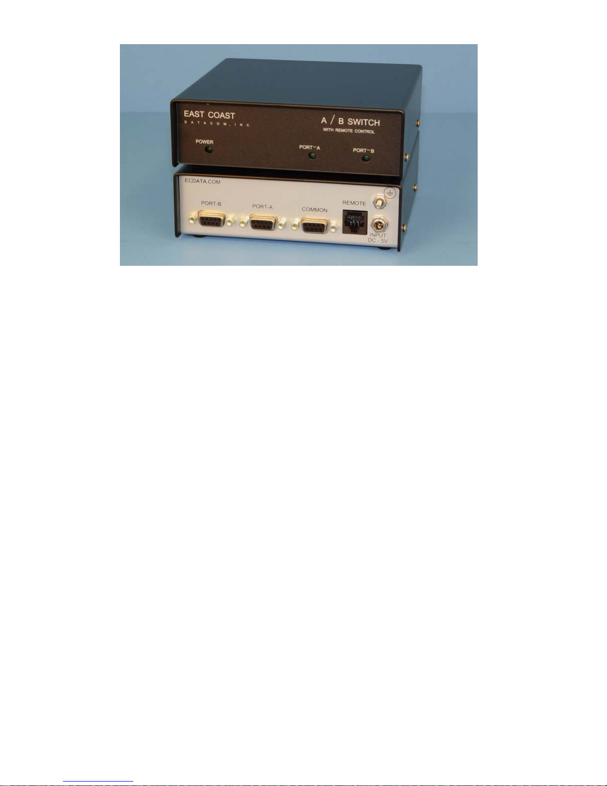
DESCRIPTION
The A/B Switch allows secure and safe switching between computer or data ports. The unit supports switching
4-wires of user data traffic from the Common Port to Ports-A or Port-B. All switching is accomplished with dry
contact positive latching relays for years of dependable service. In the event of local power failure, the A/B
Switch will default to Port A.
The switching between Port A to Port B are accomplished with a remote device that applies a contact closure to
the A/B Switch via the RJ-45 Remote Port. The switching takes place when 4-GND and Pin-6 make or break contact. If power is ever lost to the A/B Switch, the relays with switch to Port-A and continue working without
power.
The front panel has three status LED’s that present the user with Port A or Port B active status. A power LED is
also present to indicate that the A/B Switch has power applied.
The A/B Switch is housed in a sturdy metal enclosure and operates on only a 5V DC power supply. All connections and power are protected from surges via internal transorbs.
The A/B Switch has a three year warranty and a 24 hour turnaround on warranty repairs.
GROUND CONNECTION
The A/B Switch has a #8-32 threaded bolt on the back panel. If your system requires a positive ground to the
A/B Switch chassis, connect a ground wire to the #8-32 bolt provided.
VOLTAGE OPERATION
The A/B Switch is powered from a single 5V DC Power Supply which is wall mount.
ECDATA Transformer PT# 711019
AC Supply Input: 100-240AC
DC Output: 5.0V DC 1.5A 7.5W MAX
POWER CONNECTION
The wall mount transformer has a 2.5mm DC Jack attached to the cord.
Plug the 2.5mm jack into the A/B Switch connector marked: DC INPUT
Now, plug the wall mount transformer into the AC outlet.
EAST COAST DATACOM, INC., 245 Gus Hipp Blvd., STE 3, Rockledge FL 32955
TEL: (321) 637-9922 FAX: (321) 637-9980 www.ecdata.com
A/B Switch, Installation Guide Manual PT# 262008 Rev-
INDICATORS – LED’s
The front panel is marked with a POWER LED and should be illuminated when power is applied to the unit.
Additionally, PORT A and PORT B LED indicators are provided and only one port will illuminate when the
port is selected.
INSTALLING THE A/B SWITCH
The user should plug the data cables into the appropriate ports Marked COMMON, PORT-A and PORT-B.
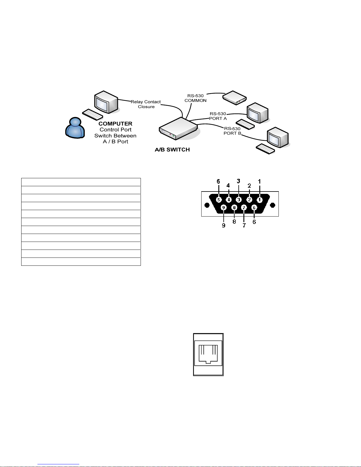
Figure 1
Pin 1 Earth GND
Pin 2 No Connect
Pin 3 No Connect
Pin 4 RXD (A)
Pin 5 RXD (B)
Pin 6 No Connect
Pin 7 Ground
Pin 8 TXD (A)
Pin 9 TXD (B)
Figure 2 - DB9 View looking into female connector
(A) = + lead
(B)= - lead
A/B Leads shown to keep high speed signals in pairs through relays
****All signals are really just wires end to end and can be any signals****
RELAY CONTACT CLOSURE CONNECTOR
The A/B Switch Port A to Port B switching is controlled by the REMOTE port which is RJ-45.
Pins Supported 4-GND and 6-Make Contact from Relay
Pin 1 Open
Pin 2 Open
Pin 3 Open
Pin 4 GND
Pin 5 Open
Pin 6 CONNECT
Pin 7 Open
Pin 8 open
RJ45 View looking into female connector
1-----------8
RJ-45
EAST COAST DATACOM, INC., 245 Gus Hipp Blvd., STE 3, Rockledge FL 32955
TEL: (321) 637-9922 FAX: (321) 637-9980 www.ecdata.com
 Loading...