

East EA900IIRT 1000VA, EA900IIRT 3000VA, EA900IIRT 2000VA, EA900IIRT 1500VA User Manual

- 1 -
MANUAL DE USU A RIO
UPS ON LINE DOBLE CONVERSION
EAST EA900II RT DE 1000 – 3000 VA
- 2 -
Please strictly obey all the instructions in this manual and pay attention to all the warning and operation
information. It is not advisable to install or operate the machine before read this manual.
1. Safety Instructions
● The power outlet voltage may still have 220V even not connect to the mains power.
● For the battery cable or power cord replacement, please contact our service station or dealer to
purchase, in order to avoid fire caused by inadequate capacity or heat ignition.
● Do not place the battery or battery pack in the fire, that will injure due to explosion.
● Please do not open the UPS case as you will, there is risk of electric shock.
● Do not touch the battery connection terminals. Battery loop and input voltage loop is without
isolation, which may cause high voltage risk between the battery terminal and ground.
● Should not connect the equipment like hair dryer or electric heater, to ensure the safety for the UPS.
Attention:
UPS has high voltage inside, for the personal safet y, please do not repair by yourself. If any quest ions,
please contact local service center or dealer.
2. Installation Instructions
2.1. Unpacking Inspection
● Open the UPS package, please check the enclosed accessories including a user manual,
communication cable, support feet, CD-ROM, the cable for connection to battery bank.
● Check the UPS if any damage in transport. If found damaged or parts missing, do not power on,
please turn to the carrier and dealer.
● To determine whether this UPS is the model you want to buy. Check the model name showed both
on the front panel and rear panel of UPS to confirm.
Model
Type
Model
Type
1KVA RTS
1KVA Standard model
1KVA RTH
1KVA Long backup model
1.5KVA RTS
1.5KVA Standard model
1.5KVA RTH
1.5KVA Long backup model
2KVA RTS
2KVA Standard model
2KVA RTH
2KVA Long backup model
3KVA RTS
3KVA Standard model
3KVA RTH
3KVA Long backup model
- 3 -
Note:
Please save the packaging box and packaging materials for future transport use. As heavy product,
please transit the UPS with care.
2.2. Attention items of installation
● The UPS lo cation circumstance must be with good ventilation, awa y from water, flammable gases
and corrosive entities.
● Do not li e down the UPS against the wall so that front and side panel air intake hole, rear p anel air
outtake hole unobstructed.
● The peripheral environment temperature around the UPS should be within 0 ℃ ~ 40 ℃.
● If dismantling the machine at low temperatures, there may be condensation droplets, users can not
install or operate it before completely getting dry both inside and outside, otherwise there will be
danger of electric shock.
● Place the UPS near the mains socket to cut off AC mains without any delay at any emergent case.
Attention:
● Make sure the load after the UPS is off when user start wiring the load t o UPS, then turn on them
one by one later.
● Please connect the UPS with the socket which is over-current protected.
● All the power socket should be configured with earthling devise for safety.
● UPS could be electrified or powered whether the input power cable is tied on or not, even when the
UPS is off. The only way to cut off the output is switching off the ups and disconnecting the
mains power supply first and second.
● For all standard t ype UPS, it is advised to charge the battery over 8 hours before virginally used.
Once the AC mains power energizes the UPS, it will auto-start the charging work. If without prior
charging, UPS output remains as usual but with shorter back up time than normal.
● When connect motor, display equipment, laser printer etc, UPS power selection should be based on
the startup power of the load which is usually twice as rated power.
2.3 UPS and Battery Pack rear panel view
USB
TEL/MODEM/FAX
IN
OUT
-+-
+
24VDC 40A
EXT.BATTERY
RESET
FUSE 250VAC,8A
INPUT
OUTPUT SOCKET
INTELLIGENT SLOT
EPO
RS232
R
E
S
E
T
R
E
S
E
T
T
O
1
2
4
5
6
7
3
8
11
9
10
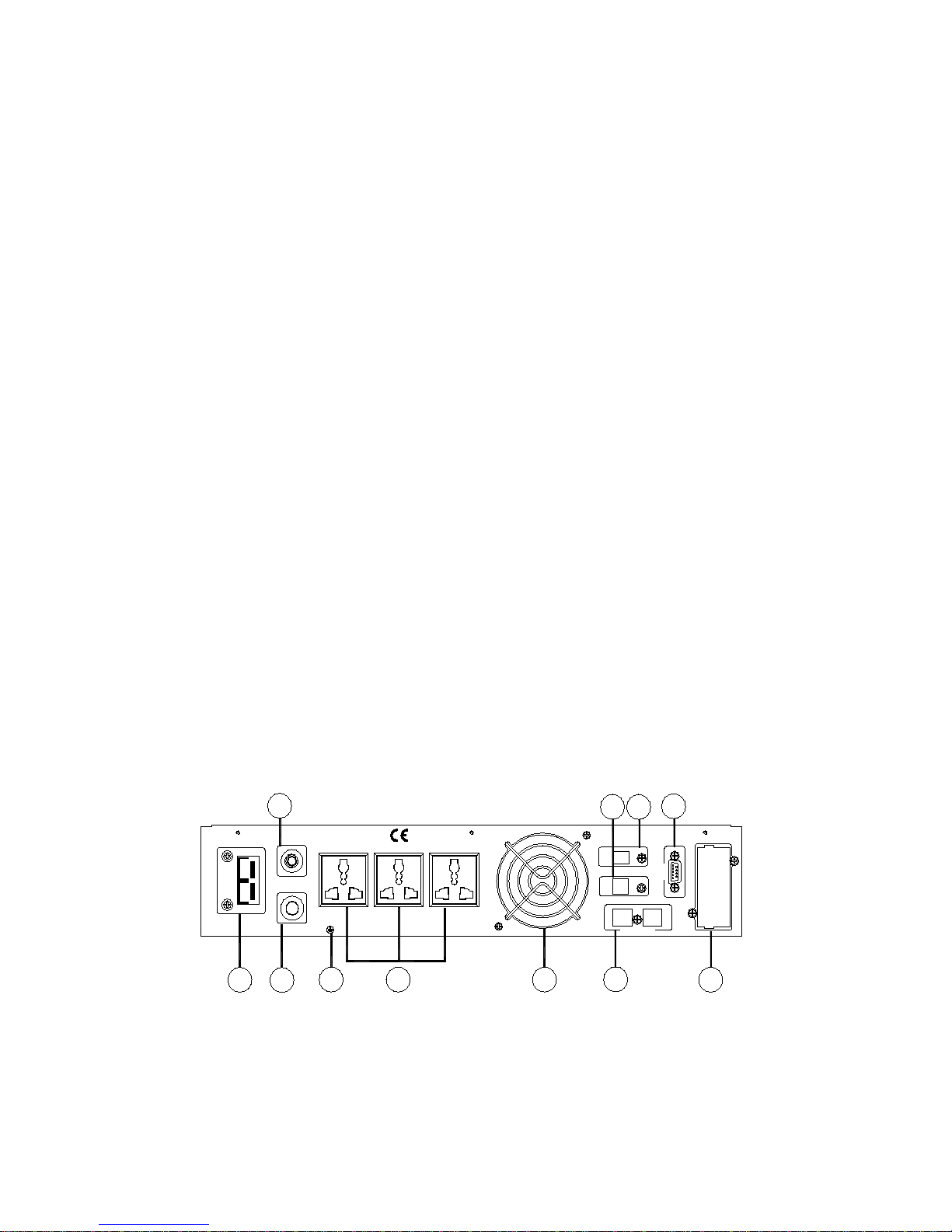
Figure 1. 1KVA rear panel
- 4 -
RESET
FUSE 250VAC,15A
INPUT
OUTPUT SOCKET
EPO
USB
RS232
INTELLIGENT
SLOT
R
E
S
E
T
R
E
S
E
T
T
O
-+-
+
48VDC 40A
EXT.BATTERY
TEL/MODEM/FAX
IN
OUT
1
7
3 2
11
5
10
9
4
6
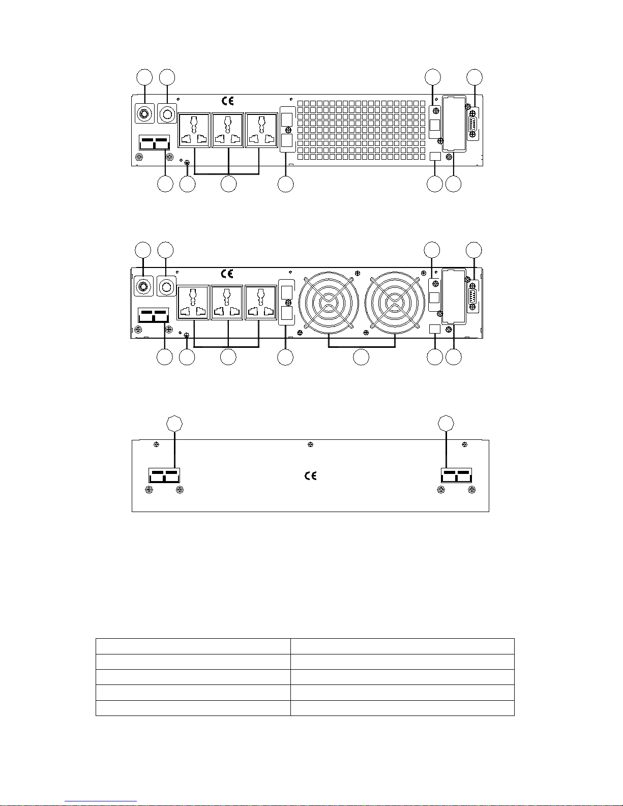
Figure 2. 1.5KVA & 2KVA rear panel
RESET
FUSE 250VAC,20A
INPUT
-+-
+
72VDC 40A
EXT.BATTERY
OUTPUT SOCKET
EPO
USB
TEL/MODEM/FAX
IN
OUT
INTELLIGENT
SLOT
R
E
S
E
T
R
E
S
E
T
T
O
RS232
3 2
10
6
1
7
11
5
9
4
8
Figure 3. 3KVA rear panel
+
-
DC OUTPUT
+ -
DC OUTPUT
72VDC 72VDC
1
1
Figure 4. Battery Pack rear panel
⑴Battery Slot;⑵Input Power Terminals;⑶Over Current Protector;⑷Intelligent Slot;
⑸Surge Protection for Network/Fax/Modem;⑹RS232 Communication Interface;
⑺Output Socket;⑻Fan;⑼Emergency Power Off;⑽USB;⑾Ground.
2.4 UPS output connection
Type
Connectors (The socket type is selectable)
1KVA RTS & 1KVA RTH
Multi-purpose Socket (3)
1.5KVA RTS & 1.5KVA RTH
Multi-purpose Socket (3)
2KVA RTS & 2KVA RTH
Multi-purpose Socket (3)
3KVA RTS & 3KVA RTH
Multi-purpose Socket (3)
Output connection of 1~3KVA type is configured with sockets,end user can plug the load cable on
the UPS socket to energize the load .
- 5 -
2.5 External battery connection procedure for long back up type
● As per different UPS type, end user are instructed to configure different battery voltage as below
sheet. More or less units are forbidden or else something abnormal or faulty will appear.
Type
Battery Quantity (unit)
Battery Voltage (volt)
1KVA
2
24
1.5KVA
4
48
2KVA
4
48
3KVA
6
72
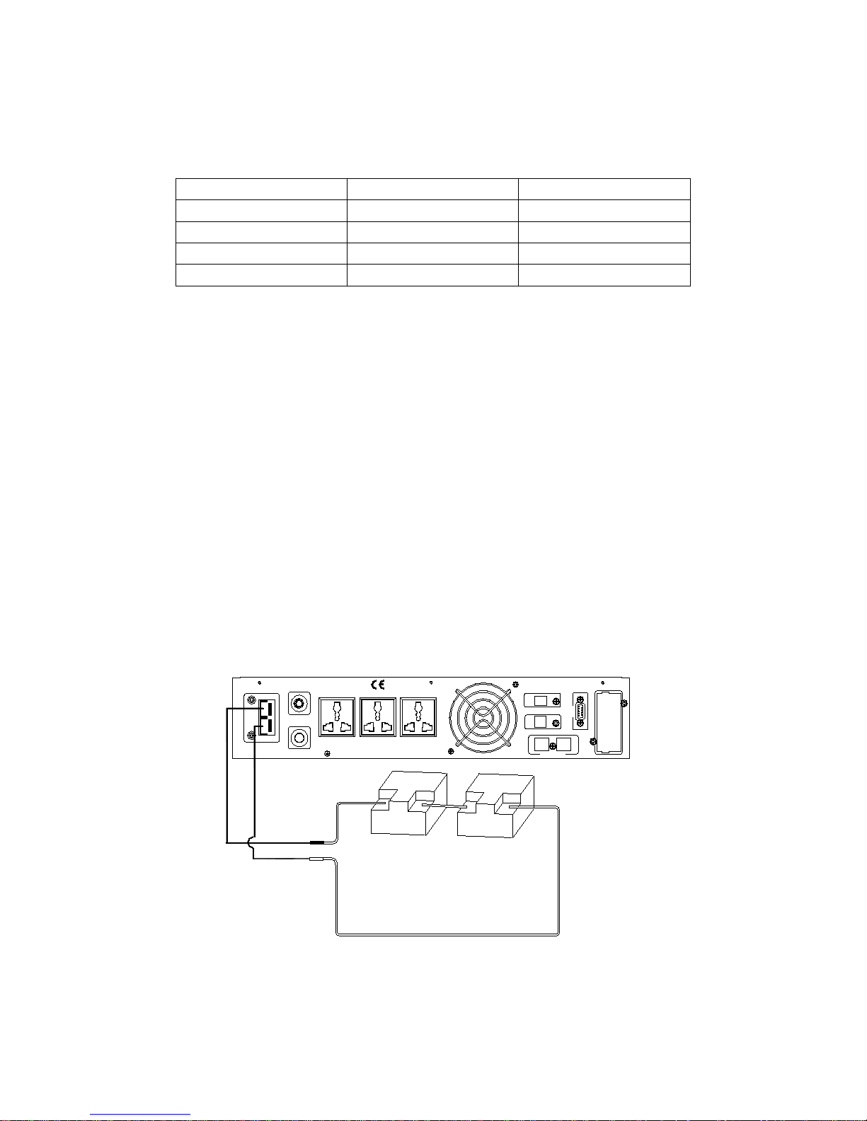
● One end of b attery cable is for UPS terminals while the other end with triple cables is for battery
terminals. Correct installation procedure is highly vital or else probable electric shock will arise.
Users are strictly required to follow the below procedure.
● Connect battery in correct way and make sure the total battery voltage is available for UPS.
● Correctly connect the long battery cable to battery terminals first, red wire is to positive plate while
black is to negative. If users connect the UPS first, electric shock or other danger could not be
avoided.
● Before connect load after UPS, users should supply main power to UPS and energize it.
● Connect long battery cable to UPS terminals with correct poles link (red is for “+”,black is
for“-”), UPS will auto start the charging work.
The connection view is like below figures:
USB
TEL/MODEM/FAX
IN
OUT
-+ -+
24VDC 40A
EXT.BATTERY
RESET
FUSE 250VAC,8A
INPUT
OUTPUT SOCKET
INTELLIGENT SLOT
EPO
RS232
R
E
S
E
T
R
E
S
E
T
T
O
+
-
RED
BLACK
+
-
Figure 5. 1K VA long back up connection

- 6 -
RESET
FUSE 250VAC,15A
INPUT
OUTPUT SOCKET
EPO
USB
RS232
INTELLIGENT
SLOT
R
E
S
E
T
R
E
S
E
T
T
O
-+ -+
48VDC 40A
EXT.BATTERY
TEL/MODEM/FAX
IN
OUT
RED
BLACK
-
+
-
+
-
+
-
+
Figure 6. 1.5KVA &2KVA long back up connection
RESET
FUSE 250VAC,20A
INPUT
-+ -
+
72VDC 40A
EXT.BATTERY
OUTPUT SOCKET
EPO
USB
TEL/MODEM/FAX
IN
OUT
INTELLIGENT
SLOT
R
E
S
E
T
R
E
S
E
T
T
O
RS232
RED
BLACK
-
+
-
+
-
+
-
+
-
+
-
+
Figure 7. 3KVA long back up connection
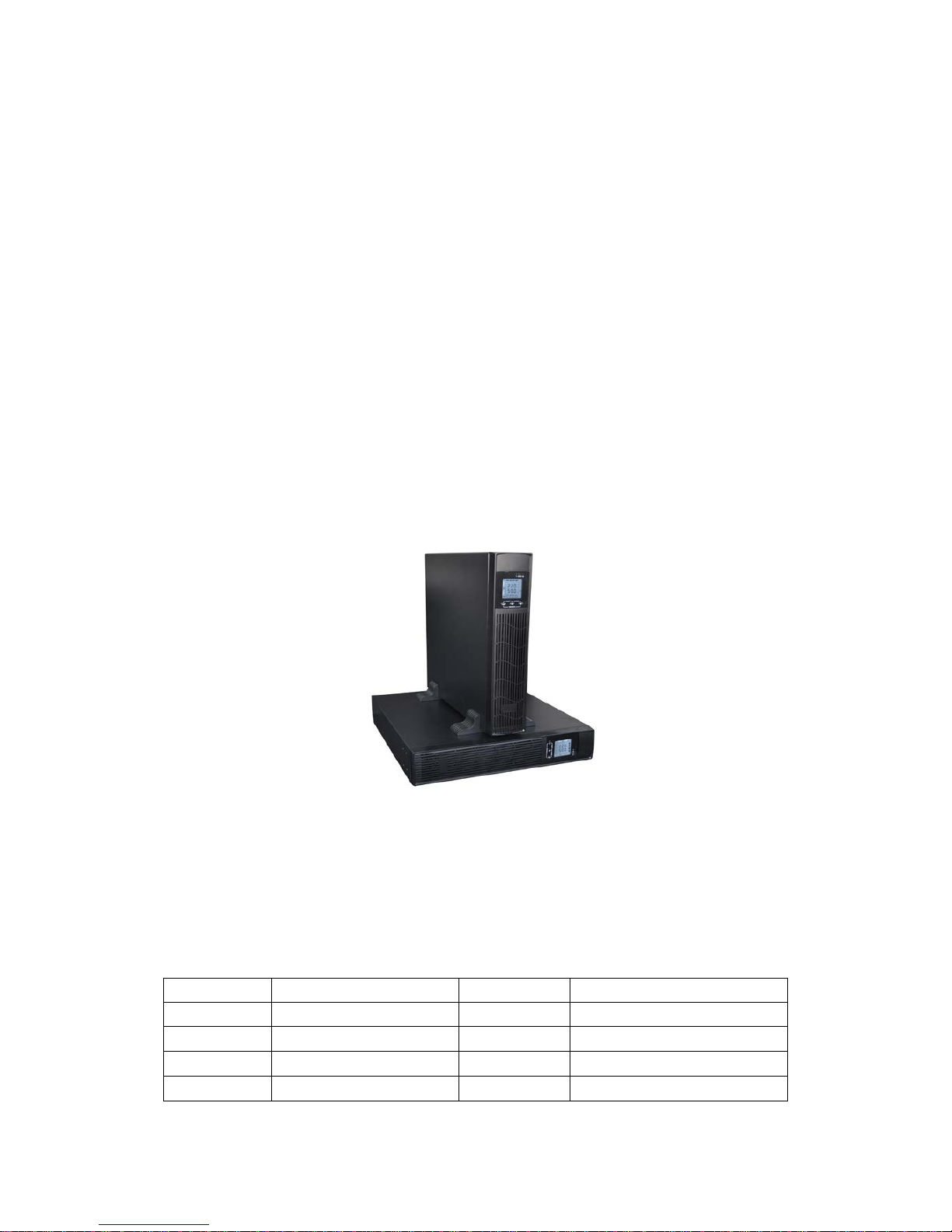
2.6 Installation
● UPS installation work should comply with local electrical standard and only can be done by
professional technician. 1KVA~3KVA units could use wall socket as input power connection.
● For all type UPS, it is advised to charge the battery over 8 hours before virginally used. Once the AC
mains power energizes the UPS, it will auto-start the charging work. If without prior charging, UPS
output remains as usual but with shorter back up time than normal.

- 7 -
Installation steps:
1) Please take out two groups of supports, assemble by embedding them with each other as shown
below.
2) Place the two supports in parallel, then put the machine into two supports.
3) It also can be placed horizontally if you like, please remember not to put the machine upside
down.
4) Machine and battery pack, can be put together, as two ways are showed in the pictures below, the
battery pack should be put under the machine.
3. Panel function and operation
The operation is simple, operators only need to read the manual and follow the operation
instructions listed in this manual without any special training.
- 8 -
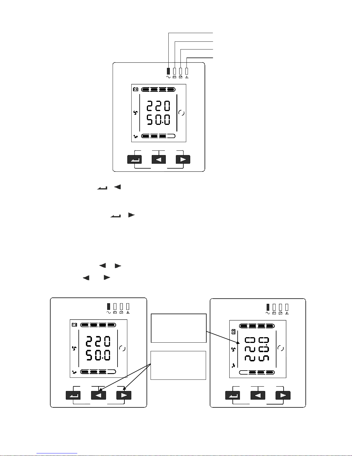
3.1 Keys function
※ ON/OFF key ( + )
Press and hold this key for more than half a second to turn on/off the UPS.
※ TEST/MUTE key ( + )
Press and hold the key for more than 1 second in mains mode or economical mode: UPS runs the
self-test function.
Press and hold the key for more than 1 second in battery mode: UPS runs the mute function.
※ ROTATE key ( + )
Press and hold and for more than half a second (less than 2 seconds): Change the direction to
display items.
ON/OFF
ROTATE
TEST/MUTE
25%
50%
75%
100%
25%
50%
75%
100%
VAC
HZ
LINE
OUTPUT
ON/OFF
ROTATE
TEST/MUTE
25%
50%
75%
100%
25%
50%
75%
100%
OUTPUT
LINE
VAC
HZ
ON/OFF
ROTATE
TEST/MUTE
25%
50%
75%
100%
25%
50%
75%
100%
VAC
HZ
LINE
OUTPUT
Press and hold
keys for more than
half a second.
The direction has
been changed in
the picture.
Inverter LED
Battery LED
Bypass LED
Warning LED
 Loading...