

East EA610, EA615, EA620, EA630 User Manual

-2-
1. Safety and Overview
Safety precautions (In order to ensure the safety, please observe the following)
Please be sure to read the user’s manual before use.
Please charge the product for more than 8 hours before using it.
When the battery has been discharged or the storage period has been more than 3
months, the battery shall be charged for more than 8 hours in time, so as to ensure it
is fully-charged and prevent it from being damaged.
This product is specially designed for group computers. It shall not be connected with
inductive loads (e.g. motor, refrigerator, etc.). It is not recommended for life
supporting system and other specific major equipments.
When installing the product, please maintain a distance of more than 50cm away
from the display.
The normal temperature of the chassis surface will reach about 50℃ during the use
of this product, which is a normal phenomenon.
Do not use UPS which goes beyond the rated load capacity.
Do not open UPS case, or it will lead to electric shock or other dangers. If it is
required to conduct an internal overhaul or replace the battery, please deliver it to the
designated maintenance center.
As internal short-circuit will result in electric shock or f ire, any vessel containing
liquids shall not be placed on UPS for fear of electric shock or other dangers.
When the machine works abnormally, cut off the power immediately, and contact the
supplier.
Never store or use this product in the following conditions.
1) The place where there is no air convection
2) The place where combustible gas, corrosive substance or a great deal of dust
exists
3) The place where the temperature is extremely high or low (above 40℃ or below
0℃) and the humidity is high (above 90%)
4) The place having direct sun exposure or close to heating equipment
5) The place where violent vibration occurs
6) Outdoor
-3-
In case of fire around UPS, put out the fire with powder fire extinguishers. Using fluid
extinguisher may lead to electric shock.
Please place the power socket near UPS, so that UPS can be disconnected from the
socket in emergency.
When it is required to move or re-connect UPS, the AC input power shall be cut off to
ensure UPS stops completely, or the output end may be live which may result in
electric shock.
The battery life is shortened as the ambient temperature rises. Periodic battery
replacement can ensure UPS works properly and there is enough backup time.
The battery maintenance shall only be carried out by the personnel having
professional knowledge of batteries.
Since the dangers of electric shock and short-circuit current exist, the following
warnings shall be observed in battery replacement to avoid electric shock.
1) Do not wear watches, rings or other metal objects.
2) Use insulated tools.
3) Wear rubber shoes and glove.
4) Do not place metal tools or metal parts on the battery.
5) First disconnect the load connected to the battery before removing connecting
terminals of the battery.
6) Do not short-circuit the positive and negative terminals, or it will lead to electric
shock or fire.
7) Do not touch the connecting terminal of the battery. Do not separate the battery
circuit from the input voltage circuit. The danger of high voltage exists between
the battery terminal and ground.
Warning!
The equipment must be grounded. When AC utility power is
connected, the system shall be grounded reliably.
Improper operation will result in huge losses. Please be sure to
operate this product according to the requirements of operation
instructions.
-4-
2 Installation Instructions
2.1 Unpacking and checking
2.1.1 Unpack UPS, and check accessories
Host
Instructions
Warranty card
Communication line
Power cord
CD
Battery connecting wire (not provided for standard UPS)
Accessories of fixed support (not provided for tower UPS)
Rack (wall-mounted) accessories (not provided for tower UPS)
Others according to requirements of the contract
Note: Please keep the carton and packaging materials of the machine for convenience of
future handling. The series of products are very heavy which shall be handled with care.
2.1.2 Check whether UPS is damaged during the transportation. If any
damage or missing parts are found, do not start up the machine, and inform
the carrier and distributor
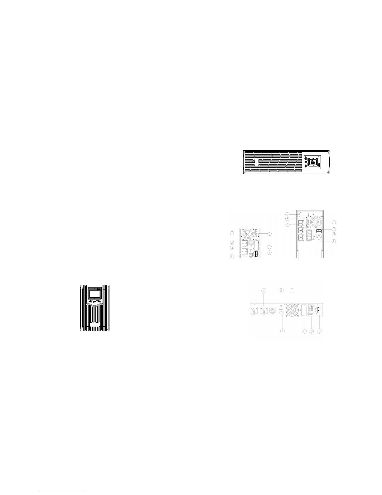
2.2 UPS front panel view
TEST/MUTE
ON OFF
Fig. 2.2 Tower panel
-5-
ROTATE/SET
TEST/MUTE
VAC
HZ
OUTPUT
25%50 % 75% 1 00%
25% 50%
75%
100%
LINE
ON OFF
Fig. 2.2 Rack panel
2.3 UPS rear panel view
2.3.1 Tower rear panel
Fig. 2.3.1 1KVA-2KVA rear panel (left), 3KVA rear panel (right)
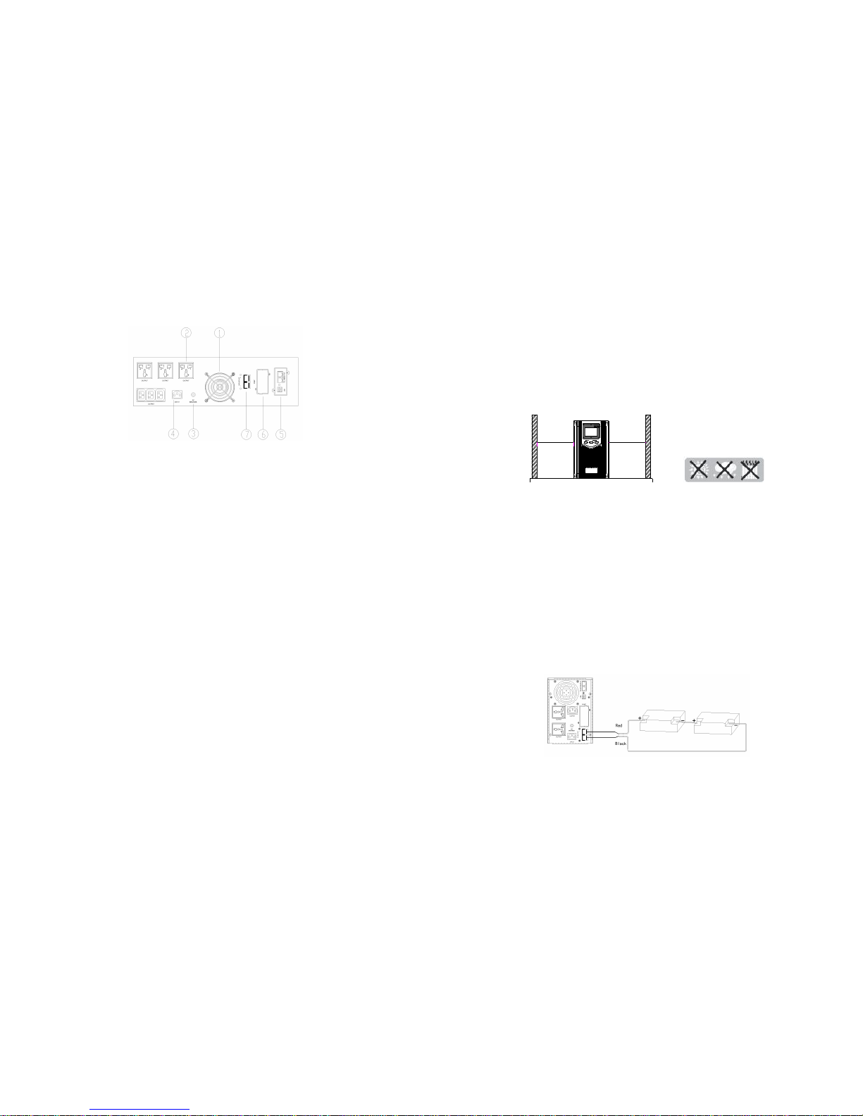
2.3.2 Rack rear panel
Fig. 2.3.2 2U 1KVA rack rear panel
-6-
Fig. 2.3.2 3U 1.5KVA-3KVA rack rear panel
Description of rear panel
a) Fan and fan guard
b) Output power supply socket
c) AC over-current protector
d) IEC Input socket
e) Communication interface (standard configuration USB+RJ45)
f) SNMP card slot
g) External battery connector
2.4 Product installation instructions
2.4.1 Installation attentions
1. Put UPS in a well-ventilated place and ensure the heat emission holes and fan
peripherals of the chassis meet the ventilation conditions at a distance of
150mm above and keep away from water, combustible gases and corrosives.
2. Turn off the devices which need uninterrupted power supply (such as host
computer), disconnect the power cord from the utility power socket and connect
it to the output s ocket of UPS connect the devices which do not need to be
connected with UPS to the common utility power socket.
3. Put UPS input plug into the utility power socket (ensure the zero wire and live
wire are correct and the ground wire is good).
4. The ambient temperature of UPS shall be kept between 0℃ and 40℃.
-7-
5. It is recommended to charge the battery for 8 hours before using it. UPS will
charge the battery automatically as long as the input utility power meeting
requirements is connected to the host.
6. For the extended runtime model, connect the battery first after confirming the
battery wires, and then connect the utility power line.
15cm
OFFON
TEST/MUTE
15cm
Fig. 2.4.1 Installation attentions
2.4.2 Battery installation attentions for extended runtime model
Warning:
In order to ensure the safety of equipment and personnel, theinstallation must be
carried out by professionals.
1. First connect the battery bank with accompanied battery connecting wires (note
the red wire shall be connected to the anode, and the black wire shall be
connected to the cathode).
2. Confirm the connection of the battery bank. Measure the identification of the
battery input socket and the positive and negative of battery wire terminals of
UPS with a multimeter. The voltage shall be consistent with UPS’s input DC
voltage.
3. Be sure to check whether the installation is correct or not after it is completed.
Fig. 2.4.2 Schematic diagram of DC24V tower battery connection
 Loading...