

EA Sports PGA TOUR GOLF Instructions Manual
Tournament Play Hardware Kit Instructions for
®
EA SPORTS™ PGA TOUR
GOLF Conversion Cabinets
Document Part Number: 040-0054-01 Rev. A
This document describes the steps for installing the tournament hardware for an EA SPORTS™
PGA TOUR® GOLF Conversion Cabinet. Hardware installation consists of the following steps:
• Convert the Tournament Header (Important: The Tournament Header Controller
Board is required for the system to run tournaments. If you do not have an existing
tournament header, you must still connect the board. See Header Controller Board
Installation for Systems with no Tournament Header on page 2.)
• Install the Card Reader
• Install the Telephone Cable
Once all hardware is installed, you will be ready to register your cabinet for tournament play.
For complete registration information, refer to the Tournament Operator Guide or Online
Tournament Quick-Start Guide for Operators.
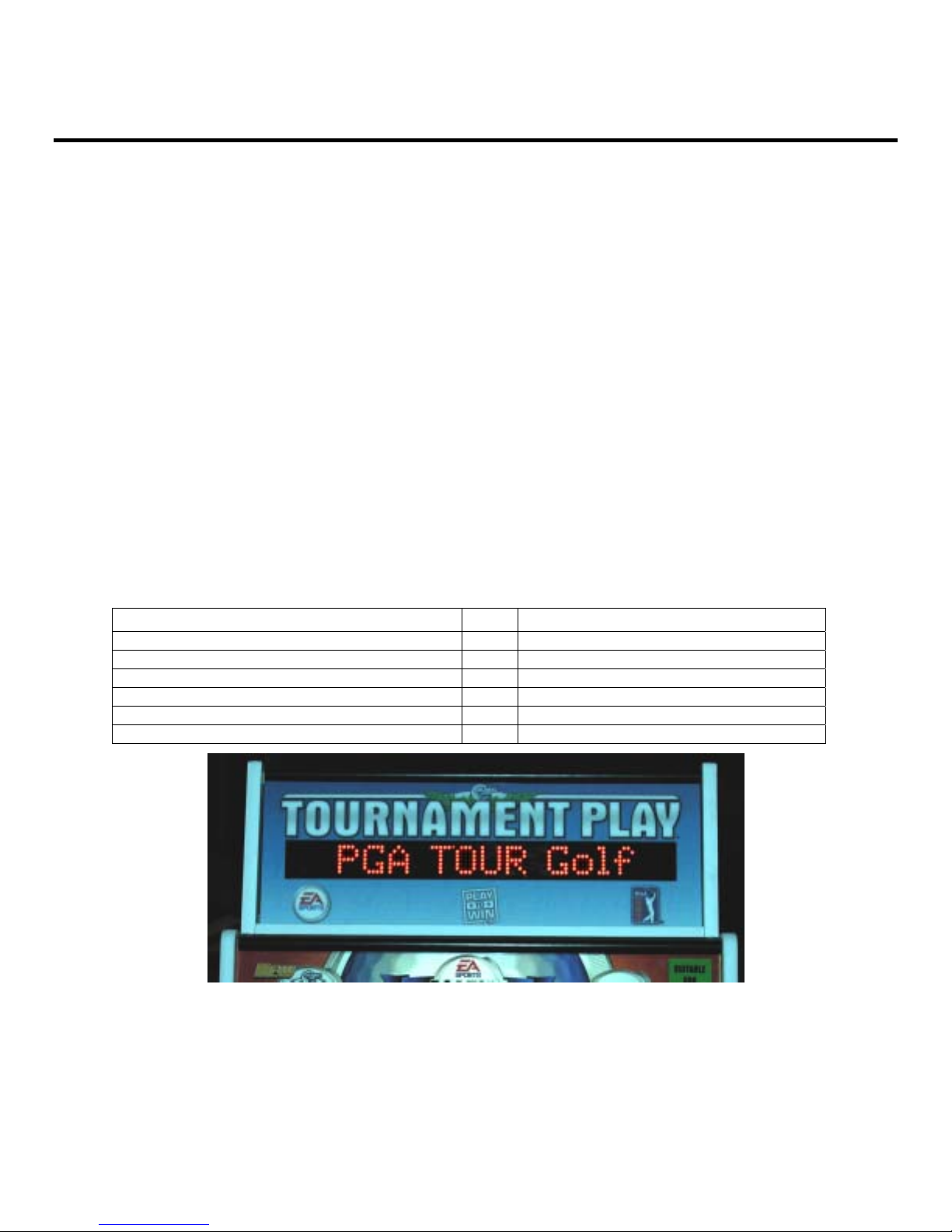
Tournament Header Conversion
Perform the steps in this section to convert an old tournament header for use with your converted
EA SPORTS™ PGA TOUR® GOLF cabinet. If you prefer to install a standard GLOBAL VR®
tournament header, contact GLOBAL VR® for ordering information.
The Tournament Header Upgrade Kit contains the following components:
Description Qty Part Number
Header Controller Board 1 990-0010-01
Control Harness 1 GLO-D9-R6
Power Harness 1 V2-420035-00
Artwork 1 PGAK-AW-24
Mounting Plate 1 37052-00
Nylon Screws, 6-32 x 1/4" 4 4600-0030
Figure 1. Tournament Header After Upgrade
1. Remove the screws from the top of the tournament header and remove the clear plastic that
holds the header artwork in place. Slide the artwork out from in front of the LED board.
Clean the clear plastic.
2. Install the new artwork and replace the clear plastic and screws.
©2004 GLOBAL VR, Inc. All rights reserved. GLOBAL VR and the GLOBAL VR logo are registered trademarks of GLOBAL VR, Inc. All other trademarks
are the property of their respective owners. Electronic Arts, EA SPORTS, and the EA SPORTS logo are
Electronic Arts Inc. in the U.S. and/or other countries. All rights reserved. EA SPORTS™ is an Electronic Arts™ brand. PGA TOUR, and PGA TOUR and
Swinging Golfer Design are trademarks of PGA TOUR, INC. and used by permission.
trademarks or registered trademarks of

3. Remove the screws that secure the back cover to the tournament header and carefully lift the
back cover to access the 16-pin controller board connector.
4. Disconnect the 16-pin connector from the controller board that is mounted to the back cover.
5. Disconnect the cables from the controller board and remove them from the cabinet.
6. Take the back cover to a convenient work surface and remove the four nuts and washers that
secure the controller board in place. Remove the controller board.
7. Remove the four (4) nylon spacers from the controller board and install them on the four
bolts on the tournament header back cover.
8. Install the mounting plate on top of the nylon spacers on the tournament header back cover
so that the four threaded standoffs are on the left side. Secure the plate with four kep nuts.
9. If the new header controller board was not pre-installed on the metal mounting plate, install it
on the four standoffs so that the connector is at the far left side. Secure it with nylon screws.
10. Make sure that no metal pieces, such as the mounting plate or kep nuts, touch the edge
connector of the board.
Figure 2. Mounting the Controller Board
11. Connect the DC power harness from the kit to an available PC power connector in the
cabinet and route it through the hole in the bottom of the header.
12. Connect the control harness to COM1 on the computer and route it through the hole in the
bottom of the header. (Refer to Figure 3 on page 8 for computer connections.)
13. Connect the power harness to the power port, J2 on the controller board.
14. Connect the control harness to J3 on the controller board.
15. Connect the 16-pin connector from the LED board to the controller board.
16. Replace the back cover on the tournament header and secure it with the screws removed in
step 3.
17. Power on the system and verify that the tournament header works properly.
Header Controller Board Installation for Systems with no Tournament Header
The computer must detect the Header Controller Board or tournaments will not be activated.
This section describes how to install the board if your cabinet does not have an existing
tournament header.
1. If the controller board was not pre-installed on the metal mounting plate, place it on the four
standoffs and secure it with nylon screws.
Tournament Play Hardware Kit Instructions for Golf Conversion Cabinets
Page 2 of 8
© 2004 GLOBAL VR, INC. 040-0054-01 Rev. A 11/4/2004
2. Mount the controller board mounting plate to the cabinet with three #6x1/2" wood screws.
3. Connect the DC power harness from the kit to an available PC power connector and J2 on
the header controller board.
4. Connect the control harness to COM1 on the computer and J3 on the controller board.
(Refer to Figure 3 on page 8 for computer connections.)
5. Power on the system and verify that the LED on the controller board lights, and tournaments
are available from the Operator Menu.
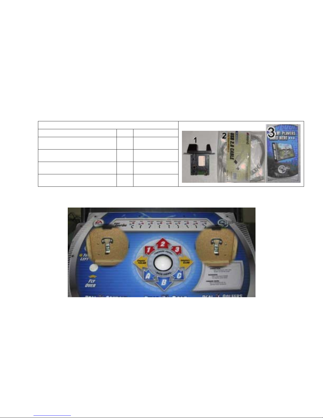
USB Card Reader Installation
Perform the steps in this section to install the USB card reader.
USB Card Reader Components
Description Qty Part Number
Card Reader
Card Reader Mounting Plate 1
USB to Card Reader Cable
Card Reader Graphics
1
1
1
7101USB
PGA-6016-00
USB-AB06MM
PGA-AW-05
1. Reach in through the coin door and unlatch the control panel from underneath, as shown in
the picture below.
Tournament Play Hardware Kit Instructions for Golf Conversion Cabinets
Page 3 of 8
© 2004 GLOBAL VR, INC. 040-0054-01 Rev. A 11/4/2004
 Loading...