

Page 1
SUBZERO-10
1500 WATTS
Winner of the 2004
Design & Engineering Award
INNOVATIONS
INTERNATIONAL CES
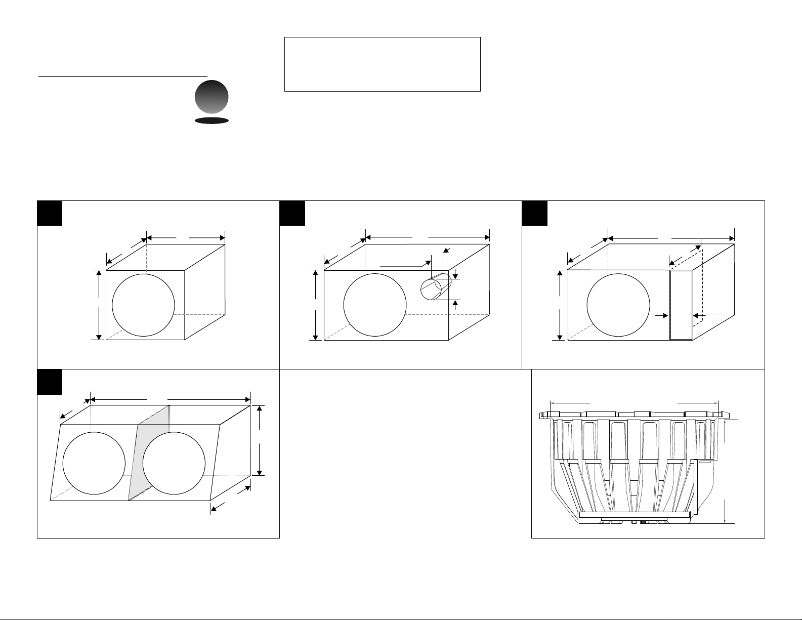
1” = 2.54 cm
1 cubic foot = 1728 cubic inches
Grille Clearance: 2”
Displacement:
Sealed design for tight bass
#1
11"
12"
SUBZERO-10"
Outer dimension shown using 3/4" thick MDF
Total outer box volume = 0.91 cubic foot.
Sealed design for tight bass
#1
15”
SUBZERO-10" SUBZERO-10"
23 1/2”
12"
18 1/2”
12”
Port tuned design for deep bass
#2
16"
11”
12"
Outer dimension shown using 3/4" thick MDF.
Total outer box volume = 1.22 cubic feet.
SUBZERO-10"
#2
8 1/2" long
Port
4"
diameter
#3
Ported design
15"
15 1/2"
12"
Outer dimension shown using 3/4" thick MDF
Total outer box volume = 1.61 cubic feet.
SUBZERO-10"
11"
Internal dimensions
PORT (2"x10.5"x11")
SUBZERO-10
Cut out hole 235mm / 9 1/4”
Mounting
depth
220mm
6 1/2”
Outer dimension shown using 3/4" thick MDF
Total outer box volume = 2.73 / 1.36 per sub
Specifications are subject to change without notice
HANDCRAFTED IN USA.
Page 2
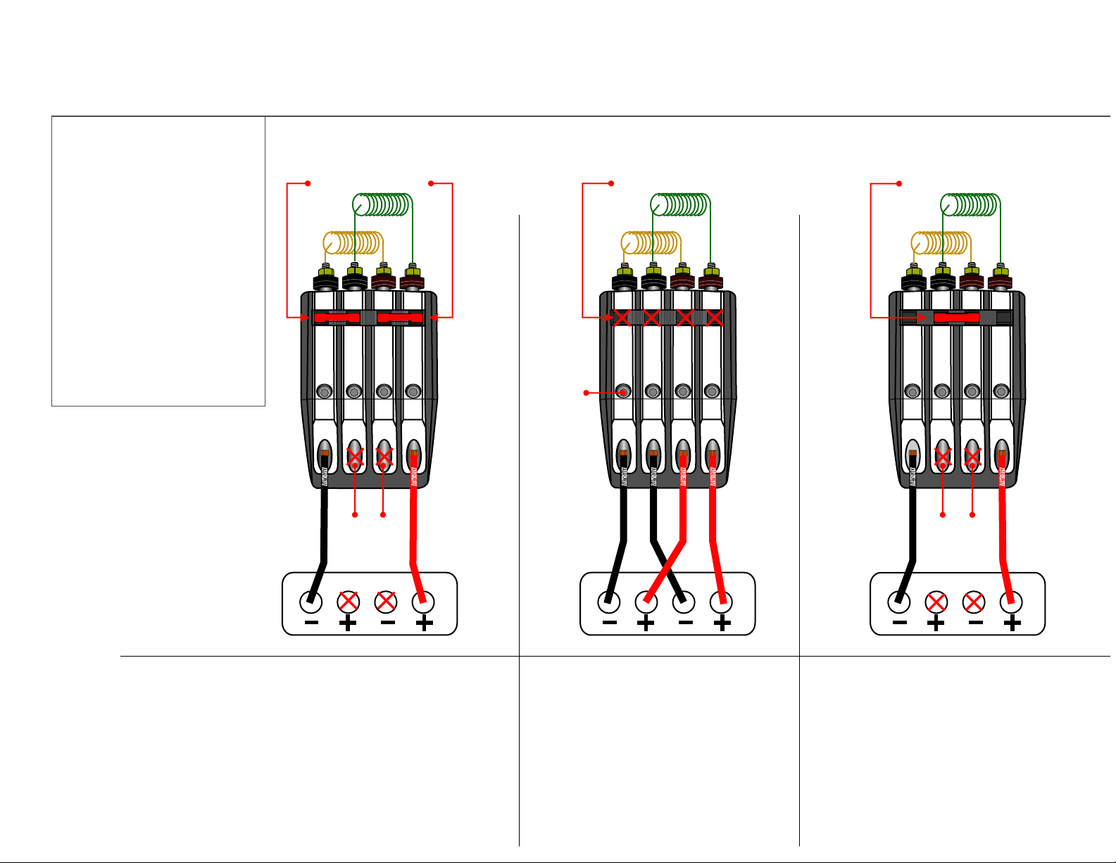
HOW TO WIRE / FUSE YOUR
SUBZERO TO AN AMPLIFIER
The Subzero subwoofer
comes equipped with 2
voice coils (dual 2x4
ohms), it can be used in
2 , 4 a n d 8 o h m
configurations. The
terminal comes equipped
with fused jumpers, the
voice coil can be easily
configured in series or in
parallel to match the
amplifier in use. It is just a
simple flip of a fuse,
here’s how it works.
VC #1
2-channel
2-ohm load
(voice coils in parallel)
(using 2 fuses)
VC #2
S
- --
1
+ +
2
1
PSP (Parallel Series Parallel) Terminal
2-channel
2 x 4-ohm load
(voice coils separated)
(no fuses)
VC #2
VC #1
PP
PP
S
3mm
Hex-nut
cable
2
fasteners
- --
1
+ +
2
2
1
1-channel
8-ohm load
(voice coils in series)
(1 fuse)
VC #2
VC #1
PP
S
- --
1
+ +
2
1
2
DO NOT
8-GAUGE
USE
MONO 2-OHMS
TYPICAL AMPLIFIER TERMINAL
The diagram -on the left side- shows
the PSP terminal in a 2-ohm parallel
configuration (both voice coils are
connected in parallel). Simply place
the 2 fuses in the outer positions in
the fuse placement area. Insert the
negative speaker wire to the far left
insert and one positive to the far right
insert.
8-GAUGE
8-GAUGE
8-GAUGE
CH-1
TYPICAL AMPLIFIER TERMINAL
This diagram shows the PSP terminal
in a 4-ohm configuration (the two
voice coils are separated). No fuses
are used in this configuration,the voice
coils are powered up separately.
8-GAUGE
CH-2
8-GAUGE
DO NOT
8-GAUGE
USE
MONO 8-OHMS
TYPICAL AMPLIFIER TERMINAL
The diagram - on the right side-displays
the PSP in an 8-ohm mode. You will
notice that there is only one fuse in
the center of the fuse placement area.
The voice coils are wired in series.
Insert the negative speaker wire to the
far left insert and one positive to the
far right insert.
8-GAUGE
Page 3

Electro Mechanical Parameters
Name = Subzero 10 (broken in) Xmax = 31.7500E-3M
Note = VI MEASURMENTS Krm = 52.9380E-3 Ohm
Model = TSL Erm = 667.0000E-3
Domain = FreeAir Kxm =78.4200E-3 H
Shape = Round Exm = 685.0000E-3
Profile = Cone Rms =19.3984 N·S/M
Fmd = 3.0000 KA Mms = 155.7620 g
Qmd = 1.0000 Cms =197.1628 uM/N
Flp = 8.0000 KA Vas = 1.0830 Ft³
Qlp = 2.0000 Fo = 28.7195 Hz
Znom = 8.0000 Ohm Qms = 1.4489
Revc = 7.7000 Ohm Qes = 0.6994
Sd = 33.0000 msqM Qts = 0.4717
Mmd = 152.3169 g BL = 17.5913 T·M
Pmax = 1.0000E3 W Levc = 4.9888 mH
Rtvc =250.0000E-3 °C/W SPLo = 82 dB
Xgap = 500.0000E-3 In No = 0.0995821%
Xcoil = 3.0000 In
 Loading...