

MARINEMARINE
The Sound That Will Move You.
EARTHQUAKE MARINE SPEAKERS
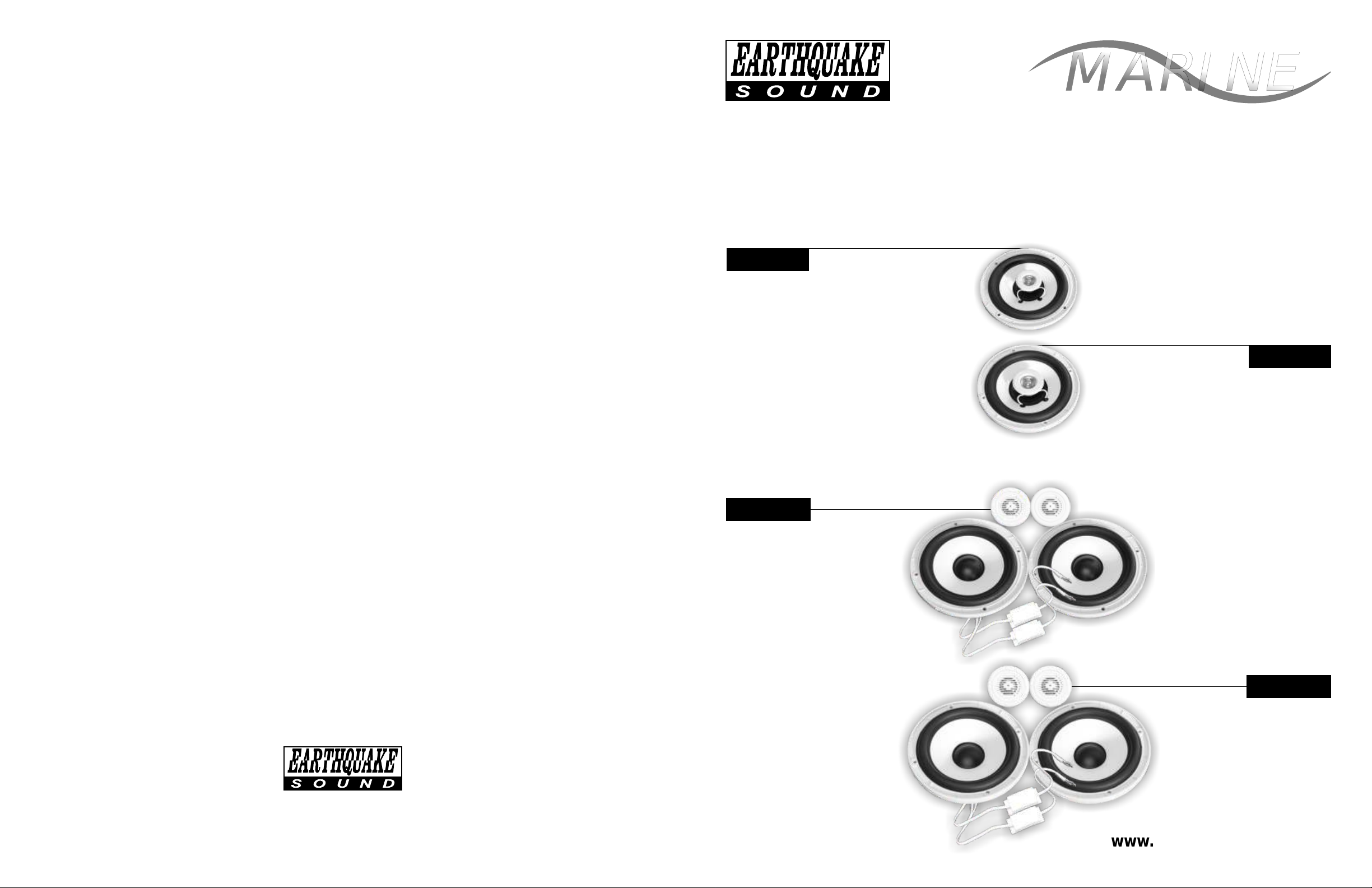
M5
2-WAY 5” COAXIAL SPEAKER
Owner’s Manual & Warranty
M6
2-WAY 6” COAXIAL SPEAKER
The Sound That Will Move You.
Earthquake Sound reserves the right to amend details of the specifications without notice.
Copyright © Earthquake Sound Corporation
Earthquake Sound Corporation • 2727 McCone Avenue Hayward CA, 94545 • Phone: 510-732-1000 Fax: 510-732-1095
MC5
5” MATCHED COMPONENT SET
MC6
6” MATCHED COMPONENT SET
www.earthquakesound.com

MARINEMARINE
High-Performance, Protection and Sound Quality
Table of Content
Page# ……Warranty guidelines
3
Five (5) year limited warranty:
Earthquake warrants the original purchaser that all Factory Sealed New Audio Products be free from defects in
material and workmanship under normal and proper use for a period of five (5) years from the date of purchase (as shown on
the original bill of sale with serial number affixed/written on it). The five (5) year warranty period is valid only if an authorized
Earthquake dealer properly installs the product and the warranty registration card is properly filled out and sent to Earthquake
Sound Corporation. If a non-authorized party installs the product a ninety (90) day warranty period will be applied.
(A) Five (5) years limited warranty plan coverage guidelines:
• First year: Earthquake pays for labor, parts, and return ground freight (only in US mainland, not including Alaska and
Hawaii).
• Second year: Earthquake pays for labor and parts only, customer must pay freight both ways.
• Third, fourth & fifth year: Earthquake pays for labor only. Customer must pay for parts and freight both ways.
(B) Warning:
Products (sent for repair) that are tested by Earthquake technicians and deemed to have no problem(s) will not be
covered by the five (5) year limited warranty. Customer will be charged a minimum of one (1) hour of labor (ongoing rates)
plus shipping charges back to customer.
Page# 4……Components set dimensions
Page# 5……Coaxial dimensions / Coaxial and component specs
Page# 6 & 7……Instalation
Thank you for choosing Earthquake Sound’s line of Earthquake Marine coaxial and component sets for superior
enhancement of your water craft audio system. With proper installation and responsible listening, your marine speakers will
give you years of near perfect sound reproduction.
We strongly recommend you to have your new marine speakers installed by an authorized Earthquake Sound dealer:
Installation professionals employed by your dealer have the correct tools and knowledge to install your speakers neatly and
successfully. Also, when your new products are installed by an authorized dealer, your product will include a FIVE YEAR
LIMITED WARRANTY. If you choose to perform your own installation, your warranty will be subject to limitations. Dealer
policies on handling warranty requests may vary from one dealer to the next. Please read the warranty information in its
entirety and use good judgment when making these vital decisions.
(C) Earthquake will repair or replace - at our option - all defective products/parts subject to the following
provisions:
• Defective products/parts have not been altered or repaired by other than an Earthquake factory approved technician.
• Products/parts are not subjected to negligence, misuse, improper use, or accident, damaged by improper line voltage,
used with incompatible products, or have its serial number or any part of it altered, defaced or removed, or have been
used in any way that is contrary to Earthquake's written instructions.
(D) Warranty Limitations:
Warranty does not cover products that have been modified or abused. Including but not limited to the following:
• Damages to speaker cabinet and cabinet finish due to misuse, abuse, or use of improper use of cleaning
materials/methods.
• Bent speaker frame, broken speaker connectors, holes in speaker cone, surround & dust cap, burnt speaker voice coil.
• Fading, deterioration of speaker components & finish due to improper exposure to elements.
• Bent amplifier casing, damaged finish on the casing due to abuse, misuse, or improper use of cleaning material.
• Burnt traces on PCB.
• Product/part damaged due to poor packaging or abusive shipping conditions.
• Subsequent damage to other products.
warranty claim will not be valid if the warranty registration card is not properly filled out & returned to
Earthquake with a copy of the sales invoice.
A
(E) Service Request:
To receive product/s service, contact Earthquake's service department at (510) 732-1000 and request an RMA
number (Return Material Authorization); items shipped without a valid RMA number will be refused. Make sure you provide us
with your complete/correct shipping address, a valid phone number, and a brief description of the problem you are
experiencing with the product. In most cases, our technicians might be able to resolve the problem over the phone, thus
eliminating the need to ship the product.
(F) Shipping Instructions:
Product/s must be packaged in its original protective box(s) to minimize transport damage. Shipping claims
regarding items damaged in transit must be presented to carrier. Earthquake Sound Corporation reserves the right to refuse
any products improperly packed. Original bill of sale must accompany product returned for service. We encourage you to
include with the package a written description of the problem. Ship product to: Earthquake Sound Corp. 2727 Mc Cone
Avenue, Hayward, CA 94545. Ph (510) 732-1000. You are responsible for the cost of shipping the product to Earthquake
Sound Corporation.
(G) Disputes Resolution:
All disputes - between clients and Earthquake Sound Corporation - resulting from the five (5) years limited
Please keep this warranty information in your files for
future reference if necessary. It is recommended that
you stick your serial number here for future reference.
2
SERIAL NUMBER
EARTHQUAKE SOUND
warranty policy must be resolved according to the laws & regulations of the county of Alameda -California.
EARTHQUAKE SOUND • 5-YEAR WARRANTY 3

MC Crossover Dimensions
M5 COAXIAL DIMENSIONS
Ba
This diagram displays only the crossover.
A
C
B
Mounting components vary in size.
Height
Width a
Width
Depth
A
B
B
D
.97" • 24.7mm
1.64" • 41.8mm
2.08" • 53mm
.94" • 24mm
D
E
A
B
C
A
Grille tray outer
diameter
B
Grille protrusion
C
Mounting depth
D
Magnet width
E
Cut out hole
165.5mm • 6.51”
21mm • .82”
62mm • 2.44”
87mm • 3.42”
130.0mm • 5.11”
MC, Tweeter Dimensions
C
D
B
A
This diagram displays only the raw tweeter.
Mounting components vary in size.
Trim Ring Diameter
Cut Out Hole Diameter
A
Total Depth
C
Mounting Depth
A
B
D
2.15", 54.7mm
1.79”, 45.6mm
.925", 23.5mm
.71”, 18.2tmm
D
E
A
M6 COAXIAL DIMENSIONS
B
C
A
Grille tray outer
diameter
B
Grille protrusion
C
Mounting depth
D
Magnet width
E
Cut out hole
190.2mm • 7.48 ”
26mm • 1.02”
59mm • 2.32”
90mm • 3.54”
147mm • 5.78”
MC5 WOOFER DIMENSIONS
A
B
C
D
Da
E
A
MC6 WOOFER DIMENSIONS
B
C
D
Da
E
A
Grille tray outer
diameter
B
Grille protrusion
C
Mounting depth
D
Magnet width
D
a Magnet width
+ crossover
E
Cut out hole
A
Grille tray outer
diameter
B
Grille protrusion
C
Mounting depth
D
Magnet width
D
a Magnet width
+ crossover
E
Cut out hole
166.5mm • 6.55”
20mm • .78”
61mm • 2.40”
87mm • 3.42”
+ 20mm • .78” for x-over
129.0mm • 5.07”
190.5mm • 7.5”
29.5mm • 1.16”
59mm • 2.32”
90mm •3.54 ”
+ 20mm • .78” for x-over
147mm • 5.78”
MARINE MATCHED COMPONENT SPECIFICATIONS
Model
Woofer
Tweeter
Crossover Networks
Frequency Response
Rec. Amp power
Sensitivity
Nominal Impedance
• 5” UV treated
• 25mm (over 1”) ASV voice coil
• Butyl rubber surround
• PEI dome20mm • .78"
• 2-way network
• Completely sealed
50Hz-22kHz 45Hz-22kHz
75 watts RMS 145 watts max •
89 dB @ 1W/1M 89 dB @ 1W/1M
4 ohm 4 ohm
MC5 (2-way)
poly injection cone body
MARINE COAXIAL SPECIFICATIONS
Model
Woofer
Tweeter
Rec. Amp power
Frequency Response
Sensitivity
Nominal Impedance
UV treated
• 5” poly injection cone body
• Sealed motor structure
• 25mm (over 1”) VC
• Butyl rubber surround
• mylar dome20mm • .78"
50-130 Watts RMS
65Hz - 20kHz (±3dB)
89 dB @ 1W/1M
4 ohm
M5 (2-way)
MC6 (2-way)
• 6.5
” UV treated poly injection cone body
• 30mm (almost 1.25”) ASV voice coil
• Butyl rubber surround
• PEI dome20mm • .78"
• 2-way network
• Completely sealed
85 watts RMS 165 watts max •
M6 (2-way)
• 6” UV treated poly injection cone body
• Sealed motor structure
• 25mm (over 1”) VC
• Butyl rubber surround
• 20mm • .78" mylar dome
60-180 Watts RMS
55Hz to 20kHz (±3dB)
90 dB @ 1W/1M
4 ohm
All specifications are subject to change without notice.
4
EARTHQUAKE SOUND
EARTHQUAKE SOUND • MARINE COMPONENT & COAXIAL SPECIFICATIONS 5

CUSTOM SPEAKER INSTALLATION
GRILLE 4 S H E E T M E T A L
SCREWS PER SPEAKER
GRILLE TRAY
NOTE:
INSTALLATION APPLIES
TO BOTH COMPONENT
AND COAXIAL SPEAKERS
SURFACE MOUNT FLUSH MOUNT COMPLETE ASSEMBLY
Cut diameter: EQM-T=2.15” (54.7mm)
Cup Mount
Push assembled tweeter through cut out hole
First pre-wire
your water craft
if not using stock
p l a c e m e n t .
Mount cup in
desired place.
T h e n p u s h
tweeter inside
cup until you
hear the snap.
Panel
Twist on nut
until the
tweeter is
secured
Fasten the panel
clamp down from
behind the panel.
Panel Clamp
This indicates
a secure fit.
FACTORY REPLACEMENT INSTALLATION
4 S H E E T M E T A L
SCREWS PER SPEAKER
SPEAKER
NOTE:
MOUNTING CLIPSFACTORY CUTOUT
INSTALLATION APPLIES
TO BOTH COMPONENT
AND COAXIAL SPEAKERS
NOTE:
Hand tighten the screws
in a crisscross pattern to
avoid bending the speaker
basket or stripping screws.
COMPONENT SET WIRING DIAGRAM
WOOFER
TWEETER
All specifications are subject to change without notice.
6
EARTHQUAKE SOUND
AMPLIFIER
EARTHQUAKE SOUND • INSTALLATION
CROSSOVER
7
 Loading...