

EarthQuake VERSA 20015 SERIES, VERSA 22662, VERSA 25780 SERIES Operator's Manual Original Operating Instructions
Page 1
Operator's Manual
CAUTION ICON R1
READ OM ICON R1
Original Operating Instructions
VERSA Compact Tiller
and Cultivator
SN
Get parts online at
www.GetEarthquake.com
Includes Models:
20015*
22662
25780*
*Model shown
P/N: 24812
ECN: 11424
REV2: 12/01/16
© 2016 Ardisam, Inc.
All Rights Reserved
Page 2
Operator's Manual
VERSA Compact Tiller and Cultivator
INTRODUCTION
Thank you for purchasing the VERSA Compact Tiller/Cultivator from Earthquake®. We have worked to ensure that this tiller meets
the highest standards for usability and durability. With proper care, your tiller will provide many years of service.
Please read this entire manual before installation and use. Earthquake® reserves the right to change, alter or improve the product
and this document at any time without prior notice.
CONTENTS
Introduction/Contents/Registration and Service ............................................................................................................................................................. 2
Warnings and Safety Precautions ....................................................................................................................................................................................... 3-6
Safety Decals .................................................................................................................................................................................................................................. 7
Hazard Symbols and Meanings ............................................................................................................................................................................................... 8
Features ...........................................................................................................................................................................................................................................9
Unpacking and Assembly Models 20015, 22662 ..................................................................................................................................................... 10-15
Unpacking and Assembly Model 25780 ..................................................................................................................................................................... 15-19
Operation ............................................................................................................................................................................................................................... 19-22
Maintenance ......................................................................................................................................................................................................................... 22-24
Storage ...........................................................................................................................................................................................................................................24
Troubleshooting and Repair ...................................................................................................................................................................................................25
Illustrated Parts Breakdown.............................................................................................................................................................................................26-31
Warranty Terms and Conditions ............................................................................................................................................................................................32
Registration and Service
Record the product model number and serial number in the space
provided for easy reference when ordering parts or requesting technical support. Excluding emissions-related warranty items, the warranty is valid only if the completed registration is received by Ardisam within 30 days of purchase. (SEE WARRANTY SECTION FOR
MORE INFORMATION) You can register your warranty online by
visiting www.getearthquake.com, or by mailing it to: Ardisam, 1160
8th Avenue, Cumberland, WI 54829. You may also call our Customer Service department at (800) 345-6007 Mondays through Fridays
from 8 a.m. to 5 p.m. CST.
OWNERSHIP RECORDS
Owner’s Name:
Owner’s Address:
City: State/Province: Zip Code/Postal Code:
Model Number: Serial Number:
Date of Purchase:
Notes:
SERIAL
NUMBER
DECAL
Read and keep this manual for future reference. This manual contains important information on SAFETY, ASSEMBLY, OPERATION, AND MAINTENANCE. The owner must be certain that all the product information is included with the unit. This
information includes the MANUAL, the REPLACEMENT PARTS and the WARRANTIES. This information must be included to
make sure state laws and other laws are followed. All persons to whom rent/loan this unit must have access to and understand this information. This manual should remain with the product even if it is resold.
2
Check for parts online at www.getearthquake.com or call 800-345-6007 M-F 8-5
Page 3
Operator's Manual
VERSA Compact Tiller and Cultivator
WARNINGS AND SAFETY PRECAUTIONS
Owner’s Responsibility
Accurate assembly and safe and eective use of the machine is
the owner’s responsibility.
• Read and follow all safety instructions.
• Carefully follow all assembly instructions.
• Maintain the machine according to directions and
schedule included in this Earthquake® operator’s
manual.
• Ensure that anyone who uses the machine is familiar
with all controls and safety precautions.
Special Messages
Your manual contains special messages to bring attention to
potential safety concerns, machine damage as well as helpful
operating and servicing information. Please read all the information carefully to avoid injury and machine damage.
NOTE: General information is given throughout the
manual that may help the operator in the
operation or service of the machine.
THIS SYMBOL POINTS OUT IMPORTANT
SAFETY INSTRUCTIONS WHICH IF NOT
FOLLOWED COULD ENDANGER YOUR
PERSONAL SAFETY. READ AND FOLLOW ALL
INSTRUCTIONS IN THIS MANUAL BEFORE
ATTEMPTING TO OPERATE THIS EQUIPMENT.
Before Operating Equipment:
Please read this section carefully. Read entire operating and
maintenance instructions for this product. Failure to follow instructions could result in serious injury or death. Operate the
machine according to the safety instructions outlined here and
inserted throughout the text. Anyone who uses this machine
must read the instructions and be familiar with the controls.
Intended Use / Foreseeable Misuse
IMPORTANT: This is a motorized rotary tiller that works the
soil by means of rotating tines. It is pedestrian-controlled, but
not self-propelled, with a gasoline-fueled internal combustion
engine to power the tines. It shall not be used for any other
purpose.
DANGER
NOTICE
NOTICE INDICATES YOUR EQUIPMENT CAN BE
DAMAGED IF THE SAFETY INSTRUCTIONS THAT
FOLLOW THIS SIGNAL WORD ARE NOT OBEYED.
CAUTION
CAUTION INDICATES A HAZARD WHICH, IF NOT
AVOIDED, COULD RESULT IN PERSONAL INJURY
AND/OR PROPERTY DAMAGE.
WARNING
WARNING INDICATED A HAZARD WHICH, IF NOT
AVOIDED, COULD RESULT IN DEATH OR SERIOUS
INJURY AND/OR PROPERTY DAMAGE.
DANGER
DANGER INDICATES A HAZARD WHICH, IF NOT
AVOIDED, CERTAINLY WILL RESULT IN DEATH OR
SERIOUS INJURY AND/OR PROPERTY DAMAGE.
IMPORTANT
IMPORTANT INDICATES HELPFUL INFORMATION
FOR PROPER ASSEMBLY, OPERATION, OR
MAINTENANCE OF YOUR EQUIPMENT.
WARNING
CALIFORNIA PROPOSITION 65 WARNING
ENGINE EXHAUST FROM THIS PRODUCT
CONTAINS CHEMICALS KNOWN TO THE STATE OF
CALIFORNIA TO CAUSE CANCER, BIRTH DEFECTS,
OR OTHER REPRODUCTIVE HARM.
WARNING
YOU MUST READ, UNDERSTAND AND COMPLY
WITH ALL SAFETY AND OPERATING INSTRUCTIONS
IN THIS MANUAL BEFORE ATTEMPTING TO SETUP
AND OPERATE YOUR MACHINE.
FAILURE TO COMPLY WITH ALL SAFETY AND
OPERATING INSTRUCTIONS CAN RESULT IN LOSS
OF MACHINE CONTROL, SERIOUS PERSONAL
INJURY TO YOU AND/OR BYSTANDERS, AND RISK
OF EQUIPMENT AND PROPERTY DAMAGE. THE
TRIANGLE IN THE TEXT SIGNIFIES IMPORTANT
CAUTIONS OR WARNINGS WHICH MUST BE
FOLLOWED.
Check for parts online at www.getearthquake.com or call 800-345-6007 M-F 8-5
3
Page 4

Operator's Manual
VERSA Compact Tiller and Cultivator
GENERAL SAFETY RULES
• Read, understand, and follow all instructions on the
machine and in the manual(s). Be thoroughly familiar
with the controls and the proper use of the machine
before starting.
• Use this equipment for its intended purpose only.
• Familiarize yourself with all of the safety and
operating decals on this equipment and on any of its
attachments or accessories.
• Do not put hands or feet near or under rotating parts.
• Only allow responsible individuals who are familiar
with the instructions to operate the machine. Do
not allow children to operate this machine. Do not
allow adults to operate the machine without proper
instruction.
• Thoroughly inspect the area where the machine
is to be used and remove all foreign objects. Your
equipment can propel small objects at high speed
causing personal injury or property damage. Stay
away from breakable objects, such as house windows,
automobiles, greenhouses, etc.
• Wear appropriate clothing such as a long-sleeved
shirt or jacket. Also wear long trousers or slacks. Do
not wear shorts. Never wear sandals, sneakers or
open shoes, and never operate the machine with bare
feet.
• Do not wear loose clothing or jewelry. They can get
caught in moving parts. Always keep hands, feet, hair
and loose clothing away from any moving parts on
engine and machine.
• Always wear safety goggles or safety glasses with side
shields when operating the machine to protect your
eyes from foreign objects which can be thrown from
the unit. Always wear a protective hearing device.
• Always wear work gloves and sturdy footwear. Wear
footwear that will improve footing on slippery
surfaces. Leather work shoes or short boots work well
for most people. These will protect the operator’s
ankles and shins from small sticks, splinters, and other
debris.
• It is advisable to wear protective headgear to prevent
the possibility of being struck by small ying particles,
or being struck by low hanging branches, twigs,
or other objects which may be unnoticed by the
operator.
• Do not operate the machine without proper guards or
other safety protective devices in place.
• See manufacturer’s instructions for proper operation
and installation of accessories. Only use accessories
approved by the manufacturer.
• Operate only in daylight or good articial light.
• Do not operate product when fatigued or under the
inuence of alcohol, drugs or other medication which
can cause drowsiness or aect your ability to operate
this machine safely.
• Never operate machine in wet grass. Always be sure
of your footing; keep a rm hold on the handle and
walk; never run.
• Watch for trac when operating machine near, or
when crossing roads.
• If the equipment should start to vibrate abnormally,
stop the engine (motor), ip the ON/OFF switch to the
OFF position. Check immediately for cause. Vibration
is generally a warning of trouble. If the noise or
vibrations of the machine increase, stop immediately
and perform an inspection.
• Never leave the machine unattended when the
engine is running. Flip the ON/OFF switch to the OFF
position.
• Regularly inspect the machine. Make sure parts are
not bent, damaged or loose.
• Temperature of muer and nearby areas may exceed
150° F (65° C). Allow muer and engine areas to cool
before touching. Never pick up or carry the machine
while the engine is running.
• Prolonged exposure to noise and vibration from gasoline
engine-powered equipment should be avoided. Take
intermittent breaks and/or wear ear protection from
engine noise as well as heavy work gloves to reduce
vibration in the hands.
• Keep all screws, nuts and bolts tight.
• Do not transport the machine from one place to
another with the engine running.
• When moving the packaged machine, always do so
with a partner.
• Check local regulations for age restrictions on use of
this machine.
Product-Specic Safety Rules
• Do not till above underground utilities, including
water lines, gas lines, electric cables, or pipes. Do
not operate the machine on terrain/soil with large
rocks and foreign objects which can damage the
equipment.
• After striking a foreign object, stop the engine. Flip
the ON/OFF switch to the OFF position. Inspect
the machine for damage. If damaged, repair before
starting and operating the machine.
• The tines of the tiller should not rotate when the drive
control lever is released into the neutral position. If
it does rotate when in neutral, contact Earthquake®
Customer Service for instruction.
• If an object becomes lodged in the tines, ip the ON/
OFF switch to the OFF position, allow to cool before
attempting to remove the foreign object.
• Pulleys and belts should be kept free of oil or other
moisture for ecient operation.
• Disengage all clutches and leave control lever in the
neutral position before starting the engine.
4
Check for parts online at www.getearthquake.com or call 800-345-6007 M-F 8-5
Page 5

Operator's Manual
VERSA Compact Tiller and Cultivator
WARNING
ENGINES GIVE OFF CARBON MONOXIDE, AN
ODORLESS, COLORLESS, POISONOUS GAS.
CARBON MONOXIDE MAY BE PRESENT EVEN IF
YOU DO NOT SMELL OR SEE ANY ENGINE EXHAUST.
BREATHING CARBON MONOXIDE CAN CAUSE
NAUSEA, FAINTING OR DEATH, IN ADDITION TO
DROWSINESS, DIZZINESS AND CONFUSION.
IF YOU EXPERIENCE ANY OF THESE SYMPTOMS,
SEEK FRESH AIR AND MEDICAL ATTENTION
IMMEDIATELY.
ENGINE SAFETY PRECAUTIONS
If your product comes with a separate engine manual, be
sure to read and follow all safety and warning precautions
outlined there, in addition to any in this manual.
Preventing Carbon Monoxide Poisoning
• Always start and run engine outdoors. Do not start
or run engine in an enclosed area, even if doors or
windows are open.
• Never try to ventilate engine exhaust indoors. Carbon
monoxide can reach dangerous levels very quickly.
• Never run engine outdoors where exhaust fumes may
be pulled into a building.
• Never run engine outdoors in a poorly ventilated area
where the exhaust fumes may be trapped and not
easily taken away. (Examples include: in a large hole
or areas where hills surround your working area.)
• Never run engine in an enclosed or partially enclosed
area. (Examples include: buildings that are enclosed
on one or more sides, under tents, car ports or
basements.)
• Always run the engine with the exhaust and muer
pointed in the direction away from the operator.
• Never point the exhaust muer towards anyone.
People should always be many feet away from the
operation of the engine and its attachments.
• Do not change the engine governor settings or overspeed the engine.
Gasoline Fires and Handling Fuel Safely
Use extra care in handling gasoline and other fuels. They are
ammable and vapors are explosive.
• When storing extra fuel be sure that it is in an
appropriate container and away from any re hazards.
• Prevent re and explosion caused by static electric
discharge. Use only nonmetal, portable fuel
containers approved by the Underwriter’s Laboratory
(U.L.) or the American Society for Testing & Materials
(ASTM).
• Never remove the fuel cap or add fuel with the engine
running. Stop engine and allow to cool before lling.
• Do not smoke.
• Never drain fuel from engine in an enclosed area.
WARNING
HOT GASES ARE A NORMAL BYPRODUCT OF A
FUNCTIONING INTERNAL COMBUSTION ENGINE.
FOLLOW ALL SAFETY INSTRUCTIONS TO PREVENT
BURNS AND FIRES.
DO NOT ALTER/MODIFY ENGINE:
• NEVER ALTER OR MODIFY THE ENGINE FROM
THE FACTORY. SERIOUS INJURY OR DEATH
MAY OCCUR IF ENGINE IS MODIFIED OR
ALTERED.
• WHEN WORKING ON OR REPLACING PARTS
FOR THE ENGINE OR PRODUCT, YOU MUST
ALWAYS PUT THE ON/OFF SWITCH TO THE
OFF POSITION.
• Always ll fuel tank outside in a well ventilated area.
Never ll your fuel tank with fuel indoors. (Examples
include: basement, garage, barn, shed, house, porch,
etc.) Never ll tank near appliances with pilot lights,
heaters, or other ignition sources. If the fuel has to be
drained, this should be done outdoors. The drained
fuel should be stored in a container specically
designed for fuel storage or it should be disposed of
carefully.
• Always wipe up excess (spilled) fuel from engine
before starting. Clean up spilled fuel immediately.
If fuel is spilled, do not start the engine but move
product and fuel container from area. Clean up spilled
fuel and allow to evaporate and dry after wiping and
before starting.
• Allow fuel fumes/vapors to escape from the area
before starting engine.
• Test the fuel cap for proper installation before starting
and using engine.
• Always run the engine with fuel cap properly installed
on the engine.
• Never smoke while relling engine fuel tank.
• Do not store engine with fuel in fuel tank indoors. Fuel
and fuel vapors are highly explosive.
Preparation
• Dress appropriately when operating the tiller. Always
wear sturdy footwear. Never wear sandals, sneakers
or open shoes, and never operate the tiller with
bare feet. Do not wear loose clothing that might get
caught in moving parts.
• Carefully inspect the area to be tilled and remove
all foreign objects. Do not till above underground
water lines, gas lines, electric cables, or pipes. Do not
operate the tiller in soil with large rocks and foreign
objects which can damage the equipment.
• Disengage all clutches and leave control lever in the
neutral position before starting the engine.
Check for parts online at www.getearthquake.com or call 800-345-6007 M-F 8-5
5
Page 6
Operator's Manual
L
VERSA Compact Tiller and Cultivator
• Handle fuel with care; it is highly ammable.
a. Use an approved fuel container.
b. Never add fuel to a running engine or hot engine.
c. Fill fuel tank outdoors with extreme care. Never ll
fuel tank indoors.
d. Replace gasoline cap securely and clean up spilled
fuel before restarting.
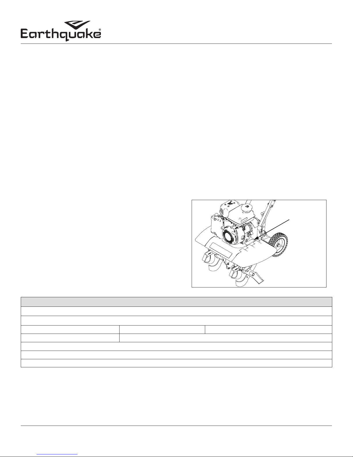
MAINTENANCE AND STORAGE
NOTICE
THE RIGHT AND LEFT SIDES
OF YOUR ROTOTILLER ARE
DETERMINED FROM THE
OPERATING POSITION AS
YOU FACE THE DIRECTION OF
FORWARD TRAVEL.
ENGINE IS SHIPPED FROM FACTORY WITHOUT
OIL. YOU MUST ADD ENGINE OIL BEFORE
STARTING ENGINE.
OPERATION
• Do not operate tiller under the inuence of alcohol or
drugs.
• Never operate tiller without guards, covers, and hoods
in place.
• Keep hands, feet, and clothing away from rotating
parts. Keep clear of tiller tines at all times.
• Tines rotate when tiller is engaged; tines rotate
when the drive safety control lever is pulled down.
Releasing the drive safety control lever to neutral
stops the tines.
• Use extreme caution when operating on or crossing
gravel drives, walks, or roads. Stay alert for hidden
hazards or trac.
• After striking a foreign object, stop the engine,
remove the wire from the spark plug, thoroughly
inspect the tiller for any damage, and repair the
damage before restarting and operating the tiller.
• If vegetation clogs the tines, stop the engine and
disconnect the spark plug wire before removing
vegetation by hand.
• If the unit should start to vibrate abnormally, stop the
engine and check immediately for the cause. Vibration
is generally a warning of trouble.
• Do not run the engine indoors; exhaust fumes are
deadly.
• Do not overload the machine capacity by attempting
to till too deep at too fast of a rate.
• Never operate the tiller without good visibility or
light.
• Be careful when tilling in hard ground. The tines may
catch in the ground and propel the tiller forward.
If this occurs, let go of the handle bars and do not
restrain the machine.
• Take all possible precautions when leaving the
machine unattended. Disengage control lever, stop
R
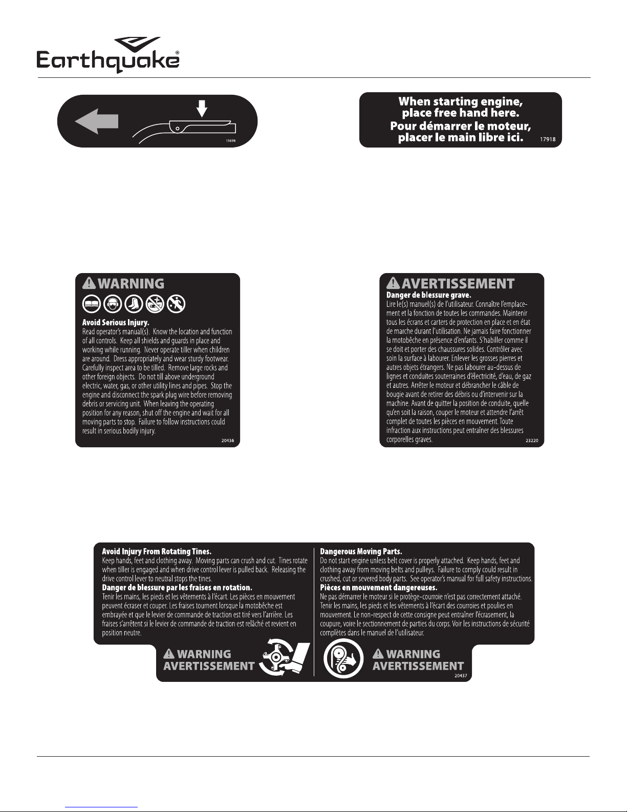
SAFETY DECALS
This rototiller unit has been designed and manufactured to
provide you with the safety and reliability you would expect
from an industry leader in outdoor power equipment manufacturing.
Although reading this manual and the safety instructions it
contains will provide you with the necessary basic knowledge
to operate this equipment safely and eectively, we have
placed several safety labels on the tiller to remind you of this
important information while you are operating the unit.
These important safety labels are shown on the next page to
help familiarize you with the location and content of the safety
messages you will see as you perform normal tilling operations. Please review these decals now, and if you have any
questions regarding its meaning or how to comply with these
instructions, reread the complete safety instruction text in this
manual. For additional questions call Earthquake®Customer
Service.
the engine, wait for all moving parts to stop, and
make certain guards and shields are in place.
• When leaving the operating position for any reason:
- shut o the engine.
- wait for all moving parts to stop.
• Keep machine, attachments and accessories in safe
working condition.
• Check shear bolts, engine mounting bolts and other
bolts at frequent intervals for proper tightness to be
sure the equipment is in safe working condition.
• To prevent accidental starting, always disconnect and
secure the spark plug wire from the spark plug before
performing tiller maintenance.
• Never run the engine indoors. Exhaust fumes are
deadly.
• Always allow muer to cool before lling the fuel
tank.
• Never store equipment with gasoline in the tank
inside a closed building where fumes may reach an
open ame or spark. Allow the engine to cool before
storing in any building.
• Always refer to the operator’s guide instructions for
important details if the tiller is to be stored for an
extended period.
6
Check for parts online at www.getearthquake.com or call 800-345-6007 M-F 8-5
Page 7
Operator's Manual
VERSA Compact Tiller and Cultivator
Part No. 15698
CLUTCH ENGAGE
Handlebar Decal
Part No. 17918
PLACE FREE HAND HERE
Engine Recoil Decal
Part No. 20436
OPERATION WARNING PICTORIALS
Drag Stake Mount Decal
Part No. 23220
OPERATION WARNING FRENCH
Drag Stake Mount Decal
Part No. 20437
TINES & BELT WARNING
Pulley Box Decal
Check for parts online at www.getearthquake.com or call 800-345-6007 M-F 8-5
7
Page 8

HAZARD SYMBOLS AND MEANINGS
O P
Operator's Manual
VERSA Compact Tiller and Cultivator
A
G H
B
C
I
D E F
J
K
L
A: Warning!
B: Avoid Injury From Rotating Tines.
C: Read Owner’s Manual Before Operating Machine.
D: Remove Objects that Could Be Thrown By This Machine.
E: Dangerous Moving Parts.
F: Be Aware of Moving and Rotating Parts.
G: Wear Ear and Eye Protection At All Times.
H: Do Not Service or Adjust Moving Parts Unless Engine is Stopped and Spark Plug
Wire is Disconnected.
I: Dress Appropriately And Wear Sturdy Footwear.
J: Toxic Fumes —Do Not Operate in Unventilated Areas.
K: Hot Surfaces.
L: Fire Hazards.
M. Do Not Use In Thunderstorms--For severe weather, stop operation of this
machine and seek shelter.
N. Team Lift--For your safety, always have at least two people when lifting this
machine.
O. Do Not Till Above Underground Utility Lines And Pipes.
P. Do Not Operate When Children Or Others Are Around.
8
Check for parts online at www.getearthquake.com or call 800-345-6007 M-F 8-5
Page 9
Operator's Manual
VERSA Compact Tiller and Cultivator
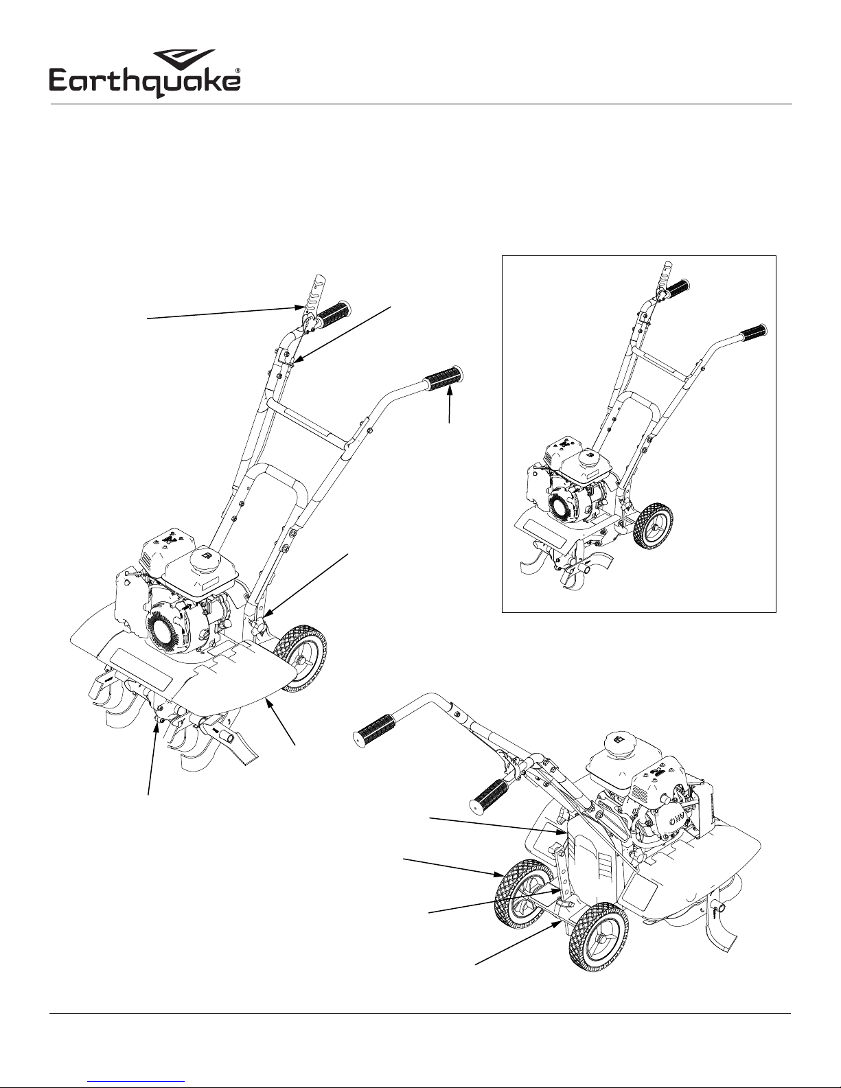
FEATURES
The advantage of the Earthquake® VERSA Compact Tiller/Cultivator, over other tillers, is its low center of gravity and the ability to
switch between tiller and cultivator in seconds with no tools! To convert your full width tiller to a narrow cultivator, just pull the
lock pins to remove the outer tines. Then simply remove the hand knob bolts and pivot the handlebar back to remove the slideon side shields. Refasten the handlebar to the pulley box to the desired height with the hand knob bolts and you’re ready to cultivate between narrow garden rows (see detailed illustrated instructions on page 16). This tiller has been engineered to the highest
standards by tilling experts who sought a light-weight, compact, and easily maneuverable tiller that can be used all season long.
ADJUSTABLE FORWARD
DRIVE
CONTROL
LEVER
CONTROL CABLE
KNOBBY
COMFORT
GRIPS
DRUABLE BRONZE
GEAR-DRIVE
TRANSMISSION
TOOL-LESS
HANDLEBAR HEIGHT
ADJUSTMENT
NARROW CULTIVATING CONFIGURATION
TOOL-LESS
REMOVAL SIDE
SHIELDS
PULLEY BOX
DURABLE
TRANSPORT
WHEELS
ADJUSTABLE DEPTH
DRAG STAKE
FIGURE 1
Check for parts online at www.getearthquake.com or call 800-345-6007 M-F 8-5
HEAVY DUTY CAST IRON
DRAG STAKE MOUNT
9
Page 10
VERSA Compact Tiller and Cultivator
a
b
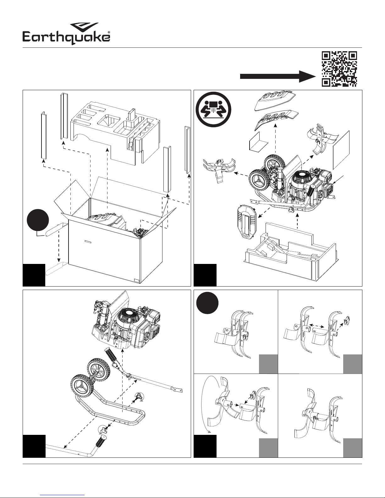
UNPACKING AND ASSEMBLY: MODELS 20015, 22662
Written instructions begin on page 14. (Instructions for model 25780 begin on page 15)
Scan QR Code for video assembly instructions and product information.
Operator's Manual
*
4X
1
2
2X
a
c
b
d
3 4
*Engine shown may not exactly match your product. Assembly instructions are not aected by this dierence.
10
c d
Check for parts online at www.getearthquake.com or call 800-345-6007 M-F 8-5
Page 11
Operator's Manual
2X
2X
VERSA Compact Tiller and Cultivator
13mm
5
A B C
C
F
J
H
2X
4X 4X
D
F
G
2X
E
6X4X
H
13mm
6
2X
H
E
A
2X
2X
I
1X
J
2X
10X
Check for parts online at www.getearthquake.com or call 800-345-6007 M-F 8-5
11
Page 12

2nd
Operator's Manual
VERSA Compact Tiller and Cultivator
1st
7
8mm
4X
2nd
2X
D
a b c
1st
2X
I
8 9
12
Check for parts online at www.getearthquake.com or call 800-345-6007 M-F 8-5
Page 13

Operator's Manual
2X
VERSA Compact Tiller and Cultivator
10mm
13mm
10
A B C
G
A
H
2X
4X 4X
D
2X
E
4X
E
H
B
F
6X4X
G
H
87+
VIPER
10W30
2X
2X
1X
J
2X
10X
I
Check for parts online at www.getearthquake.com or call 800-345-6007 M-F 8-5
13
Page 14

Operator's Manual
VERSA Compact Tiller and Cultivator
UNPACKING AND ASSEMBLY: MODELS 20015,
22662 CONTINUED
Carton Contents
• Tiller Assembly
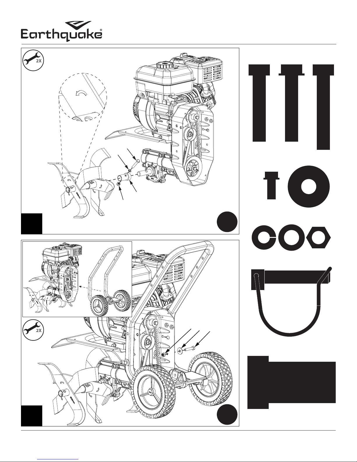
• Hardware Parts Bag:
A - 4X - M8 x 40 mm Hex Bolt
B - 4X - M8 x 40 mm Hex Flange Bolt
C - 2X - M8 x 45 mm Hex Bolt
E - 6X - M8 x 25 mm Flat Washer
F - 2X - M8 x 15 mm Spring Lock Washer
G - 2X - M8 x 16 mm Flat Washer
H - 10X - M8 Nylock Nut
I - 1X - Lock Pin
J - 2X - Tine Shaft Sleeve
• Manual Parts Bag
• Left, Right, and Middle Handlebars
• Left and Right Side Shields
• Left and Right Tine Sets
• Pulley Box Cover
D - 4X - M5 x 25 mm Hex Flange Bolt
• Drag Stake
• Bottle of 4-cycle Engine Oil
• Foam Protection, Corner Supports and Packaging
Materials
ASSEMBLY STEPS
1. Open top of carton and remove top foam piece
containing middle handlebar, hardware parts bag,
bottle of engine oil, as well as the four corner supports.
Carefully cut the four corners of the carton with a box
cutter. Do not attempt to lift tiller assembly out of box.
2. Carefully remove tiller assembly, tine sets, side shields,
pulley box cover, and remaining packaging materials
from lower foam.
3. Remove hand knob bolts from both sides of tiller.
Separate lower handlebar assembly from pulley box and
cut zip ties to remove handlebars.
4. Remove lock pin from one tine set. Slide outer tine and
rotate to align with the second hole position of inner tine,
then secure with lock pin. Repeat for other tine set.
NOTE: Ensure the lock pins and tines are correctly
installed. Lock pins must be installed so that the pin
enters the hole in the tine from the front of the tiller,
and so the wire bale hinges over the top of the tine pipe
and latches to the protruding pin on the back side of
the tine. Tines can inadvertently detach during tilling if
lock pins are not installed correctly! SEE FIGURES 23
5. Check that arrows are pointing in the direction of forward
rotation and slide left tine set over tine shaft sleeve,
align mounting holes with the left tine shaft, and secure
with the M8 x 45 mm Hex Bolt, M8 x 15 mm Spring Lock
Washer, and M8 Nylock Nut. Tighten with two 13mm
wrenches. Repeat for right tine set on right tine shaft.
NOTICE
HANDLE ROTOTILLER WITH CARE. DO NOT DAMAGE
FORWARD CABLE WHEN TRANSPORTING OR
OPERATING.
LOCK PIN HINGE
LOCK PIN INSTALLED CORRECTLY
FIGURE 2
LOCKPIN INSTALLED INCORRECTLY
FIGURE 3
Tines can be congured for multiple tilling situations.
SEE FIGURE 4
a. Wide Tilling - Install according to Assembly Step 5
b. Narrow Tilling - Remove outer tines and lock pins and
install on opposite tine shaft with the directional arrows
pointing in the direction of forward rotation.
c. Narrow Cultivating - Remove outer tines and lock pins.
WIDE
TILLING
21 INCHES
FIGURE 4
NARROW
TILLING
16 INCHES
NARROW
CULTIVATING
11 INCHES
14
Check for parts online at www.getearthquake.com or call 800-345-6007 M-F 8-5
Page 15

Operator's Manual
VERSA Compact Tiller and Cultivator
6. Align lower handlebar assembly mount holes with lower
mount holes on pulley box. Place one M8 x 25 mm Flat
Washer on one M8 x 40 mm Hex Bolt and insert through
lower mount hole of lower handlebar assembly and
pulley box. Place one M8 Nylock Nut on bolt and tighten
with two 13mm wrenches. Repeat for other side.
7. Rotate lower handlebar assembly away from engine to
provide adequate clearance to install side tine shields
Slide left and right side shields onto center tine shield.
Align side shield grooves with center tine shield and push
until an audible click is heard and/or felt. This indicates
that the tine shield has engaged with the shield lock
and is secured all the way on. Rotate lower handlebar
assembly up towards engine and insert hand knob bolts
through upper mount holes and tighten. Hand knob
bolts can be inserted into one of two sets of holes depending
on desired handlebar height.
8. Remove four M5 x 12 mm Hex Flange Bolts from pulley
box cover. Place pulley box cover onto pulley box and
secure with the four M5 x 12 mm Hex Flange Bolts using
an 8mm wrench.
9. Slide drag stake through drag stake mount and secure
with lockpin at the desired depth.
10. Align right handlebar mount holes with lower handlebar
assembly mount holes at one of two height positions.
Secure right handlebar with two M8 x 40 mm Hex Flange
Bolts, two M8 x 25 mm Flat Washers, and Two M8 Nylock
Nuts and hand tighten. Repeat for left handlebar. Align
middle handlebar with mount holes of right and left
handlebars. Secure middle handlebar with two M8 x 40
mm Hex Bolts, two M8 x 16 mm Flat Washers, and two
M8 Nylock Nuts. Tighten all handlebar hardware with a
combination of 10mm and 13mm wrenches. Use two zip
ties to secure the forward cable. (optional).
Fill Engine Crankcase
1. Add oil according to engine manual. DO NOT OVERFILL.
Use a clean, high quality detergent oil. Use no special
additives with recommended oils. DO NOT MIX OIL
WITH GASOLINE. Oil level must be full. Check the oil
level by removing oil ll plug. Oil level should be up to
the bottom of the ll plug opening.
2. Always check oil level before starting engine. Refer to
engine manual for capacity and type of oil to use.
Fill Fuel Tank
1. Add gasoline according to engine manual. DO NOT
OVERFILL. Use 87+ octane unleaded ethanol-free
gasoline. If an ethanol blend must be used, use ethanol
fuel stabilizer. DO NOT MIX OIL WITH GASOLINE.
2. Always check gasoline level before starting engine. Refer
to engine manual for capacity and type of gasoline to
use.
NOTICE
ENGINE IS SHIPPED FROM FACTORY WITHOUT
OIL. YOU MUST ADD ENGINE OIL BEFORE
STARTING ENGINE.
UNPACKING AND ASSEMBLY: MODEL 25780
Written instructions begin on page 18.
Scan QR Code for video assembly instructions and
product information.
4X
1
MIDDLE
HANDLEBAR
LEFT
HANDLEBAR
10W30 OIL
BOTTLE
RIGHT
HANDLEBAR
OUTER TINES
MANUAL
PARTS BAG
OUTER TINE
SHIELDS
HARDWARE
PARTS BAG
Check for parts online at www.getearthquake.com or call 800-345-6007 M-F 8-5
2
15
Page 16

DRAG STAKE
RIGHT
OUTER
TINE
LOCK PINS
LEFT
OUTER
TINE
Operator's Manual
VERSA Compact Tiller and Cultivator
3 4
LOCK PIN
REMOVE
HAND
KNOBS
2X
a b
5
*Engine shown may not exactly match your product. Assembly instructions are not aected by this dierence.
16
2X 2X
c
d e
Check for parts online at www.getearthquake.com or call 800-345-6007 M-F 8-5
Page 17

Operator's Manual
2X
VERSA Compact Tiller and Cultivator
10mm
13mm
D
A
E
2X
F
6
87+
VIPER
10W30
7
C
E
B
A
B
C D E
F
4X
2X
4X
6X4X 2X
1X
Check for parts online at www.getearthquake.com or call 800-345-6007 M-F 8-5
17
Page 18

Operator's Manual
VERSA Compact Tiller and Cultivator
UNPACKING AND ASSEMBLY: MODEL 25780
CONTINUED
Carton Contents
• Tiller Assembly
• Hardware Parts Bag:
A - 2X - M8 x 40 mm Hex Bolt
B - 4X - M8 x 40 mm Hex Flange Bolt
C - 4X - M8 x 25 mm Flat Washer
D - 2X - M8 x 16 mm Flat Washer
E - 6X - M8 Nylock Nut
F - 1X - Lock Pin
• Manual Parts Bag
• Left, Right, and Middle Handlebars
• Left and Right Side Shields
• Left and Right Outer Tines
• Bottle of 4-cycle Engine Oil
• Packaging Materials
ASSEMBLY STEPS
1. Open top of carton and remove top cardboard piece.
Carefully cut the corners of the carton with a box cutter.
Do not attempt to lift tiller assembly out of box.
2. Carefully remove handlebars, outer tines, side shields,
parts bags, bottle of oil, and remaining packaging
materials from underneath and around the tiller
assembly.
3. Remove drag stake from tiller assembly by removing the
lock pin and setting both aside.
4. Remove lock pin from one inner tine. Check that arrows
on tines are pointed in the direction of forward rotation
and slide outer tine so that it aligns with the second hole
position of inner tine. Secure with the lock pin. Repeat for
other outer tine.
NOTE: Ensure the lock pins and tines are correctly
installed. Lock pins must be installed so that the pin
enters the hole in the tine from the front of the tiller,
and so the wire bale hinges over the top of the tine pipe
and latches to the protruding pin on the back side of the
tine. Tines can inadvertently detach during tilling if lock
pins are not installed correctly! SEE FIGURES 56
Tines can be congured for multiple tilling situations.
SEE FIGURE 7
a. Wide Tilling - Install according to Assembly Step 4
b. Narrow Tilling - Remove outer tines and lock pins and
install on opposite tine shaft with the directional arrows
pointing in the direction of forward rotation.
c. Narrow Cultivating - Remove outer tines and lock
pins.
5. Tine side shield installation.
a. Remove hand knob bolts from lower handlebar
assembly.
NOTICE
HANDLE ROTOTILLER WITH CARE. DO NOT DAMAGE
FORWARD CABLE WHEN TRANSPORTING OR
OPERATING.
LOCK PIN HINGE
LOCK PIN INSTALLED CORRECTLY
FIGURE 5
LOCKPIN INSTALLED INCORRECTLY
FIGURE 6
b. Rotate lower handlebar assembly away from engine
to provide adequate clearance to install side tine shields.
c. Slide left and right side shields onto center tine shield.
Align side shield grooves with center tine shield and push
until an audible click is heard and/or felt. This indicates
that the tine shield has engaged with the shield lock and
is secured all the way on.
d. Rotate lower handlebar assembly up towards engine.
WIDE
TILLING
21 INCHES
FIGURE 7
NARROW
TILLING
16 INCHES
NARROW
CULTIVATING
11 INCHES
18
Check for parts online at www.getearthquake.com or call 800-345-6007 M-F 8-5
Page 19

e. Insert hand knob bolts through upper mount holes
UPPER
and tighten. Hand knob bolts can be inserted into one of
two sets of holes depending on desired handlebar height.
6. Slide drag stake through drag stake mount and secure
with lockpin at the desired depth.
7. Align right handlebar mount holes with lower handlebar
assembly mount holes at one of two height positions.
Secure right handlebar with two M8 x 40 mm Hex Flange
Bolts, two M8 x 25 mm Flat Washers, and Two M8 Nylock
Nuts and hand tighten. Repeat for left handlebar. Align
middle handlebar with mount holes of right and left
handlebars. Secure middle handlebar with two M8 x 40
mm Hex Bolts, two M8 x 16 mm Flat Washers, and two
M8 Nylock Nuts. Tighten all handlebar hardware with a
combination of 10mm and 13mm wrenches. Use two zip
ties to secure the forward cable. (optional).
NOTICE
ENGINE IS SHIPPED FROM FACTORY WITHOUT
OIL. YOU MUST ADD ENGINE OIL BEFORE
STARTING ENGINE.
Operator's Manual
VERSA Compact Tiller and Cultivator
WARNING
THIS INFORMATION IS PROVIDED HERE ONLY
TO INTRODUCE THE CONTROLS. DO NOT START
THE ENGINE AT THIS TIME. PLEASE READ THIS
SECTION AND ALL OPERATING AND SAFETY
INSTRUCTIONS BEFORE STARTING YOUR TILLER.
• AS A SAFETY PRECAUTION, THE DRIVE
SAFETY CONTROL LEVER WILL NOT LOCK IN
THE FORWARD POSITION.
• TO STOP THE TINES AT ANY TIME, RELEASE
THE DRIVE SAFETY CONTROL LEVER.
• PROTECTIVE FOOTWEAR MUST BE WORN
WHILE OPERATING THIS PRODUCT.
• ENGINE SHOULD BE OFF BEFORE ADJUSTING
ANY CONTROLS.
• DO NOT ADJUST TILLING DEPTH UNLESS
DRIVE SAFETY CONTROL LEVER IS RELEASED
TO THE NEUTRAL POSITION.
Fill Engine Crankcase
1. Add oil according to engine manual. DO NOT OVERFILL.
Use a clean, high quality detergent oil. Use no special
additives with recommended oils. DO NOT MIX OIL
WITH GASOLINE. Oil level must be full. Check the oil
level by removing oil ll plug. Oil level should be up to
the bottom of the ll plug opening.
2. Always check oil level before starting engine. Refer to
engine manual for capacity and type of oil to use.
Fill Fuel Tank
1. Add gasoline according to engine manual. DO NOT
OVERFILL. Use 87+ octane unleaded ethanol-free
gasoline. If an ethanol blend must be used, use ethanol
fuel stabilizer. DO NOT MIX OIL WITH GASOLINE.
2. Always check gasoline level before starting engine. Refer
to engine manual for capacity and type of gasoline to
use.
OPERATION
CONTROLS
Drive Safety Control Lever
Pulling down on drive safety control lever engages the tines.
Releasing the drive safety control lever to a neutral position
disengages the tines.
Belt Tension Adjustment
Proper belt tension is critical to good performance. After 1/2
hour of operation, all cables may have to be adjusted due to
initial stretch. Thereafter, check tension after every 10 hours of
operation. Proper tension is achieved when the beehive spring
extends 1/8” - 1/4” when drive lever is engaged.
To increase belt tension do as follows:
1. Loosen upper jam nut. SEE FIGURE 8
2. Tighten the lower jam nut in 1/8” increments, making
sure not to over adjust the tension.
3. Check adjustment by measuring the beehive spring
extension when drive lever is engaged. (Proper spring
extension is 1/8” - 1/4”) SEE FIGURE 8
JAM NUT
LOWER
JAM NUT
FIGURE 8
Z-BEND
LINKAGE
DRIVE SAFETY
CONTROL LEVER
DISENGAGED
FORWARD
CABLE
BEEHIVE
SPRING
1/8” - 1/4” STRETCH
Check for parts online at www.getearthquake.com or call 800-345-6007 M-F 8-5
19
Page 20

Operator's Manual
VERSA Compact Tiller and Cultivator
4. When proper adjustment is achieved, tighten upper jam
nut.
NOTE: This procedure can be repeated until conduit
adjustment bolts are fully adjusted. The Z-bend
linkage can also be adjusted by inserting in the
additional linkage holes on the drive control lever.
If no more adjustment can be made, belt may need
to be replaced.
Drag Stake
Tilling depth is controlled by the height of the drag stake.
SEE FIGURE 9
To adjust tilling depth do as follows:
1. Remove lock pin.
2. Raise the drag stake to position tines at chosen tilling
depth. Lowering the drag stake will allow for deeper
tilling.
3. Align hole in drag stake with hole in drag stake mount
and replace lock pin.
NOTE: Raise drag stake all the way when transporting
tiller. Lower the drag stake all the way to maintain
control of the tiller in harder soil conditions.
DRAG STAKE
LOCK PIN
DRAG STAKE MOUNT
FIGURE 9
Height Adjustments
Handlebar height can be adjusted in two ways to accommodate a total of four possible user heights. SEE FIGURE 10
To adjust height at handlebars do as follows
1. Remove left and right handlebar mount hardware.
2. Align handlebar at desired height and attach hardware.
To adjust height at pulley box do as follows
1. Remove hand knob bolts from box and rotate handlebars
to desired height then reattach hand knob bolts.
HANDLEBAR
ADJUSTMENT HOLES
(2 POSITIONS)
PULLEY BOX
MOUNT HOLES
(2 POSITIONS)
FIGURE 10
HIGHEST
POSITION
LOWEST
POSITION
PRESTART INSPECTION
1. Make sure all safety guards are in place and all nuts and
bolts are secure.
2. Check oil level in engine crankcase. See your engine
manual for procedure and specications.
3. Inspect air cleaner for cleanliness. See your engine
manual for procedure.
4. Check the fuel supply. Fill the fuel tank no closer than 1
inch from top of tank to provide space for expansion. See
your engine manual for fuel recommendations.
5. Be sure spark plug wire is attached and spark plug is
tightened securely.
6. Check drag stake position.
7. Examine underneath and around engine for signs of oil or
fuel leaks.
8. Inspect fuel hoses for tightness and fuel seepage.
9. Look for signs of engine damage.
10. Remove excessive debris from muer area and recoil
starter.
START-UP
The controls required to start and run the rototiller are located
on the engine.
Models 20015, 22662, 25780:
The throttle speed control is located above the pull-start recoil
and is indicated by a rabbit for FAST and a turtle for SLOW.
Models 20015, 25780:
The choke lever is located above the air cleaner cover. The ON/
20
Check for parts online at www.getearthquake.com or call 800-345-6007 M-F 8-5
Page 21

Operator's Manual
VERSA Compact Tiller and Cultivator
DANGER
DO NOT START YOUR TILLER UNTIL YOU HAVE
READ AND UNDERSTAND THIS MANUAL AND THE
SECTIONS IN THIS MANUAL COVERING SAFETY
AND OPERATION.
ALWAYS PERFORM THE PRESTART INSPECTION
CHECKLIST BEFORE STARTING THE ENGINE.
PRACTICE OPERATING THE CONTROLS AND
TILLER WITH TINES OUT OF GROUND BEFORE
BEGINNING TO TILL. IT IS IMPORTANT THAT YOU
KNOW HOW TO USE THE TILLER PROPERLY: KEEP
CONTROL AT ALL TIMES, STOP THE TINE FROM
TURNING, AND STOP THE ENGINE IF NECESSARY.
IF YOU DO NOT KNOW HOW TO DO THESE THINGS,
READ THE CONTROLS AND SAFETY SECTIONS
BEFORE PROCEEDING.
ALWAYS MAINTAIN CONTROL OF YOUR TILLER.
ONLY OPERATE TILLER IN SOIL CONDITIONS THAT
ARE CONDUCIVE TO MAINTAINING CONTROL
OF THE TILLER. DO NOT OPERATE TILLER IN
CONDITIONS THAT CONTAIN ROCKS, FOREIGN
OBJECTS, OR ANY OTHER MATERIAL THAT IS
NOT SOIL. IF YOUR TILLER BUMPS, JERKS, OR
LURCHES, LET GO OF THE HANDLEBARS AND THE
DRIVE CONTROL LEVER IMMEDIATELY SO THAT
THE TINES STOP TURNING.
CAUTION MUST BE TAKEN WHEN SELECTING
TILLING DEPTH. LOSS OF CONTROL COULD
RESULT IF YOU ATTEMPT TO TILL IN CERTAIN SOIL
CONDITIONS WITH THE DRAG STAKE SET IN TOO
HIGH OF A POSITION.
STOP THE ENGINE AND REMOVE SPARK PLUG
WIRE BEFORE REMOVING MATERIAL FROM THE
TINES BY HAND OR ANY OTHER METHOD.
ENGINE AND SURROUNDING PARTS BECOME
EXTREMELY HOT DURING NORMAL OPERATION.
TEMPERATURE OF MUFFLER AND NEARBY AREAS
MAY EXCEED 150°F 66°C. AVOID THESE AREAS.
ALLOW ENGINE TO COOL COMPLETELY BEFORE
TOUCHING THESE HOT SURFACES. THESE AREAS
WILL CAUSE SERIOUS BURN INJURIES IF TOUCHED
BEFORE THE ENGINE HAS COOLED.
ALWAYS KEEP HANDS AND FEET CLEAR OF
ROTATING MACHINE PARTS.
OFF switch is located on the side of the blower housing closest
to the recoil pull handle.
Model 22662:
The choke lever is located below the air cleaner cover. The
ON/OFF switch is located on the front left side of the blower
housing.
CAUTION
DO NOT USE CHOKE CONTROL TO STOP ENGINE.
BACKFIRE OR ENGINE DAMAGE MAY OCCUR!
TO STOP THE ENGINE AT ANY TIME, MOVE
THROTTLE CONTROL TO THE OFF OR STOP
POSITION, OR TURN THE ON/OFF SWITCH TO OFF.
ALWAYS RELEASE DRIVE SAFETY CONTROL LEVER
TO NEUTRAL POSITION BEFORE ADJUSTING THE
DEPTH OF THE DRAG STAKE.
ENGINE IS SHIPPED FROM FACTORY WITHOUT
OIL. YOU MUST ADD ENGINE OIL BEFORE
STARTING ENGINE.
Additional engine operation and related precautions and
procedures can be found in the engine manufacturer’s manual
that accompanies each tiller.
COLD STARTS
1. Turn the ON/OFF switch to the ON position.
2. Move choke lever to FULL CHOKE position.
3. Move throttle lever to half way between the SLOW
position and the FAST position.
4. Pull starting rope out slowly one time and allow to
return normally.
5. Pull starting rope out rapidly, and allow rope to return
normally. Repeat until engine starts.
6. When engine starts, gradually move choke lever to
run position and increase throttle speed to the FAST
position for tilling.
Restarting A Warm Engine
Restarting an engine that is already warm from previous
running does not normally require use of the choke.
1. Turn the ON/OFF switch to the ON position.
2. Move throttle lever to half way between SLOW and
FAST.
3. Pull starting rope out rapidly until engine starts. Allow
rope to return normally. Repeat until engine starts.
4. Adjust throttle speed to the FAST position for tilling.
Operating Speed
For normal tilling, set the throttle lever to FAST.
Shutting Down
To stop the engine at any time, turn the ON/OFF switch to the
OFF position. To stop tines at any time, release the drive safety
control lever to the neutral position.
Tilling
1. Adjust the drag stake to desired tilling depth.
NOTE: Raise drag stake up one hole at a time, testing tiller
Check for parts online at www.getearthquake.com or call 800-345-6007 M-F 8-5
21
Page 22

Operator's Manual
VERSA Compact Tiller and Cultivator
operation after each raise. Raising drag stake too high
can result in loss of control of tiller!
2. Move the throttle control to FAST.
3. Place the tiller in motion by pushing down on the drive
safety control lever. This will engage the tines.
MAINTENANCE AND STORAGE
Your rototiller has been designed and produced by the industry’s leading manufacturer of outdoor power equipment to
provide you with years of reliable operation.
Please read the maintenance schedule in this manual for the
tiller, and the maintenance schedule and recommendations in
the accompanying engine manual. Observe these recommendations to extend the life of your product.
Good maintenance is essential for safe, economical, and
trouble-free operation. Keeping your tiller in top running
condition will prolong its life, and help you obtain optimum
performance. It will also help reduce air pollution. To help
you properly care for your engine, the following pages include
a maintenance schedule, routine inspection procedures, and
simple maintenance procedures using basic hand tools. Other
service tasks that are more dicult, or require special tools, are
best handled by professionals and are normally performed by
a technician or other qualied mechanic.
Maintenance, replacement or repair of the emissions control
devices and systems may be performed by any non-road
engine repair establishment or individuals. However, items
must be serviced by an authorized dealer to obtain “no charge”
emissions control warranty service.
The maintenance schedule applies to normal operating conditions. If you operate your tiller under unusual conditions, such
as sustained high-load or high-temperature operation, or use
in unusually wet or dusty conditions, consult your servicing
dealer for recommendations applicable to your individual
needs and use.
Servicing The Rototiller
The following information will help you make the necessary
checks and perform the procedures required to follow the
normal care recommendations made for your rototiller unit.
If you prefer, your local authorized dealer can make these
checks and perform the required procedures for you.
BELT MAINTENANCE
Check Belt Tension as follows:
Belt tension may decrease over time. It may need to be adjusted within the rst half hour of operation, and should be
checked after every ten hours of operation. Proper adjustment
will assure long belt life. Too much or too little belt tension will
cause premature belt failure.
An indication that the belt may need to be adjusted can be
heard as a continuous squealing sound when the engagement
lever is compressed, or the belt slips and tines won’t turn (see
page 19).
MAINTENANCE SCHEDULE
Maintenance
Operation
Check belt tension 22 X
Change drive belt 22-23 X
Engine maintenance 24,EM X X X
Check or ll engine
crankcase
Clean tine axle shaft
& lubricate parts
EM = See engine manual
1 Change oil after rst 5-8 hours of use, then after every 50 hours.
Change oil every 25 hours when operating under heavy load or in high
temperatures.
2 Clean tine axle shaft and lubricate each season or every 10 hours,
whichever comes rst.
NOTE: A short buzzing noise can be heard when
engagement lever is released. This is normal, caused
by the teeth of the cog belt catching the wire guide,
stopping the rotation of the belt. This does not require
the belt tension to be adjusted.
To check and adjust the forward belt tension:
1. Turn o engine. Engine must be cool.
2. Remove spark plug wire from spark plug and secure.
3. Remove pulley box cover by removing four cover bolts.
SEE FIGURE 11
4. With drive safety control lever in the neutral position,
measure length of spring when in its relaxed state.
5. Pull down on drive safety control lever and measure
length of spring when extended. Ideal length would be
1/8” - 1/4” longer. SEE FIGURE 12
6. Replace pulley box cover.
Change Drive Belt as follows:
1. Turn o engine. Engine must be cool.
2. Remove spark plug wire from spark plug and secure.
3. Remove pulley box cover by removing four bolts.
SEE FIGURE 11
4. Remove the belt from the engine pulley as follows:
a. Gently pull the engine recoil rope to rotate the pulley.
b. With the pulley turning, force the belt out of the
groove and slide the belt free of the engine pulley.
c. Pull the belt down and out of the way.
Page
24,EM X X 1
24 2
Before
Each Use
10
hours
50
hours
22
Check for parts online at www.getearthquake.com or call 800-345-6007 M-F 8-5
Page 23

Operator's Manual
CAP/WIRE
VERSA Compact Tiller and Cultivator
COVER
BOLT
PULLEY BOX
COVER
FIGURE 11
d. Push the belt down and away from the transmission
pulley to remove.
5. Install new belt as follows:
a. Place belt in transmission pulley groove.
b. Gently pull the engine recoil rope to rotate the pulley
while forcing the belt into the groove.
6. Replace pulley box cover.
7. Recheck belt tension and adjust if necessary
8. Attach spark plug wire.
DRIVE SAFETY
CONTROL LEVER
DISENGAGED
BEEHIVE
SPRING
FORWARD
CABLE
DRIVE BELT
(P/N 20343)
WARNING
TO PREVENT ACCIDENTAL
STARTING:
ENGINE MUST BE TURNED OFF
AND COOL, AND SPARK PLUG
CAP/WIRE MUST BE REMOVED
AND SECURED FROM SPARK
PLUG BEFORE CHECKING
AND ADJUSTING ENGINE OR EQUIPMENT.
SPARK PLUG
SPARK PLUG
NOTICE
CHECK FORWARD BELT TENSION REGULARLY.
TOO MUCH OR TOOL LITTLE TENSION WILL CAUSE
PREMATURE BELT FAILURE.
DO NOT USE CHOKE CONTROL TO STOP ENGINE.
BACKFIRE OR ENGINE DAMAGE MAY OCCUR!
TO STOP THE ENGINE AT ANY TIME, MOVE
THROTTLE CONTROL TO THE OF OR STOP
POSITION, OR SET THE ON/OFF SWITCH TO OFF.
NEVER RUN ENGINE WITHOUT COMPLETE AIR
CLEANER INSTALLED ON ENGINE. ENGINE CAN
OVERHEAT AND BECOME DAMAGED IF DEBRIS
BLOCKS THE COOLING SYSTEM OR ROTATING
SCREEN.
DANGER
DO NOT STORE TILLER IN AN UNVENTILATED
AREA WHERE FUEL FUMES MAY REACH FLAME,
SPARKS, PILOT LIGHTS, OR AN IGNITED OBJECT.
DRAIN FUEL OUTDOORS AWAY FROM ANY
IGNITION SOURCES. USE ONLY APPROVED FUEL
CONTAINERS.
ENGINE AND SURROUNDING PARTS BECOME
EXTREMELY HOT DURING NORMAL OPERATION.
TEMPERATURE OF MUFFLER AND NEARBY AREAS
MAY EXCEED 150°F 66°C. AVOID THESE AREAS.
ALLOW ENGINE TO COOL COMPLETELY BEFORE
TOUCHING THESE HOT SURFACES. THESE AREAS
WILL CAUSE SERIOUS BURN INJURIES IF TOUCHED
BEFORE THE ENGINE HAS COOLED.
ALWAYS KEEP HANDS AND FEET CLEAR OF
ROTATING MACHINE PARTS.
FIGURE 12
Check for parts online at www.getearthquake.com or call 800-345-6007 M-F 8-5
1/8” - 1/4”
STRETCH
23
Page 24

ENGINE MAINTENANCE
Refer to the engine manual included in your parts packet for
information on engine maintenance. Your engine manual
provides information and a maintenance schedule for performing
the following tasks:
1. Check oil level before each use or after every 8 hours of
operation.
2. Change oil after rst 5-8 hours of operation. Change oil while
engine is warm. Rell with new oil of recommended grade.
4. Check spark plug seasonally or every 100 hours of operation.
5. Service air cleaner.
6. Keep engine and parts clean.
7. Check engine and equipment often for loose nuts and bolts,
keep these items tightened.
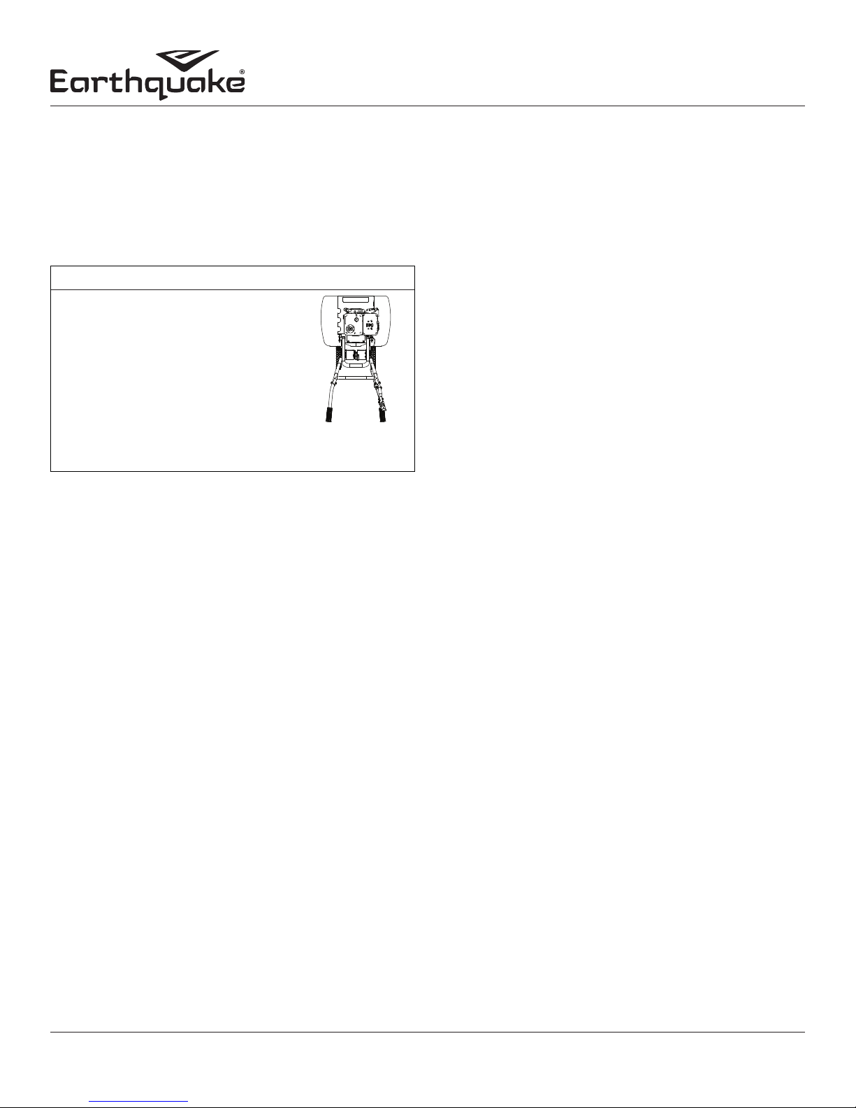
CHECK OR FILL ENGINE CRANKCASE
1. To change the oil, rst remove the left side shield from the
tiller. Then lock drag stake into deepest position and gently
tip tiller to the left, resting it in a tilted position on its left outer
tine, wheel, and drag stake. Remove oil ll plug with the tiller
resting in the tilted position until all of the oil has been drained
into an appropriate receptacle. SEE FIGURE 13. Wipe up any
spilled oil residue and dispose of oil properly according to
local laws and/or ordinances.
2. Return tiller back to its upright level position and add oil
according to engine manual. Do not overll. Use a clean,
high quality detergent oil. Use no special additives with
recommended oils. Do not mix oil with gasoline. Oil level
must be full. Check the oil level by removing oil ll plug. Oil
level should be up to the bottom of the ll plug opening on
most engines.
3. Always check oil level before starting engine. Refer to engine
manual for capacity and type of oil to use.
FIGURE 13
CLEAN TINE AXLE SHAFT
1. Turn o engine. Engine must be cool.
Operator's Manual
VERSA Compact Tiller and Cultivator
WARNING
PRACTICE SAFETY AT ALL TIMES. ENGINE MUST
BE TURNED OFF AND ALLOWED TO COOL, AND
SPARK PLUG WIRE MUST BE DISCONNECTED
AND SECURED BEFORE ATTEMPTING ANY
MAINTENANCE OR REPAIR.
FAILURE TO COMPLY WITH THIS SAFETY
REQUIREMENT CAN RESULT IN SERIOUS
PERSONAL INJURY TO YOU OR BYSTANDERS.
2. Remove spark plug wire and secure from spark plug.
3. Remove all vegetation, string, wire, and other material that
may have accumulated on the axle between the inside set of
tines and the seal on the transmission housing.
4. Replace spark plug wire.
LUBRICATION
Proper lubrication of moving mechanical parts is critical for
proper care and maintenance. Oil the moving parts using a 30
weight oil.
STORAGE
PREPARE FOR STORAGE
Follow the steps below to prepare your tiller for storage. Read
your engine manual for detailed instructions on preparing the
engine for storage.
1. Protect tines and tine shafts from rust:
- Coat the tine shaft lightly with axle grease.
2. Drain fuel system completely following engine manufacturer’s
instructions or add fuel stabilizer to prevent fuel from
gumming up during extended storage period.
3. While engine is still warm, drain the oil from the engine. Rell
with fresh oil of the recommended grade.
4. Clean external surfaces, engine and cooling fan.
5. Remove spark plug, pour one ounce of SAE 30 oil into spark plug hole.
6. Plug hole and pull starter cord slowly to distribute oil evenly
in cylinder head area.
7. Reinstall spark plug.
8. Transport unit to a suitable storage location. If you have chosen
to use a fuel stabilizer and have not drained the fuel system,
follow all safety instructions and storage precautions in this
manual to prevent the possibility of re from the ignition of
gasoline fumes. Remember, gasoline fumes can travel to distant
sources of ignition and ignite, causing risk of explosion and re.
9. If there is any possibility of unauthorized use or tampering,
remove the spark plug and store it in a safe place before
storing the rototiller unit. Be sure to plug the spark plug hole
to prevent foreign material from entering.
24
Check for parts online at www.getearthquake.com or call 800-345-6007 M-F 8-5
Page 25

Operator's Manual
VERSA Compact Tiller and Cultivator
TROUBLESHOOTING AND REPAIR
Troubleshooting Guide
While normal care and routine maintenance will extend the life of your rototiller, prolonged or constant use may eventually
require that service be performed to allow it to continue operating properly. The troubleshooting guide below lists the most
common problems, causes and remedies.
PROBLEM REMEDY/ACTION
Engine will not start • Add gas to gas tank
• Connect spark plug wire to spark plug
• ON/OFF switch must be turned ON and engine choked for a cold
start
Engine runs rough, oods during operation • Clean or replace air cleaner
Engine is hard to start • Drain old fuel and replace with fresh. Use gas stabilizer at end of
season
• Make sure spark plug wire is securely attached to spark plug
• Drive safety control lever must be released to neutral to start the
engine
Engine misses or lacks power • Raise the drag stake for shallower tilling
• Clean or replace air cleaner
• Improper carburetor adjustment, take to authorized
engine service center
• Replace spark plug and adjust gap
• Drain and rell gas tank with fresh gasoline
Tiller moves forward during starting • Drive safety control lever must be released to neutral
to start the engine
• Check belt tension
Tiller is dicult to control when tilling
(Machine jumps or lurches forward)
Belts squeal in forward operation • Adjust belt tension with engagement cable
Constant buzzing sound is heard while drive safety control lever is
compressed
Excessive heat build up in transmission/tine area during tilling • Remove vegetation
* Please contact 800-345-6007 for service parts
• Lower engine speed in hard ground
• Lower the drag stake for greater resistance and control of the tiller
• Replace drive belt
• Properly space wire guide from idler pulley to clear belt when
engaged
• Adjust engagement cable
NOTE: If drive safety control lever is fully compressed, wire guide
is properly adjusted, and cable has reached full adjustment
and buzzing persists, the belt may be stretched and needs to be
replaced. *
• Check transmission lubrication and ll if needed
Check for parts online at www.getearthquake.com or call 800-345-6007 M-F 8-5
25
Page 26

ILLUSTRATED PARTS BREAKDOWN
Handle Bar Assembly
4
5
6
7
7
8
Operator's Manual
VERSA Compact Tiller and Cultivator
1
2
3
9
10
12
11
13
16
14
14, 15
17
18
22
23
24
19
23
7
21
25
20
8 18
33
30,32
8
18
28
26
18
30,31
34
30
35
29
27
26
Check for parts online at www.getearthquake.com or call 800-345-6007 M-F 8-5
Page 27

VERSA Compact Tiller and Cultivator
ITEM # PART # DESCRIPTION QTY
1 13833 GRIP 1 IN KNOB TEXTURED 2
2 23548 HANDLEBAR RIGHT 1
3 13599 NUT M6 X 1.0 NYLOCK FLANGE 1
4 23540 LEVER CLUTCH FORWARD 1
5 13159 BOLT M5 X 0.8 X 7 SHOULDER 1
6 W1200114 WASHER M8 SPRING LOCK 1
7 12770 BOLT M8 X 1.25 X 40 HEX HEAD 5
8 3245 WASHER M8 X 24 X 2 FLAT 10
9 3308 WASHER M5 X 10 X 1.0 FLAT 1
10 3248 NUT M5 X 0.8 NYLOCK FLANGE 1
11 20347 BOLT M6 X 1.0 X 35 SOCKET HEAD 1
12 W1200117 WASHER M6 X 13 X 1.75 FLAT 1
13 13508 BAR NUT M8 X 1.25 1
14 20054 CABLE DRIVE CONTROL 1
15 4620 JAM NUT M8 X 1.25 2
16 23563 BRACKET CABLE MOUNT 1
17 20052 HANDLEBAR MIDDLE 1
18 400023 NUT M8 X 1.25 NYLOCK 10
19 19922 BOLT M8 X 1.25 X 40 HEX FLANGE 4
20 20053 FRAME HANDLEBAR MOUNT 1
21 20057 BOLT M8 THREE STAR KNOB 2
22 25985 BOLT M12 X 1.75 X 104 SHOULDER 2
23 10517 WASHER 16 X 25 X 2.5 MM FLAT 4
24 15856 WHEEL 8 X 5/8 IN GREY 2
25 18098 BOLT M8 X 1.25 X 45 HEX HEAD 2
26 17987 NUT M12 X 1.75 NYLOCK 2
27 20056 PLUG SQUARE TUBE END NYLON 2
28 24814 DRAG STAKE MOUNT CASTING 1
29 18039 LOCK PIN 8 X 40 MM 1
30 18131 DRAG STAKE ASSEMBLY 1
31 W1265V0904 BOLT M8 X 1.25 X 20 HEX HEAD 1
32 13601 NUT M8 X 1.25 THREE STAR KNOB 1
33 20050 HANDLEBAR LEFT 1
34* 20413 HARDWARE PARTS BAG 20015, 22662 1
34** 25783 HARDWARE PARTS BAG 25780 1
35*** 25785 MANUAL PARTS BAG 20015, 25780 1
35**** 24848 MANUAL PARTS BAG 22662 1
* Models 20015, 22662 only
** Model 25780 only
*** Models 20015, 25780 only
**** Model 22662 only
Operator's Manual
Check for parts online at www.getearthquake.com or call 800-345-6007 M-F 8-5
27
Page 28

ILLUSTRATED PARTS BREAKDOWN
Chassis Assembly
Operator's Manual
VERSA Compact Tiller and Cultivator
39
MODEL 22662
ENGINE MOUNT PARTS
39
18
31
38
7
37
7
28
36
17
7
6
7
33
32
6
16
31
30
29
6
12
13
11
16
12
15
14
10
9
7
15
8
7
6
5
4
MODEL 22662
ENGINE MOUNT PARTS
1,3
1,2
1
38
41
40
34
6
28
27
35
22
21
43
19
42
MODEL 22662 PULLEY
MOUNT PARTS
7
26
25
24
23
22
21
20
19
28
Check for parts online at www.getearthquake.com or call 800-345-6007 M-F 8-5
Page 29

Operator's Manual
VERSA Compact Tiller and Cultivator
ITEM # PART # DESCRIPTION QTY
1 23552 PULLEY BOX COVER & HARDWARE 1
2 23873 CAGE NUT M5 X 0.8 4
3 400018 BOLT M5 X 0.8 X 12 HEX FLANGE 4
4 20343 BELT 12 X 728 TYPE 4L TOOTH 1
5 13826 BOLT M8 X 1.25 X 25 HEX HEAD 1
6 21640 WASHER M8 SPRING LOCK 11
7 3245 WASHER M8 X 24 X 2 FLAT 18
8 20067 PULLEY TRANSMISSION FLUTED 1
9 21819 KEY 5 X 25 MM SQUARE 1
10 23506 EXTENSION SPRING 120.4 X 1.65 1
11 3247 BOLT M8 X 1.25 X 45 HEX FLANGE 1
12 23982 WASHER 8.5 X 32.5 X 3 MM FLAT 2
13 20060 FORWARD IDLER ARM STEEL 1
14 23981 BUSHING 8 X 12.5 X 7 MM STEEL 1
15 20816 BOLT M8 X 1.25 X 35 HEX HEAD
1
3*
16 17983 BOLT M8 X 1.25 X 30 HEX HEAD 3
17 25814 PULLEY BOX STEEL 1
18 23511 BOLT M6 X 1.0 X 25 HEX HEAD 1
W1200116
19
WASHER M6 SPRING LOCK 1
20 20344 WASHER M6 X 29.5 X 3 FLAT 1
21 20244 BUSHING 16 X 12 X 22 MM STEEL 1
22 18022 PULLEY ENGINE SINGLE GROOVE 1
23 20246 BUSHING 16 X 4 X 22 MM STEEL 1
24 23512 KEY 4.8 X 25 MM SQUARE 1
25 2431 WASHER M10 X 20 X 2 FLAT 1
26 22563 WIRE BELT CATCH SINGLE LOOP 1
ITEM # PART # DESCRIPTION QTY
27 20145 BOLT M10 X 1.5 X 50 HEX HEAD 1
W1265V0904
28 BOLT M8 X 1.25 X 20 HEX HEAD
4*
6
29 3235 NUT M10 X 1.5 TOPLOCK 1
30 13364 IDLER PULLEY 1
31 24169 BOLT M8 X 1.25 X 25 HEX HEAD 2
32 20345 WIRE BELT GUIDE RIGHT 1
33 25038 WIRE BELT GUIDE LEFT 1
34 20059 WIRE BELT GUIDE DOUBLE LOOP 1
35 26339 TUFFLEX TINE SHIELD LEFT 1
36 26340 TUFFLEX TINE SHIELD RIGHT 1
37 24815 TRANSMISSION 12.5:1 WEBBED 1
38 4620 JAM NUT M8 X 1.25 6
39 400023 NUT M8 X 1.25 NYLOCK
6
8*
40 20061 CENTER TINE SHIELD STEEL 1
41** 24811 ENGINE 99CC VIPER 1
MODEL 22662 PARTS
41** ---
ENGINE 127CC BRIGGS & STRATTON
1
42 25746 BOLT 1/4 X 28 X 3/4 IN HEX HEAD 1
43 24955 WASHER 7.5 X 29.5 X 3 MM FLAT 1
* Item quantity for Model 22662
** See engine manual for engine parts explosion or directions for
accessing service parts.
Check for parts online at www.getearthquake.com or call 800-345-6007 M-F 8-5
29
Page 30

ILLUSTRATED PARTS BREAKDOWN
19
Transmission Assembly
26
21
Operator's Manual
VERSA Compact Tiller and Cultivator
25
4
24
23
22
21
18
20
17
16
11
6
5
7
15
14
13
12
10
9
8
3
30
4
3
2
1
Check for parts online at www.getearthquake.com or call 800-345-6007 M-F 8-5
Page 31

VERSA Compact Tiller and Cultivator
ITEM # PART # DESCRIPTION QTY
1 13905 TINE SET OUTER RIGHT 1
2 18039 LOCK PIN 8 X 40 MM 2
3 400023 NUT M8 X 1.25 NYLOCK 8
4 13903 TINE SET INNER 2
5 21640 WASHER M8 SPRING LOCK 2
6 25879 BOLT M8 X 1.25 X 45 HEX HEAD 2
7 20066 SLEEVE TINE SHAFT STEEL 2
8 W1265V0913 NUT M6 X 1.0 NYLOCK 2
9* --- TRANSMISSION CASTING RIGHT 1
10 3309 BEARING 6004 2RS 2
11 21814 SPACER BEARING 4
12 21816 RETAINING RING 3AM1-20 2
13 20065 GEAR 25 TOOTH BRONZE 1
14 21817 KEY 5 X 7.5 X 19 MM WOODRUFF 1
15 20423 TINE SHAFT 209 MM 1
16 331021 BEARING TAPERED 30203 1
17 24900 DRIVE SHAFT WORM GROOVED 1
18 3220 BEARING 30204 1
19 331042 SEAL 20 X 32 X 6 MM 1
20* --- TRANSMISSION CASTING LEFT 1
21 21810 WASHER M8 EXTERNAL TOOTH 6
22 21808 BOLT M8 X 1.25 X 40 SOCKET HEAD 4
23 21818 WASHER M6 EXTERNAL TOOTH 2
24 13222 BOLT M6 X 1.0 X 25 SOCKET HEAD 2
25 13904 TINE SET OUTER LEFT 1
26 400022 BOLT M8 X 1.25 X 25 SOCKET HEAD 2
Operator's Manual
* Right and left castings sold as complete transmission 24815 assembly only
Check for parts online at www.getearthquake.com or call 800-345-6007 M-F 8-5
31
Page 32

Operator's Manual
VERSA Compact Tiller and Cultivator
WARRANTY TERMS AND CONDITIONS
PRODUCT WARRANTY: 5-YEAR LIMITED WARRANTY – 10/01/2014
Ardisam, Inc. (Ardisam), a manufacturing company, warrants this product to be free from defects in the material or workmanship
for a period of ve years from the date of purchase. If there is insucient evidence of the purchase date, the eective date of
this warranty will begin on the tiller’s date of manufacture. During the ve-year warranty of this product, Ardisam will furnish, at
their discretion, parts and labor to correct any defect caused by faulty material or workmanship. In no event shall recovery of any
kind be greater than the amount of the purchase price of the product sold. Ardisam reserves the right to inspect any incoming
units returned under warranty to determine if the warranty applies before performing any warranty related work (including
parts and components). Any unit used in a commercial application, or producing income is covered for a period of 90 days
after purchase. This warranty applies to the original owner with a proof of purchase and is not transferable. For the warranty
to be valid, the product must be registered online, or the warranty card must be lled out and received by Ardisam, within 30
days of purchase. This warranty excludes tines due to normal wear, wear items such as belts, wheels, tires, and cables, routine
maintenance items such as lter elements, o-rings, seals, lubricants, and tune-ups, accessory parts such as hiller furrowers, edger
kits, and dethatcher kits, running the tiller dry (without oil), or below minimum oil levels, using the tiller for a purpose other
than that for which it was designed and manufactured, using the tiller in violation of local codes, ordinances and good trade
practices. *These warranties apply only to products which have not been subjected to negligent use, abuse, misuse, overload,
improper installation, alteration, accident, acts of God (or other events beyond Ardisam’s control), vandalism, unauthorized
parts, failure to use proper fuel and oil, or if repairs have been performed at a non-authorized service facility. These warranties
shall not cover damage from normal wear and tear, normal maintenance parts and services, lightning; nor improper installation,
operation, storage, or maintenance; nor operating the equipment above recommended maximums as stated in this manual
and the accompanying engine manual. These warranties supersede all other warranties either expressed or implied and all
other obligations or liabilities on the part of Ardisam. Ardisam, does not assume, and does not authorize any other person to
assume for Ardisam, any liability in connection with the sale of Ardisam products. To be at “No Charge,” warranty work must
be sent directly to and performed by Ardisam or an Ardisam Authorized Warranty Service Facility. To obtain warranty service
and/or replacement instructions, contact the Ardisam Customer Service Department at 800-345-6007. If you choose to ship
your product to Ardisam for warranty repair, you must rst have prior approval from Ardisam by calling the Ardisam Customer
Service Department for a return material authorization number (RMA#). Under these circumstances, all items must be shipped
prepaid. Ardisam will at no charge, repair or replace, at the discretion of Ardisam, any defective part which falls under the
conditions stated above. Ardisam retains the right to change models, specications and price without notice. Ardisam shall
not be obligated to ship any repair or replacement product to any location outside of the United States of America or Canada.
Some states and countries do not allow the limitations on how long an implied warranty lasts, or the exclusion or limitation of
incidental or consequential damages, so the above limitation may not apply to you. This warranty gives you specic legal rights,
and you may also have other rights which vary from state to state and country to country.
SEE ENGINE MANUAL FOR ENGINE WARRANTY
32
P/N: 21192
REV1: 100114
© 2014 Ardisam, Inc.
All Rights Reserved.
Check for parts online at www.getearthquake.com or call 800-345-6007 M-F 8-5
Page 33

NOTES
Operator's Manual
VERSA Compact Tiller and Cultivator
Check for parts online at www.getearthquake.com or call 800-345-6007 M-F 8-5
33
Page 34

NOTES
Operator's Manual
VERSA Compact Tiller and Cultivator
34
Check for parts online at www.getearthquake.com or call 800-345-6007 M-F 8-5
Page 35

NOTES
Operator's Manual
VERSA Compact Tiller and Cultivator
Check for parts online at www.getearthquake.com or call 800-345-6007 M-F 8-5
35
Page 36

All weights, specications and features are approximate and are subject to change without notice. Due to continuous product
improvements, product images may not be exact. Items used for props not included. Some assembly may be required.
For additional information email getearthquake.com or call 800-345-6007 M-F 8-5
1160 8th Avenue, PO Box 666
Cumberland, WI 54829
800-345-6007 | Fax: 715-822-2223
E-mail: info@ardisam.com
 Loading...