

Page 1
Titan
Telesto Manual
High Fidelity Speakers
Earthquake Sound Corp. | (510) 732-1000 | U.S. Toll Free: (800) 576-7944 | www.earthquakesound.com
Page 2

Table of Contents
Introduction.............................................................................................
Safety Instructions..................................................................................
Unpacking Tips, Safety Instructions.......................................................
Design and Driver Units..........................................................................
Room Set-up Options.............................................................................
Amplifier Set-up Options.........................................................................
Dimensions and Specifications...............................................................
Warranty Information...............................................................................
2
2
4
5
6
7
8
9
S O U N D
The Sound That Will Move You.
Earthquake Sound Corporation
2727 McCone Avenue
Hayward, CA 94545
Tel: 510-732-1000
Fax: 510-732-1095
Customer Support
tech@earthquakesound.com
Tel: 800-576-7944
Fax: 510-732-1095
© 2009 Earthquake Sound Corporation. All rights reserved.
This document should not be construed as a commitment on the part of Earthquake Sound Corporation. The
information is subject to change without notice. Earthquake Sound Corporation assumes no responsibility for
errors that may appear within this document.
Telesto Manual 1
Earthquake Sound Corp. | (800) 576-7944 | www.earthquakesound.com
Page 3
Introduction
The anticipation is over and I sincerely appreciate
your patience. You and I share a passion for high
fidelity; we love music and we strive to perfect its
reproduction: they call us “Audiophiles.” I just couldn’t
let this fascination of mine make its way to the sales
floor without sweating the details from every angle
possible. This “labor of love” took me a few years, and
it was worth the wait.
Ladies & Gentlemen, I present to you the Telesto
Towers, part of the Titan Series. Many sleepless
nights have brought the perfect sound reproduction
machine to a reality.
Earthquake Sound Corporation was founded in 1984 by Joseph J. Sahyoun, a
brilliant engineer and a well-respected researcher/developer of audio technologies.
Mr. Sahyoun's infatuation with audio, his relentless pursuit of perfection, and his
love for music drove him to excel Earthquake Sound as a leader in this industry.
Hence the hi-fi speakers: TITAN towers a.k.a. Telesto.
Over the years, many of you have provided us with design
requirements, new product development ideas and
tremendous feedback that helped us to improved our
products. We are very grateful for your support and
feedback.
From all of us here at Earthquake Sound Corporation:
Thank you.
Joseph J. Sahyoun
President & Chief Engineer
Safety Instructions
Safety First
This documentation contains general safety, installation, and operating instructions for the Telesto Towers.
It is important to read this users’ manual before attempting to use these products. Pay particular attention
to the safety instructions.
Symbols Explained:
Appears on the component to indicate the presence of uninsulated,
dangerous voltage inside the enclosure – voltage that may be
sufficient to constitute a risk of shock.
Calls attention to a procedure, practice, condition or the like that, if not
correctly performed or adhered to, could result in injury or death.
Calls attention to a procedure, practice, condition or the like that, if not
correctly performed or adhered to, could result in damage to or
destruction of part or all of the product.
Note: Calls attention to information that is essential to highlight.
Specifications are subject to change without notice.
Telesto Manual 2
Page 4
Important Safety Instructions
1) Read these instructions in their entirety.
2) Store this manual and packaging in a safe place.
3) Heed all warnings.
4) Follow instructions (do not take short cuts).
5) Do not use this apparatus near water.
6) Clean only with a dry cloth.
7) Do not block any ventilation openings. Install in accordance
with the manufacturers instructions.
8) Do not install near any heat sources such as radiators, heat
registers, stoves, or other apparatuses that produce heat.
9) Do not defeat the safety purpose of the polarized or
grounding-type plug. A polarized plug has two blades with
one wider that the other. A grounding-type plug has two
blades and a third grounding prong. The wide blade or the
third prong is provided for your safety. If the provided plug
does not fit into your outlet, consult an electrician for
replacement of the obsolete outlet.
10) Protect the power cord from being walked on or pinched,
particularly at plugs, convenience receptacles, and the pint
where they exit from the apparatus.
11) Only use attachments & accessories specified by the
manufacturer.
12) Use only compatible rack or cart for final resting position.
13) Unplug this apparatus during lighting storm or when unused
for long period of time.
14) Refer all servicing to qualified service personal. Servicing is
required when the apparatus has been damaged in any way
such as; power-supply cord or plug is damaged, liquid has
been spilled or objects have fallen into the apparatus, the
apparatus has been exposed to rain or moisture, does not
operate normally, or has been dropped.
15) To reduce the risk of fire or electric shock, do not expose
this apparatus to rain or moisture.
This triangle, which appears on your component,
alerts you to the presence of uninsulated,
dangerous voltage inside the enclosure -
voltage that may be sufficient to
constitute a risk of shock.
Telesto Manual 3
CAUTION
RISK OF ELECTRIC SHOCK
DO NOT OPEN
Earthquake Sound Corp. | (800) 576-7944 | www.earthquakesound.com
This triangle, which appears on your component,
alerts you to important operating and
maintenance instructions in this
accompanying literature.
Page 5

Unpacking system components
• Keep the original carton and packing materials for future
shipment or storage.
• Check for any visual signs of damage. If you encounter any
concealed damage, consult your Earthquake Sound dealer
before proceeding with unit installation.
• Retain the sales receipt as it established the duration of the
limited warranty and provided information for insurance
purposes.
System installation considerations
There are several factors to consider before installing the Earthquake
Sound Telesto Towers.
• What are the intended listening zones?
• What system options and accessories might be required for
features such as local sources, etc.?
• From where in each zone will the listener prefer to control the
system? Where will the remote gains be located? Where will the
speakers be located?
• Where will the source equipment be located?
Connection tips
• Keep all power cords away from all signal cables to prevent
humming from induced noise.
• Choose reliable signal cables cords (Earthquake Sound also
specializes in high-performance RCA cables and patches).
• All speaker wires that are ran through the walls should be twisted
type to reduce potential hum noise pick up.
• Label both ends of all wires with the corresponding room
location.
• It is best to use a grounded electrical outlet to power the
amplifier. Lack of input ground reference could be unsafe.
Consult with your electrical contractor about proper grounding.
Specifications are subject to change without notice.
Telesto Manual 4
Page 6

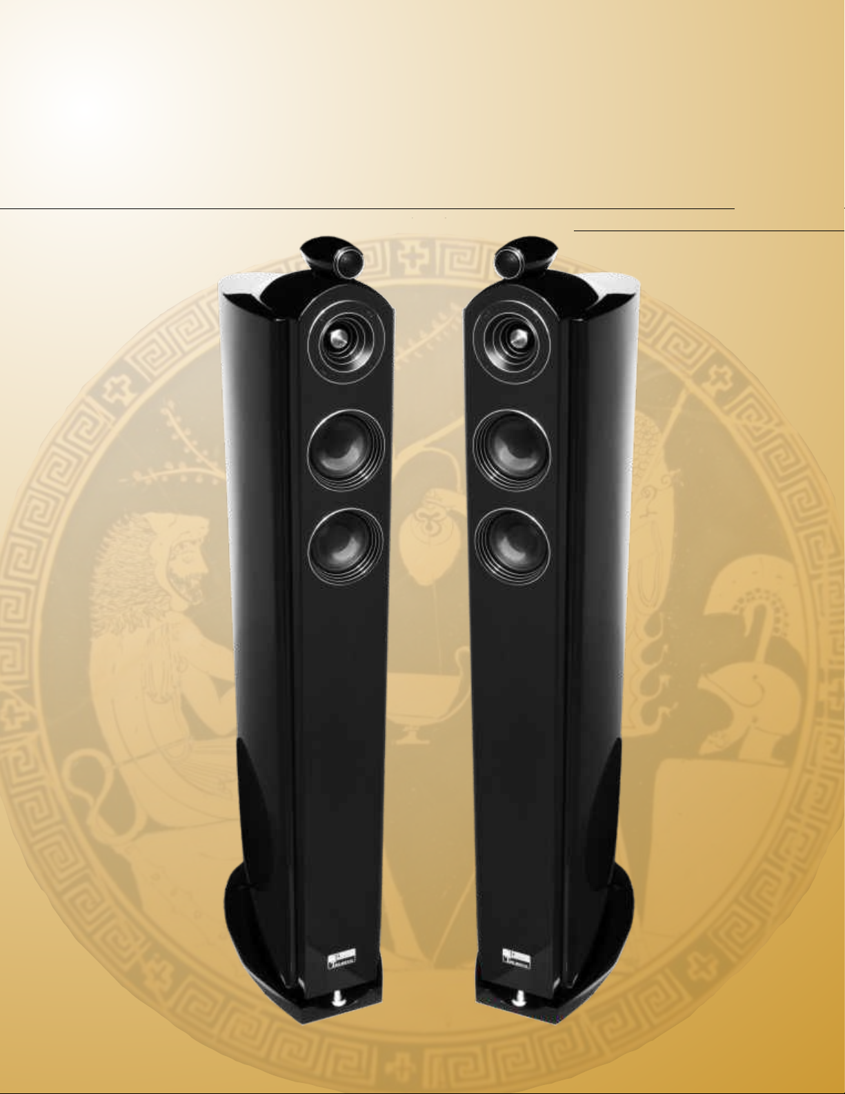
Telesto Design
arthquake Sound presents its next creation from allows the sound to travel in tubular shaped spheres.
the TITAN series, the Telesto towers.
E
In an array type design, SPL losses due to the distance
Their sleek, slim exteriors are matched only by their
performance. The main Telesto cabinets are built
from multi-laminations of steam bent, high density
fiber board. These laminations offer extreme rigidity
as well as lower cabinet vibrations. These single
pieces of egg shaped walls offer minimum wall
reflections and allow the cabinets to be transparent,
dynamic, and neutral.
To maximize floor coupling in low frequencies, the
Telestos are equipped with XLT EQ8 extra long
excursion subwoofers that create tight, fast, and
accurate low frequency extension. The EQ8’s are
mounted 90º off-axis from the front of the speakers.
This allows for a slim profile while delivering massive
bass response. With a name like Earthquake,
audiophiles tend to expect more, and the Telesto
delivers.
The mid-band of the Telestos are equipped with an
array of type loaded two 4” Kevlar drivers. The array
type design calls for identically designed stacked
speakers to play into the room. The array shares the
three dimensional space in front of the speakers, this
between the speakers and the listeners are 4 times lower
than conventional design. The dual carbon fiber drivers
are fast, neutral, and voice tuned.
The Telestos are crowned with two conically shaped
epoxy cabinets that harbor the T1 tweeter and the M2
midrange. The T1 and M2 are placed at about 3 feet
elevation from the base. This allows the speaker to
produce linear response that is not obstructed by furniture
and that is more direct to a sitting listener. The M2 is a
1.25” super midrange that delivers upper mids, and the T1
is a 1” silk dome with a Neo motor structure.
The design of the T1 tweeter module on top of the cabinet
in a separate enclosure achieves perfect positioning for
wider dispersion and better image stability. The T1 is
tuned to allow correct phase integration with M2, the
midrange driver. The enclosure designs are optimized to
deliver the ultimate in sound quality. Each Telesto is voice
tuned to deliver a transparent performance.
As AV front speakers or a conventional stereo system, the
Telestos will deliver a benchmark in performance and
style that is unprecedented.
Telesto Driver Units
T1: 1” silk dome, NEO super tweeter.
Frequency range: 3KHz-35KHz.
Fo=2.1KHz.
M2: 1.25” silk dome, compression tweeter,
phase correction, horn loaded.
Frequency range: 1.4KHz-10KHz.
Fo=1.25KHz.
M4: Dual 4” Kevlar midrange, Long
Excursion.
Frequency range: 100Hz-2KHz.
Fo=130Hz.
EQ-8 XLT: fiberglass cone midbass,
8” black fiberglass cone side woofer.
Frequency range: 30Hz-150Hz.
Fo=28Hz.
Telesto Manual 5
Earthquake Sound Corp. | (800) 576-7944 | www.earthquakesound.com
Page 7

Room Setup Options
LEFT
RIGHT
(Side Subwoofers face outwards, toward the wall.)
0°
LEFT
Specifications are subject to change without notice.
0°
RIGHT
= Subwoofer Sound Wave
= Speaker Sound Wave
Telesto Manual 6
Page 8

Amplifier Set-up Options
Single Amp. Option
For one Amplifier/Power Source per
system or per tower, leave gold
bridging bars on. Connect to the
Amplifier/Power Source from either
the high or the low terminals.
Power:
Impedance:
Frequency Response:
S/N:
HI
LO
back view
500W
4 Ohm
25Hz-40kHz
88dB/1m/2.83VSensitivity:
Bi-Amp. Option
The Telesto is designed to accept
two separate Amplifier/Power
Sources. For a Bi-Amplifier option,
take off gold bridging bars by
unscrewing terminals. Connect the
terminals to Amplifiers as shown
below. Be sure to tighten terminals
after bridging bars are off.
Amplifier/
Power Source
EARTHQUAKE SOUND U.S.A
www.earthquakesound.com
Power:
Impedance:
Frequency Response:
S/N:
HI
25Hz-40kHz
88dB/1m/2.83VSensitivity:
500W
4 Ohm
Amplifier/
Power Source
LO
EARTHQUAKE SOUND U.S.A
www.earthquakesound.com
Earthquake Sound Corp. | (800) 576-7944 | www.earthquakesound.com
Page 9

Telesto Dimensions and Specifications
front view
7.7”/195mm
44.7”/1135mm
50.5”/1282mm
4.25”/108mm
5.7”/145mm
5.4”/138mm
side view
15.9”/403mm
44.7”/1135mm
back view
19.7”/500mm
top view
18.3”/465mm
10.6”/270mm
18.3”/465mm
Telesto Specifications
Frequency:
Nominal Impedance:
Crossover frequency:
Recommended amplifier power:
Dimensions
Height:
Width:
Depth:
Net weight:
Available finish:
1.7”/44mm
1.7”/44mm
25Hz-40kHz
94dB+/-3dBSensitivity:
4 Ohms
350Hz, 3.2kHz, 10kHz
100WRMS and up to 500WRMS
50.5in/1282mm
7.7in/195mm
18.3in/465mm
31kgs/68.3lbs
Fine high gloss 3mm black lacquer paint
Specifications are subject to change without notice.
Telesto Manual 8 Telesto Manual 7
Page 10

5 Year Warranty Information
Page 11

Notes: _____________________________________________________________________________________
___________________________________________________________________________________________
___________________________________________________________________________________________
___________________________________________________________________________________________
___________________________________________________________________________________________
___________________________________________________________________________________________
___________________________________________________________________________________________
___________________________________________________________________________________________
FOR YOUR RECORDS:
Date of Puchase:
Authorized Dealer/Installer Name:
Dealer/Installer’s address:
Dealer/Installer’s phone number:
Serial number:
__________________________________
__________________________________
__________________________________
__________________________________
__________________________________
Page 12

Sound That Will Move You
Earthquake Sound reserves the right to amend details of the specifications without notice.
© Copyright Earthquake Sound Corporation
Earthquake Sound Corporation
2727 McCone Avenue. Hayward CA, 94545
Phone: 510-732-1000 Fax: 510-732-1095
 Loading...