

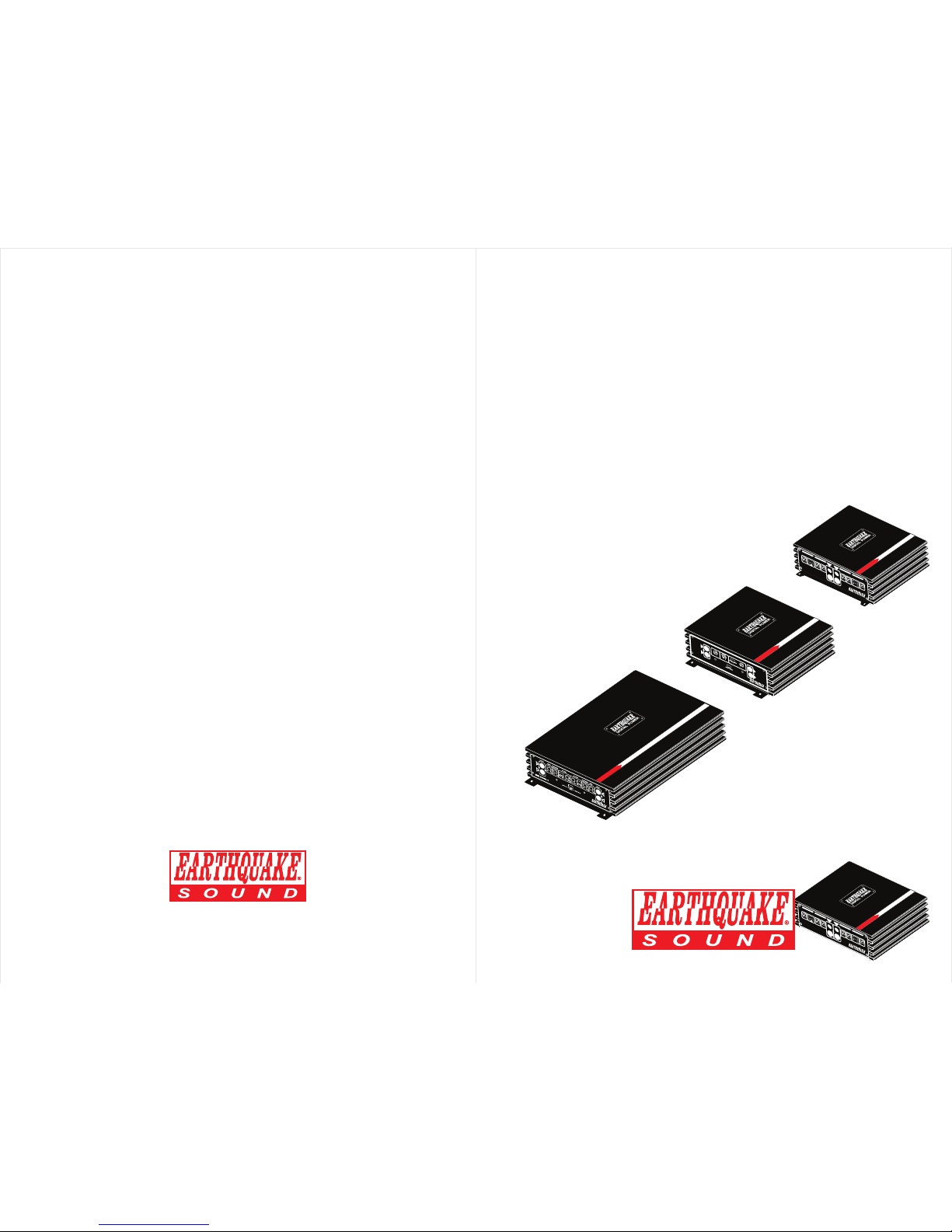
EarthQuake MiNi D1000.4, MiNi D1500.2, MiNi D3000.4 Installation Manual
1000 WATT CLASS D AMPLIFIER
MiNi D1000.4
MiNi D
1
000.4
BOOST
X-OVER
REAR
REAR
FRONT
FRONT
POWER
FREQ
GAIN
R
L
R
L
40Hz
400Hz
MIN
0dB
12dB
X-OVER
BOOST
0dB
12dB
LPF
LPF
HPF
HPF
FLAT
FLA
T
MAX
FREQ
40Hz
400Hz
GAIN
MIN
MAX
IN
IN
1500 WATT CLASS D AMPLIFIER
MiNi D1500.2
MiNi D
1
5
00.2
INPUT
OUTPUT
LEVEL
SUBSONIC
10V
15Hz
AUTO ON
REMOTE ON
RESET
0.2V
30Hz
X-OVER
20Hz
LPF
HPF
FLA
T
500Hz
R
R
L
L
3000 WATT CLASS D AMPLIFIER
MiNi D3000.4
MiNi
D3000.4
MiNi D1500.2
1000 WATT CLASS D AMPLIFIER
MiNi D1000.4
MiNi D
1
000.4
BOOST
X-OVER
REAR
REAR
FRONT
FRONT
POWER
FREQ
GAIN
R
L
R
L
40Hz
400Hz
MIN
0dB
12dB
X-OVER
BOOST
0dB
12dB
LPF
LPF
HPF
HPF
FLAT
FLAT
MAX
FREQ
40Hz
400Hz
GAIN
MIN
MAX
IN
IN
MiNi D1000.4
Earthquake Sound reserves the right to amend the details of the specifications without notice.
© Copyright Earthquake Sound Corporation
Earthquake Sound Corporation • 2727 McCone Avenue. Hayward, CA 94545. USA
www.earthquakesound.com
MiNi D Stereo Amplifiers
INSTALLATION MANUAL
The Sound That Will Move You
The Sound That Will Move You
FUSE
+
+
+
+
GND
REM
+12V
BRIDGED
RR RL
FLFR
(4-Ohms)
MiNi D
1000.4
BOOST
X-OVER
REAR
REAR
FRONT
FRONT
POWER
FREQ
GAIN
RLR
L
40Hz 400Hz
MIN
0dB
12dB
X-OVER
BOOST
0dB
12dB
LPF
LPF
HPF
HPF
FLATFLAT
MAX
FREQ
40Hz 400Hz
GAIN
MIN MAX
IN IN
FLAT
MiNi D
1500.2
INPUT
OUTPUT
LEVEL
SUBSONIC
10V 15Hz
AUTO ON REMOTE ON
RESET
0.2V 30Hz
X-OVER
20Hz
LPF HPF
FLAT 500Hz
R
R
L L
PWR
PROT
SPEAKER
FUSE
GND REM
+12V
– BRIDGE +
– L + – R +
. . . . . .
. . . . . .
2
3
www.earthquakesound.com
Specifications are subject to change without notice
Thank you for choosing Earthquake Sound’s line of MiNi D amplifiers, the best way
to enhance your factory mobile audio system. With proper installation and
responsible listening, your amplifier(s) will give you years of near perfect sound
reproduction.
We strongly recommend you to have your new amplifier(s) installed by an
authorized Earthquake Sound dealer. Installation professionals employed by your
dealer have the correct tools and knowledge to install your amplifier(s) neatly and
successfully. Also, when your new products are installed by an authorized dealer,
your products will include a ONE (1) YEAR LIMITED WARRANTY. If you choose to
perform your own installation, your warranty will be subject to further limitations.
Dealer policies on handling warranty requests may vary from one dealer to the next.
Please read the warranty information (located at the end of this booklet) in its
entirety and use good judgement when making these vital decisions.
THANK YOUTABLE OF CONTENTS
Cautions and Advisories .....................................
Our Thank You.....................................................
Features and Functions......................................
Signal Sensing - Auto On/Remote On................
Wiring Preparation..............................................
Wiring Configurations.........................................
Specifications.....................................................
One (1) Year Warranty Guidelines........................
2
3
4 - 5
6 - 7
8
9 - 11
12 - 13
14 - 15
CAUTION:
Earthquake amplifiers are capable of generating high sound pressure levels. You
should exercise caution when operating these amplifier systems. Long term
exposures to high levels of sound pressure will cause permanent damage to your hearing. Sound
pressure levels exceeding 85dB can be dangerous with constant exposure. Set your audio system
to a comfortable loudness level. Earthquake Sound Corporation does not assume liability for
damages resulting from the direct use of Earthquake amplifiers or other Earthquake products and
urges users to play their music at moderate listening levels.
DURATION PER DAY (HOURS)
8
6
4
3
2
1 - 1 1/2
1
1/2
1/4 OR LESS
SOUND LEVEL dBA
90
92
95
97
100
102
105
110
115
TH IS CH AR T S HOW S TH E U. S.
GO VER NM EN T’S O CCU PATI O NAL
SAFETY AND HEALTH ADMINISTRATION
(OSHA) REGULATIONS WHICH WERE IN
EF F ECT AT TH E T I ME OF TH I S
PU BLI CATI ON F OR PE RMISS I BL E
NOISE EXPOSURE, PER 29CFR1910.95,
TABLE G-16
PWR
PROT
FUSE
. . . . . .
. . . . . .
GND
REM
+12V
+ BRIDGE –
+
+
RL RR
+
+
FRFL
4
www.earthquakesound.com
Specifications are subject to change without notice
5
MiNi FUNCTIONS AND FEATURESD Stereo AmpsMiNi FUNCTIONS AND FEATURESD Stereo Amps
10
11 12113 1514
PWR
PROT
SPEAKER
FUSE
GND REM
+12V
– BRIDGE +
– L + – R +
. . . . . .
. . . . . .
PWR
PROT
FUSE
. . . . . .
. . . . . .
GND
REM
+12V
+ BRIDGE –
+
+
RL RR
+
+
FRFL
FUSE
+
+
+
+
GND
REM
+12V
BRIDGED
RR RL
FLFR
(4-Ohms)
10
11121314
MiNi D
1000.4
BOOST
X-OVER
REAR
REAR
FRONT
FRONT
POWER
FREQ
GAIN
RLR
L
40Hz 400Hz
MIN
0dB
12dB
X-OVER
BOOST
0dB
12dB
LPF
LPF
HPF
HPF
FLATFLAT
MAX
FREQ
40Hz 400Hz
GAIN
MIN MAX
IN IN
FLAT
MiNi D
1500.2
INPUT
OUTPUT
LEVEL
SUBSONIC
10V 15Hz
AUTO ON REMOTE ON
RESET
0.2V 30Hz
X-OVER
20Hz
LPF HPF
FLAT 500Hz
R
R
L L
9
7
8
6
5
2
3
3 3
4
4
1
1
5
2
6
4
9
3
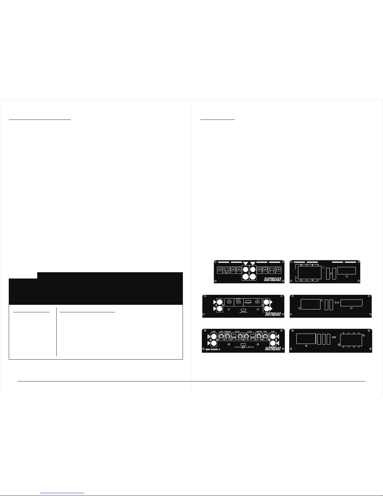
POWER LED: When lit up, the amplifier is functioning properly.
GAIN CONTROL: Available only on the D1000.4, set based on the head unit’s
output voltage. Note, this is not a volume control. Always start at the MIN
and slowly increase the gain. Stop as soon as distortion is heard then lower
the gain until the distortion disappear and only clear sound is produced.
RCA INPUT: Low level input of the D1000.4 is 0.2V to 5V RMS while the
D1500.2 & D3000.4 is 0.2V to 10V RMS. Be sure to use a HIGH LOW
LEVEL adaptor if the head unit has only speaker output.
XOVER SWITCH & FREQUENCY ADJUST: Used to adjust the boosted center
frequency.
BASS BOOST: Available only on the D1000.4, used to add 0 - 12dB to the
chosen center frequency.
LINE LEVEL CONTROL: Available only on the D1500.2 & D3000.4 with a
range of 0.2V to 10V RMS.
SUBSONIC FILTER: Available only on the D1500.2 & D3000.4, used to protect
the speakers from harmful low frequencies and DC Voltage. Note that the
subsonic filter only takes effect when the amplifier is in full range mode.
SIGNAL SENSING SWITCH: Available only on the D1500.2 & D3000.4.
Please refer to page 6-7 for the explanation of this feature.
RCA OUTPUT: Available only on the D1500.2.
7
8
10
12
14
13
15
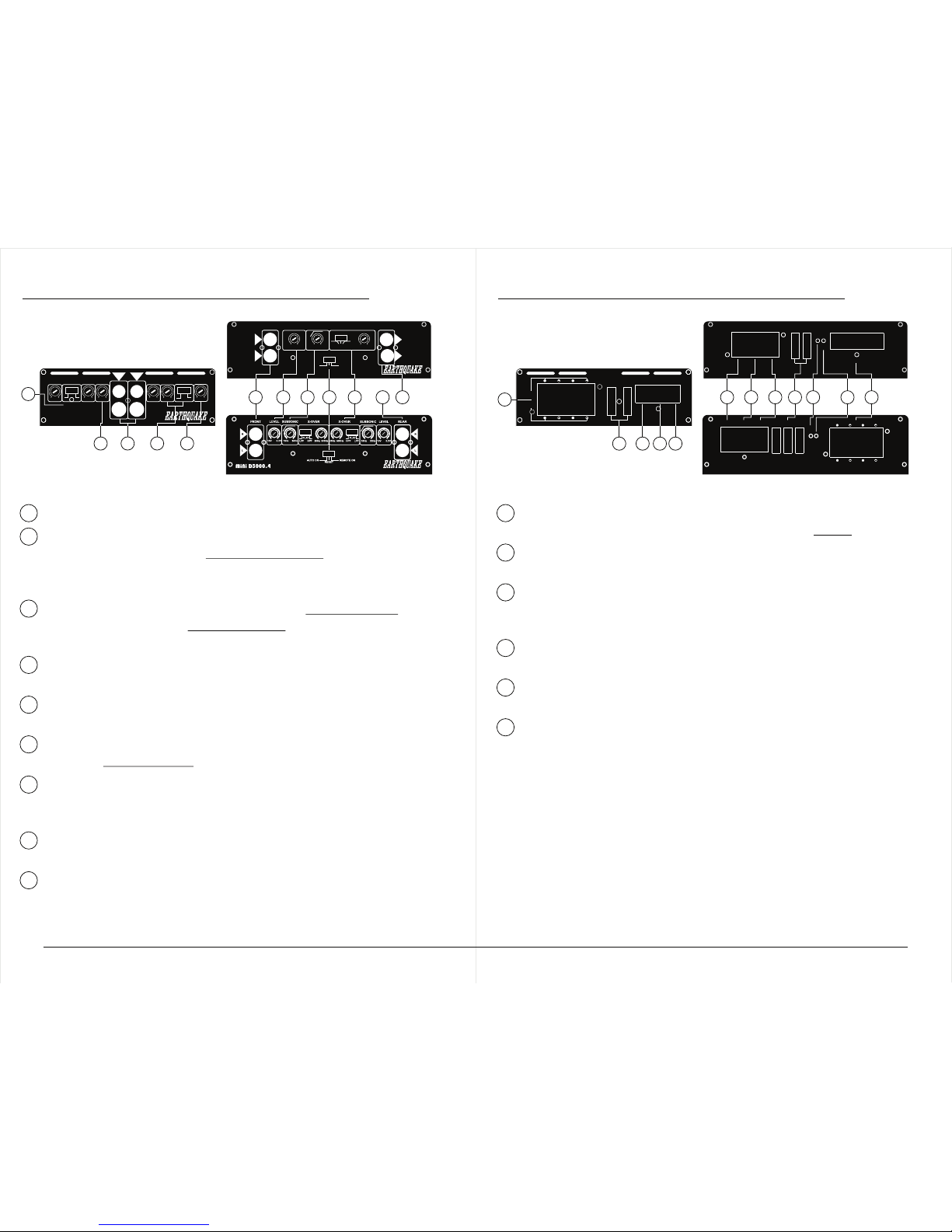
SPEAKER CONNECTION: Each amplifier has bridgeable speaker outputs.
Note that the minimum impedance in bridged mode is 4-Ohm.
GROUND TERMINAL: Connect to vehicle’s chassis/ground using a short 4
gauge cable (2 feet maximum in length).
REMOTE TERMINAL: Connect remote cable to the head unit’s remote
terminal. If multiple amplifiers are installed in the same system, additional
relays may be necessary.
+12V BATTERY TERMINAL: Connect to battery positive (+) using a 4 gauge
cable.
FUSES: Used as an added protection from damaging excessive current. Be
sure to use the proper fuse rating in your installation (see page 12).
PROTECTION LED: Available only on the D1500.2 & D3000.4. When lit up
upon powering on, the amplifier may be in self-test mode. If this LED stays
on, shut down the amplifier and locate what may have triggered the amplifier
to protection mode. If problem persists, call or e-mail our technical support
team for further assistance.
NOTE: Be sure to follow the wiring preparations/guidelines as listed on the next
page to ensure proper installation.
11
 Loading...