

Page 1
GAS/OIL
RATIO
50:1
Operator’s Manual
Original Operating Instructions
Manuel de l’utilisateur
Manual del operador
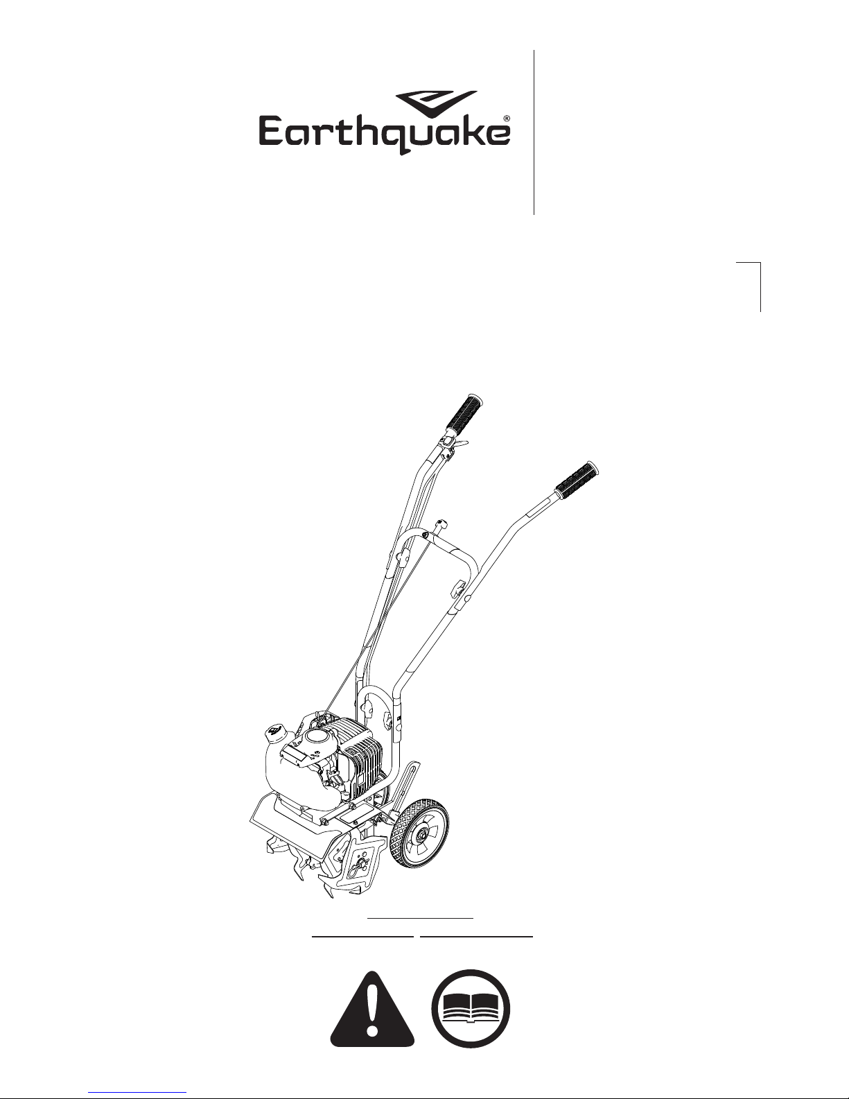
MC440
4-Cycle Cultivator
Motobineuse 4 temps
Cultivador de 4 ciclos
SN
Get parts online at
Pièces détachées en ligne à
Obtenga piezas en línea en
www.GetEarthquake.com
Includes Model:
Inclut le modèle, Incluye el modelo
12802
P/N: 23437
ECN: 11480
REV2: 01/10/17
© 2017 Ardisam, Inc.
All Rights Reserved
Tous droits réservés
Todos los derechos reservados
Page 2
Operator's Manual
NUMBER
MC440 4-Cycle Cultivator
INTRODUCTION
Congratulations on your investment in quality. Thank you for purchasing a 4-cycle cultivator from Earthquake®. We have worked
to ensure that this cultivator meets the highest standards for usability and durability. With proper care, your cultivator will provide
many years of service.
Please read this entire manual before installation and use. Earthquake reserves the right to change, alter or improve the
product and this document at any time without prior notice.
CONTENTS
Registration ........................................................................................................................................................................................................................................2
Warnings and Safety Precautions ...........................................................................................................................................................................................3-7
Features/Specifications ..................................................................................................................................................................................................................8
Unpacking and Assembly .............................................................................................................................................................................................................9
Operation ......................................................................................................................................................................................................................................9-13
Maintenance & Storage ......................................................................................................................................................................................................... 13-15
Troubleshooting and Repair ................................................................................................................................................................................................15-16
Parts Breakdown ...................................................................................................................................................................................................................... 17-21
15073 Border-Edger Kit Installation.........................................................................................................................................................................................22
DK43 Dethatcher Kit Installation ..............................................................................................................................................................................................23
Warranty ............................................................................................................................................................................................................................................24
FEDERAL EMISSIONS INFORMATION
Earthquake warrants to the retail purchaser, that this small, off-road engine was designed, built and equipped to conform at the
time of initial sale to all applicable regulations of the U.S. Environmental Protection Agency (EPA).
REGISTRATION AND SERVICE
Record the engine model number and serial number in the space provided for easy reference
when ordering parts or requesting technical support. Excluding emissions-related warranty
items, the warranty is valid only if the completed registration is received by Ardisam within 30
days of purchase. (SEE WARRANTY SECTION FOR MORE INFORMATION.) You can register
your warranty online by visiting www.getearthquake.com, or by mailing it to: Ardisam, 1160
Eighth Avenue, Cumberland, WI 54829. If you do not have a computer, call our customer service
department at (800) 345-6007 Mondays through Fridays from 8 a.m. to 5 p.m. CST.
OWNERSHIP RECORDS
Owner’s Name:
Owner’s Address:
City: State/Province: Zip Code/Postal Code:
Model Number: Serial Number:
Date of Purchase:
Notes:
SERIAL
DECAL
This manual may contain information for several models. Read and keep this manual for future reference. This manual contains important
information on SAFETY, ASSEMBLY, OPERATION, AND MAINTENANCE. The owner must be certain that all the product information is
included with the unit. This information includes the MANUAL, the REPLACEMENT PARTS and the WARRANTIES. This information must be
included to make sure state laws and other laws are followed. This manual should remain with the product even if it is resold.
2
Check for parts online at www.getearthquake.com or call 800-345-6007 M-F 8-5
Page 3
Operator's Manual
MC440 4-Cycle Cultivator
WARNINGS AND SAFETY PRECAUTIONS
OWNER’S RESPONSIBILITY
Accurate assembly and safe and effective use of the machine is
the owner’s responsibility.
• Read and follow all safety instructions.
• Carefully follow all assembly instructions.
• Maintain the machine according to directions and schedule
included in this Earthquake operator’s manual.
• Ensure that anyone who uses the machine is familiar with all
controls and safety precautions.
SPECIAL MESSAGES
Your manual contains special messages to bring attention to
potential safety concerns, machine damage as well as helpful
operating and servicing information. Please read all the
information carefully to avoid injury and machine damage.
NOTE: General information is given throughout the manual
that may help the operator in the operation or service of the
machine.
This symbol points out important safety
instructions which if not followed could endanger
your personal safety. Read and follow all
instructions in this manual before attempting to
operate this equipment.
BEFORE OPERATING ENGINE:
NOTICE
NOTICE INDICATES YOUR EQUIPMENT CAN BE DAMAGED
IF THE SAFETY INSTRUCTIONS THAT FOLLOW THIS SIGNAL
WORD ARE NOT OBEYED.
CAUTION
CAUTION INDICATES A HAZARD WHICH, IF NOT AVOIDED,
COULD RESULT IN PERSONAL INJURY AND/OR PROPERTY
DAMAGE.
WARNING
WARNING INDICATES A HAZARD WHICH, IF NOT AVOIDED,
COULD RESULT IN DEATH OR SERIOUS INJURY AND/OR
PROPERTY DAMAGE.
DANGER
DANGER INDICATES A HAZARD WHICH, IF NOT AVOIDED,
WILL CERTAINLY RESULT IN DEATH OR SERIOUS INJURY
AND/OR PROPERTY DAMAGE.
IMPORTANT
IMPORTANT INDICATES HELPFUL INFORMATION FOR
PROPER ASSEMBLY, OPERATION, OR MAINTENANCE OF
YOUR EQUIPMENT.
Please read this section carefully. Read entire operating and
maintenance instructions for this product. Failure to follow
instructions could result in serious injury or death. Operate the
machine according to the safety instructions outlined here and
inserted throughout the text. Anyone who uses this machine
must read the instructions and be familiar with the controls.
WARNING
CALIFORNIA PROPOSITION 65 WARNING
ENGINE EXHAUST FROM THIS PRODUCT CONTAINS
CHEMICALS KNOWN TO THE STATE OF CALIFORNIA
TO CAUSE CANCER, BIRTH DEFECTS, OR OTHER
REPRODUCTIVE HARM.
Intended Use / Foreseeable Misuse
IMPORTANT: This is a motorized rotary cultivator that works the
soil by means of rotating tines. It is pedestrian-controlled, but
not self-propelled, with a gasoline-fueled internal combustion
engine to power the tines. It shall not be used for any other
purpose.
DANGER
Check for parts online at www.getearthquake.com or call 800-345-6007 M-F 8-5 3
WARNING
YOU MUST READ, UNDERSTAND AND COMPLY WITH
ALL SAFETY AND OPERATING INSTRUCTIONS IN
THIS MANUAL BEFORE ATTEMPTING TO SETUP AND
OPERATE YOUR MACHINE.
FAILURE TO COMPLY WITH ALL SAFETY AND
OPERATING INSTRUCTIONS CAN RESULT IN LOSS OF
MACHINE CONTROL, SERIOUS PERSONAL INJURY TO
YOU AND/OR BYSTANDERS, AND RISK OF EQUIPMENT
AND PROPERTY DAMAGE. THE TRIANGLE IN THE TEXT
SIGNIFIES IMPORTANT CAUTIONS OR WARNINGS
WHICH MUST BE FOLLOWED.
Page 4

Operator's Manual
MC440 4-Cycle Cultivator
GENERAL SAFETY RULES
• Read, understand, and follow all instructions on the machine
and in the manual(s). Be thoroughly familiar with the controls
and the proper use of the machine before starting.
• Use this equipment for its intended purpose only.
• Familiarize yourself with all of the safety and operating
decals on this equipment and on any of its attachments or
accessories.
• Do not put hands or feet near or under rotating parts.
• Only allow responsible individuals who are familiar with the
instructions to operate the machine. Do not allow children
to operate this machine. Do not allow adults to operate the
machine without proper instruction.
• Thoroughly inspect the area where the machine is to be
used and remove all foreign objects. Your equipment can
propel small objects at high speed causing personal injury
or property damage. Stay away from breakable objects, such
as house windows, automobiles, greenhouses, etc.
• Wear appropriate clothing such as a long-sleeved shirt or
jacket. Also wear long trousers or slacks. Do not wear shorts.
Never wear sandals, sneakers or open shoes, and never
operate the machine with bare feet.
• Do not wear loose clothing or jewelry. They can get caught in
moving parts. Always keep hands, feet, hair and loose clothing
away from any moving parts on engine and machine.
• Always wear safety goggles or safety glasses with side shields
when operating the machine to protect your eyes from
foreign objects which can be thrown from the unit. Always
wear a protective hearing device.
• Always wear work gloves and sturdy footwear. Wear
footwear that will improve footing on slippery surfaces.
Leather work shoes or short boots work well for most people.
These will protect the operator’s ankles and shins from small
sticks, splinters, and other debris.
• It is advisable to wear protective headgear to prevent the
possibility of being struck by small flying particles, or being
struck by low hanging branches, twigs, or other objects
which may be unnoticed by the operator.
• Do not operate the machine without proper guards or other
safety protective devices in place.
• See manufacturer’s instructions for proper operation and
installation of accessories. Only use accessories approved
by the manufacturer.
• Operate only in daylight or good artificial light.
• Do not operate product when fatigued or under the
influence of alcohol, drugs or other medication which
can cause drowsiness or affect your ability to operate this
machine safely.
• Never operate machine in wet grass. Always be sure of your
footing; keep a firm hold on the handle and walk; never run.
• Watch for traffic when operating cultivator near, or when
crossing roads.
• If the equipment should start to vibrate abnormally, stop the
engine (motor), flip the ON/OFF switch to the OFF position.
Check immediately for cause. Vibration is generally a warning
of trouble. If the noise or vibrations of the machine increase,
stop immediately and perform an inspection.
• Never leave the machine unattended when the engine is
running. Flip the ON/OFF switch to the OFF position.
• Regularly inspect the machine. Make sure parts are not bent,
damaged or loose.
• Temperature of muffler and nearby areas may exceed 150°
F (65° C). Allow muffler and engine areas to cool before
touching. Never pick up or carry the machine while the
engine is running.
• Prolonged exposure to noise and vibration from gasoline enginepowered equipment should be avoided. Take intermittent
breaks and/or wear ear protection from engine noise as well as
heavy work gloves to reduce vibration in the hands.
• Keep all screws, nuts and bolts tight.
• Do not transport the machine from one place to another
with the engine running.
• When moving the packaged machine, always do so with a
partner.
• Check local regulations for age restrictions on use of this
machine.
PRODUCTSPECIFIC SAFETY RULES
• Do not cultivate above underground utilities, including water
lines, gas lines, electric cables, or pipes. Do not operate the
machine on terrain/soil with large rocks and foreign objects
which can damage the equipment.
• After striking a foreign object, stop the engine. Flip the ON/
OFF switch to the OFF position. Inspect the machine for
damage. If damaged, repair before starting and operating
the machine.
• The tines of the cultivator should not rotate when the engine
is idling. If it does rotate when engine is idling, contact
Earthquake customer service for instruction.
• If an object becomes lodged in the tines, flip the ON/OFF
switch to the OFF position, allow to cool before attempting
to remove the foreign object.
• The clutch will transfer maximum power after about two
hours of normal operation. During this break-in period clutch
slippage may occur. The clutch should be kept free of oil or
other moisture for efficient operation.
4
Check for parts online at www.getearthquake.com or call 800-345-6007 M-F 8-5
Page 5
Operator's Manual
MC440 4-Cycle Cultivator
DANGER
ENGINES GIVE OFF CARBON MONOXIDE, AN ODORLESS,
COLORLESS, POISONOUS GAS. CARBON MONOXIDE MAY
BE PRESENT EVEN IF YOU DO NOT SMELL OR SEE ANY
ENGINE EXHAUST. BREATHING CARBON MONOXIDE CAN
CAUSE NAUSEA, FAINTING OR DEATH, IN ADDITION TO
DROWSINESS, DIZZINESS AND CONFUSION.
IF YOU EXPERIENCE ANY OF THESE SYMPTOMS, SEEK
FRESH AIR AND MEDICAL ATTENTION IMMEDIATELY.
ENGINE SAFETY PRECAUTIONS
If your product comes with a separate engine manual, be
sure to read and follow all safety and warning precautions
outlined there, in addition to any in this manual.
Preventing Carbon Monoxide Poisoning
• Always start and run engine outdoors. Do not start or run
engine in an enclosed area, even if doors or windows are open.
• Never try to ventilate engine exhaust indoors. Carbon
monoxide can reach dangerous levels very quickly.
• Never run engine outdoors where exhaust fumes may be
pulled into a building.
• Never run engine outdoors in a poorly ventilated area where
the exhaust fumes may be trapped and not easily taken
away. (Examples include: in a large hole or areas where hills
surround your working area.)
• Never run engine in an enclosed or partially enclosed area.
(Examples include: buildings that are enclosed on one or
more sides, under tents, car ports or basements.)
• Always run the engine with the exhaust and muffler pointed
in the direction away from the operator.
• Never point the exhaust muffler towards anyone. People
should always be many feet away from the operation of the
engine and its attachments.
• Do not change the engine governor settings or over-speed
the engine.
Gasoline Fires and Handling Fuel Safely
Use extra care in handling gasoline and other fuels. They are
flammable and vapors are explosive.
CAUTION
HOT GASES ARE A NORMAL BYPRODUCT OF A
FUNCTIONING INTERNAL COMBUSTION ENGINE. FOLLOW
ALL SAFETY INSTRUCTIONS TO PREVENT BURNS AND
FIRES.
WARNING
NEVER ALTER OR MODIFY THE ENGINE FROM THE
FACTORY. SERIOUS INJURY OR DEATH MAY OCCUR IF
ENGINE IS MODIFIED OR ALTERED.
WHEN WORKING ON OR REPLACING PARTS FOR THE
ENGINE OR PRODUCT, YOU MUST ALWAYS FLIP THE ON/
OFF SWITCH TO THE OFF POSITION.
• Always fill fuel tank outside in a well ventilated area. Never
fill your fuel tank with fuel indoors. (Examples include:
basement, garage, barn, shed, house, porch, etc.) Never
fill tank near appliances with pilot lights, heaters, or other
ignition sources. If the fuel has to be drained, this should
be done outdoors. The drained fuel should be stored in a
container specifically designed for fuel storage or it should
be disposed of carefully.
• Never remove the fuel cap or add fuel with the engine
running. Stop engine and allow to cool before filling.
• Never drain fuel from engine in an enclosed area.
• Always wipe up excess (spilled) fuel from engine before
starting. Clean up spilled fuel immediately. If fuel is spilled,
do not start the engine but move product and fuel container
from area. Clean up spilled fuel and allow to evaporate and
dry after wiping and before starting.
• Allow fuel fumes/vapors to escape from the area before
starting engine.
• Test the fuel cap for proper installation before starting and
using engine.
• Always run the engine with fuel cap properly installed on
the engine.
• Never smoke while refilling engine fuel tank.
• Do not store engine with fuel in fuel tank indoors. Fuel and
fuel vapors are highly explosive.
• When storing extra fuel be sure that it is in an appropriate
container and away from any fire hazards.
• Prevent fire and explosion caused by static electric discharge.
Use only nonmetal, portable fuel containers approved by the
Underwriter’s Laboratory (U.L.) or the American Society for
Testing & Materials (ASTM).
Check for parts online at www.getearthquake.com or call 800-345-6007 M-F 8-5 5
Page 6
Operator's Manual
R
MC440 4-Cycle Cultivator
• Never siphon fuel by mouth to drain fuel tank.
• Always have an adult fill the fuel tank and never allow
children to fill the engine.
• Never allow an adult or anyone under the influence of drugs
or alcohol to fill engine.
• When storing gasoline or equipment with fuel in the tank,
store away from furnaces, stoves, water heaters or other
appliances that have a pilot light or other ignition source
because they can ignite gasoline vapors.
BURNS AND FIRES
The muffler, muffler guard and other parts of the engine become
extremely hot during the operation of the engine. These parts
remain extremely hot after the engine has stopped.
Prevention of Burns and Fires
• Never remove the muer guard from the engine.
• Never touch the muffler guard because it is extremely hot
and will cause severe burns.
• Never touch parts of the engine that become hot after
operation.
• Always keep materials and debris away from muffler guard
and other hot parts of the engine to avoid fires.
CHILDREN AND BYSTANDERS
Tragic accidents can occur if the operator is not alert to the
presence of children and/or bystanders. Never assume that
others will remain where you last saw them.
• Keep the area of operation clear of all persons, especially
small children and pets. Keep children under the watchful
care of a responsible adult.
• Be alert and turn machine off if children enter the area.
• Before and while moving backwards, look behind and down
for small children.
• Never allow children to operate the machine.
• Use extra care when approaching blind corners, shrubs, trees,
or other objects that may obscure vision.
SERVICE
• Always stop the engine whenever you leave the equipment,
before cleaning, repairing or inspecting the unit. Engine
should be turned off and cool. Never make adjustments or
repairs with the engine (motor) running. Flip the ON/OFF
switch to the OFF position to prevent accidental starting.
• Always wear eye protection when you make adjustments or
repairs.
• Keep all nuts and bolts tight and keep equipment in good
condition.
• Never tamper with safety devices. Check their proper
operation regularly.
• When servicing or repairing the machine, do not tip the
machine over or up unless specifically instructed to do so in
this manual. Service and repair procedures can be done with
the machine in an upright position. Some procedures will be
easier if the machine is lifted on a raised platform or working
surface.
• To reduce fire hazard, keep machine free of grass, leaves or
other debris build-up. Clean up oil or fuel spillage. Allow
machine to cool before storing.
• Stop and inspect the equipment if you strike an object.
Repair, if necessary, before restarting.
• Clean and replace safety and instruction decals as necessary.
• Inspect machine before storage. When not in use, flip the
ON/OFF switch to the OFF position and store indoors in a
dry place locked or otherwise inaccessible to children.
• Use only original equipment parts from Earthquake,
including all nuts and bolts.
NOTICE
THE RIGHT AND LEFT SIDES
OF YOUR CULTIVATOR ARE
DETERMINED FROM THE
OPERATING POSITION AS
YOU FACE THE DIRECTION OF
FORWARD TRAVEL.
L
6
Check for parts online at www.getearthquake.com or call 800-345-6007 M-F 8-5
Page 7
Operator's Manual
MC440 4-Cycle Cultivator
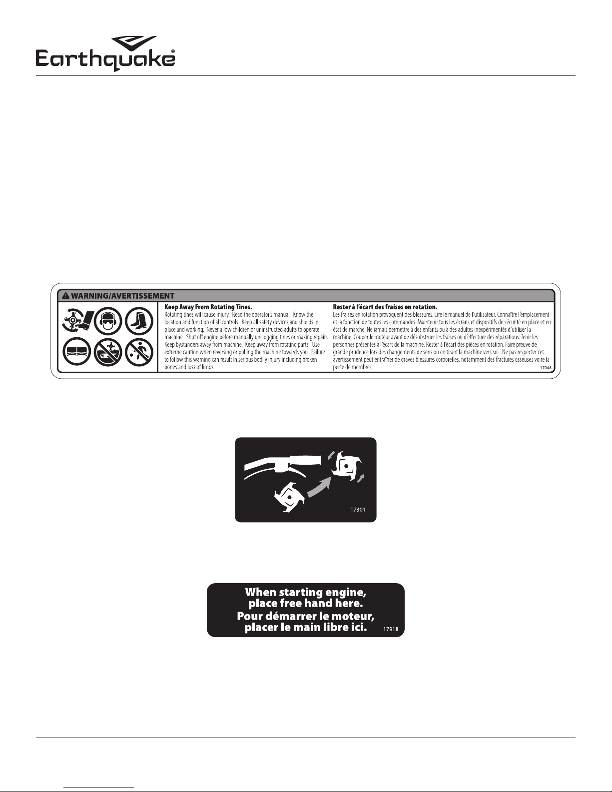
SAFETY DECALS
This cultivator has been designed and manufactured to provide you with the safety and reliability you would expect from an industry
leader in outdoor power equipment manufacturing.
Reading this manual and the safety instructions it contains will provide you with the necessary basic knowledge to operate this
equipment safely and effectively. We have placed a safety decal on the cultivator to remind you of some of this important information
while you are operating the unit.
These important safety decals are illustrated below, and are shown here to help familiarize you with the location and content of the
safety messages you will see as you perform normal cultivating operations. Please review these decals now, and if you have any
questions regarding its meaning or how to comply with these instructions, reread the complete safety instruction text in this manual.
Should a decal become unreadable because of being worn, faded, or otherwise damaged during the use of your cultivator, please
use the part number information provided to order a replacement label. Customers can order by calling Earthquake customer service.
These decals are easily applied, and will act as a constant visual reminder to you, and others who may use the equipment, to follow
the safety instructions necessary for safe, effective operation of your cultivator.
Part No. 17048
Cultivator Warning Decal - Tine Shield
Part No. 17301
Throttle Control Decal - Right Handlebar
Part No. 17918
Free Hand Safe Starting Location Decal - Left
Handlebar
Check for parts online at www.getearthquake.com or call 800-345-6007 M-F 8-5 7
Page 8
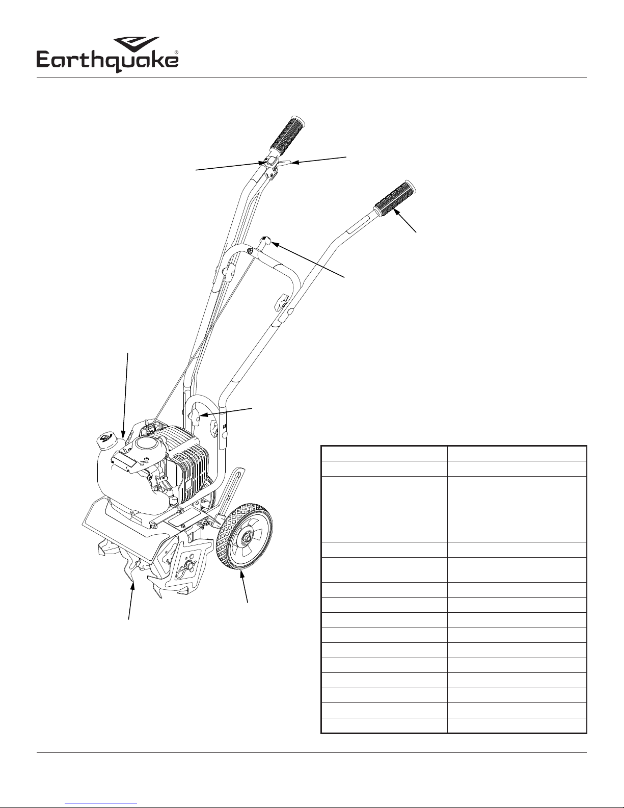
FEATURES
SEE THROUGH
FUEL TANK
HANDLEBAR
ON/OFF SWITCH
Operator's Manual
MC440 4-Cycle Cultivator
THROTTLE
CONTROL
LEVER
KNOBBY
COMFORT
GRIPS
EASY PULL-START
LOCATION
TOOL-LESS REVERSIBLE
& REPLACEABLE TINES
2 POSITION TOOL-LESS
HANDLEBAR HEIGHT
ADJUSTMENT
3 POSITION
TOOL-LESS
WHEEL HEIGHT
ADJUSTMENT
SPECIFICATIONS
ENGINE DISPLACEMENT 40cc
FUEL TANK CAPACITY 0.75 L
FUEL TYPE Minimum 87 octane gasoline with
low ethanol content
NOTE: If using an ethanol blended
fuel, a fuel stabilizer, mixed to
manufacturer specications, is
recommended
OIL TANK CAPACITY 3.72 -oz
OIL TYPE OIL VIPER 4 CYCLE (p/n 13235)
10W-30
SPARK PLUG NGK CMR6A
SPARK PLUG GAP 0.024 inch
TRANSMISSION Bronze gear drive
GEAR RATIO 32:1
TILLING WIDTH 6 inch min. - 10 inch max.
TILLING DEPTH 8 inch max.
TINE SPEED 288 rpm max.
WHEEL SIZE 7.0 inch dia. x 1.375 inch wide
WEIGHT OF UNIT 33 lb
ASSEMBLED SIZE 33.6 x 17.8 x 40.6 inch
8
Check for parts online at www.getearthquake.com or call 800-345-6007 M-F 8-5
Page 9
UNPACKING AND ASSEMBLY
UPPER RIGHT
UPPER LEFT
Operator's Manual
MC440 4-Cycle Cultivator
UNPACK CULTIVATOR
1. Carefully lift the cultivator out of the box, remove any packing
2. Find parts packet. Parts packet contains:
4 - T-Handle Nuts (4640)
4 - Curved Washers (4641)
4 - Saddle Bolts (4642)
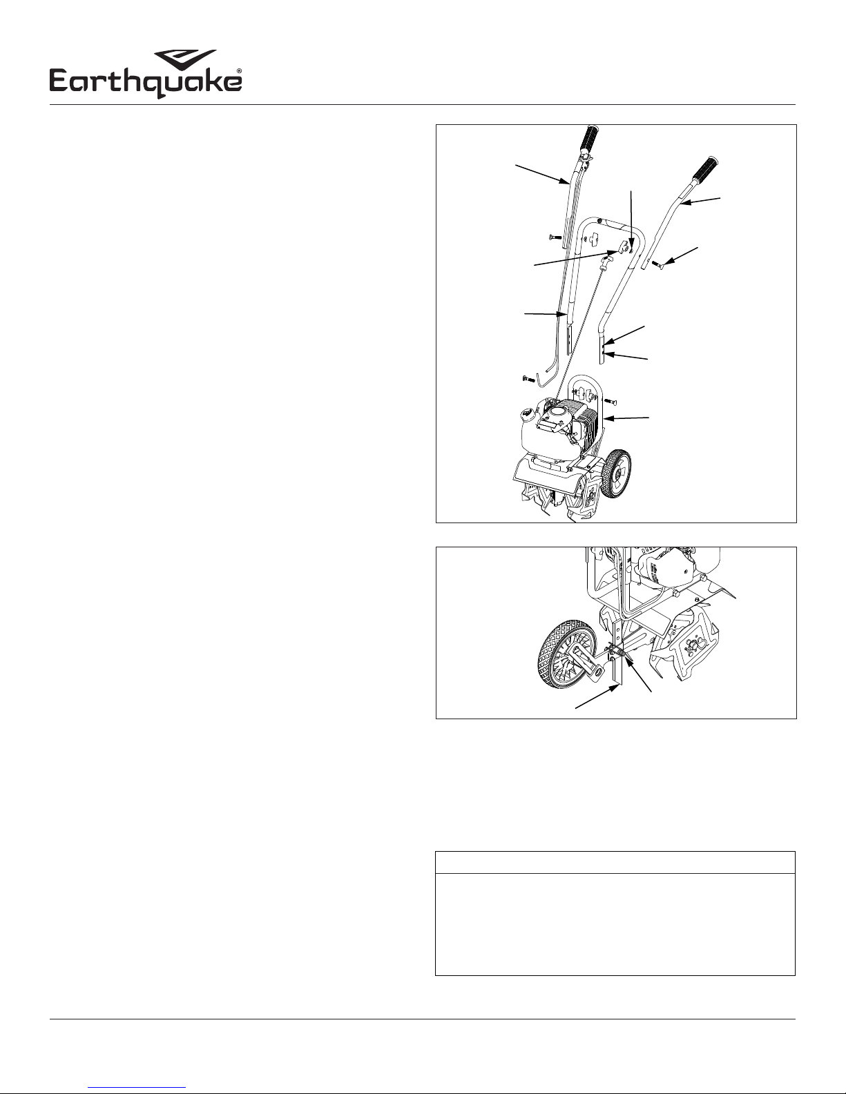
ASSEMBLY
1. Stand the cultivator assembly upright with tines and wheels
2. Using two T-handle nuts, two saddle bolts, and two curved
3. Attach the upper right and left handlebars to the middle
4. The drag stake is shipped with point facing upwards. Before
OPERATION
PREPARING ENGINE FOR STARTING
GAS AND OIL
NOTE:
engine oil before starting engine. If engine is started without oil,
engine may be damaged beyond repair and will not be covered
by warranty.
material and cut any ties holding the handlebar pieces to the
cultivator assembly.
on a level surface. Wheels should be set in the lowest position
(See page 12 for wheel adjustment instructions). DO NOT
place the cultivator on a high surface where it can fall and
cause property damage or personal injury.
washers, attach the middle handlebar to the lower handlebar
that is already connected to the cultivator assembly (SEE
FIGURE 1. Make sure the pull cord is in the center of the
middle handle bar when attaching. The middle handlebar
can be installed in one of two positions, one high and one
low. DO NOT overtighten the T-handle nuts.
handlebar using the two remaining T-handle nuts, saddle
bolts, and curved washers (SEE FIGURE 1. DO NOT
overtighten the T-handle nuts.
using, remove lock pin and turn the drag stake around so the
point is directed in the downward position facing towards
the tines. Re-insert lock pin. SEE FIGURE 2
Engine is shipped from factory without oil. You must add
HANDLEBAR
T-HANDLE NUT
MIDDLE
HANDLEBAR
FIGURE 1
DRAG STAKE
FIGURE 2
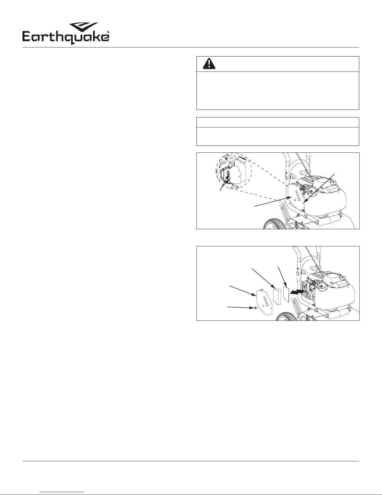
Checking and Adding Oil
Be sure the engine is located on a level surface before checking
or refilling oil. Proper position for checking oil level or refilling
oil is face down, with the gas tank of the cultivator down on a
horizontal surface. SEE FIGURE 3
CURVED
WASHER
HANDLEBAR
SADDLE BOLT
LOW POSITION
MOUNT HOLES
HIGH POSITION
MOUNT HOLES
LOWER
HANDLEBAR
LOCK PIN
NOTICE
Quality
To operate the engine, we recommend using VIPER brand 4-cycle
oil (13235), included with each new cultivator, or an equivalent
10W-30 engine oil to ensure that the engine operates correctly
throughout the life of the engine. Use straight unleaded
premium gasoline, low/no ethanol blends recommended.
Check for parts online at www.getearthquake.com or call 800-345-6007 M-F 8-5 9
ENGINE MUST BE TIPPED FORWARD WITH FUEL TANK
DOWN WHEN CHECKING OIL LEVEL OR FILLING WITH
OIL. FAILURE TO DO SO CAN RESULT IN OVERFILLING
THE ENGINE WITH OIL WHICH WILL IMPAIR THE ENGINE’S
PERFORMANCE. ONLY CHECK OIL AFTER LETTING
MACHINE SIT FOR FIVE MINUTES.
Page 10
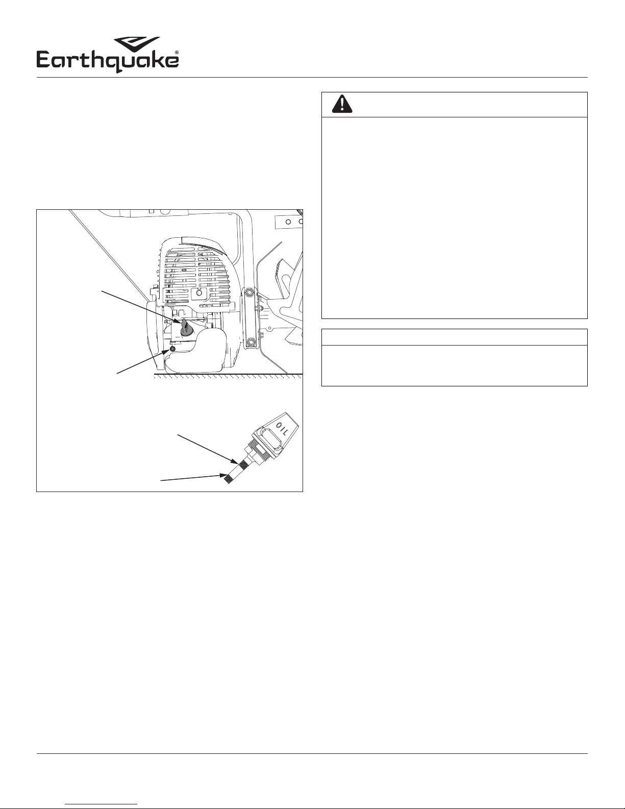
1. Clean around oil ll area.
2. Unscrew dipstick and wipe clean with cloth.
3. Reinsert dipstick (must be fully threaded for accurate reading).
4. Unscrew and check dipstick. If no oil shows on the dipstick,
refill so that the oil level appears between the low and high
marks on the dipstick. SEE FIGURE 3
Operator's Manual
MC440 4-Cycle Cultivator
DANGER
ENGINE IS SHIPPED FROM FACTORY WITHOUT OIL. YOU
MUST ADD ENGINE OIL BEFORE STARTING ENGINE.
IF ENGINE IS STARTED WITHOUT OIL, ENGINE MAY BE
DAMAGED BEYOND REPAIR AND WILL NOT BE COVERED BY
WARRANTY.
5. Change oil if contaminated.
OIL DIPSTICK
OIL DRAIN
SCREW
CULTIVATOR TIPPED FORWARD
ON LEVEL, HORIZONTAL SURFACE
HIGH OIL MARK
LOW OIL MARK
FIGURE 3
Filling Fuel Tank
1. Shut-o engine and allow engine to completely cool before
relling the fuel tank.
2. Move to a well ventilated area, outdoors, away from flames
and sparks.
3. Clean debris from area around the fuel cap.
4. Loosen fuel cap slowly. Prevent the cap from coming in
contact with dirt or debris.
5. Carefully add fuel without spilling.
6. Do not fill fuel tank completely full, allow space for fuel to
expand.
7. Immediately replace fuel cap and tighten. Wipe off spilled
fuel and allow to dry before starting engine.
NEVER STORE ENGINE WITH FUEL IN THE TANK INDOORS.
FUEL AND FUEL VAPORS ARE HIGHLY FLAMMABLE.
ONLY AN ADULT MUST ALWAYS HANDLE AND FILL THE
ENGINE WITH FUEL.
ALWAYS HANDLE GAS IN A WELL VENTILATED AREA,
OUTDOORS, AWAY FROM FLAMES OR SPARKS.
DO NOT START ENGINE IF FUEL IS SPILLED. WIPE OF
EXCESS FUEL AND ALLOW TO DRY. REMOVE ENGINE FROM
AREA TO AVOID SPARKS.
NOTICE
DO NOT SPRAY WATER ON OR NEAR THE ELECTRONICS OF
THE CULTIVATOR AS THIS MAY RESULT IN DAMAGE TO THE
ELECTRICAL COMPONENTS.
OPERATION TIPS
1. The clutch will transfer maximum power after about two
hours of normal operation. During this break-in period clutch
slippage may occur. The clutch should be kept free of oil and
other moisture for ecient operation.
2. Cultivate without placing excessive body weight on the unit.
The cultivator operates most eciently with the weight of the
unit itself.
3. Never run engine indoors. Exhaust fumes are deadly.
STARTING AND STOPPING ENGINE
• Move the engine to a well ventilated area, outdoors, to
prevent carbon monoxide poisoning.
• Move to an area away from flames or sparks, to avoid
ignition of vapors if present.
• Remove all debris from air cleaner holes and gas cap to
ensure proper air flow.
• If it is the first time starting the cultivator, make sure the
included 4-cycle oil has been poured into the oil fill area.
COLD ENGINE START:
Starting engine for first time or after engine has cooled off or
after running out of fuel.
10
Check for parts online at www.getearthquake.com or call 800-345-6007 M-F 8-5
Page 11
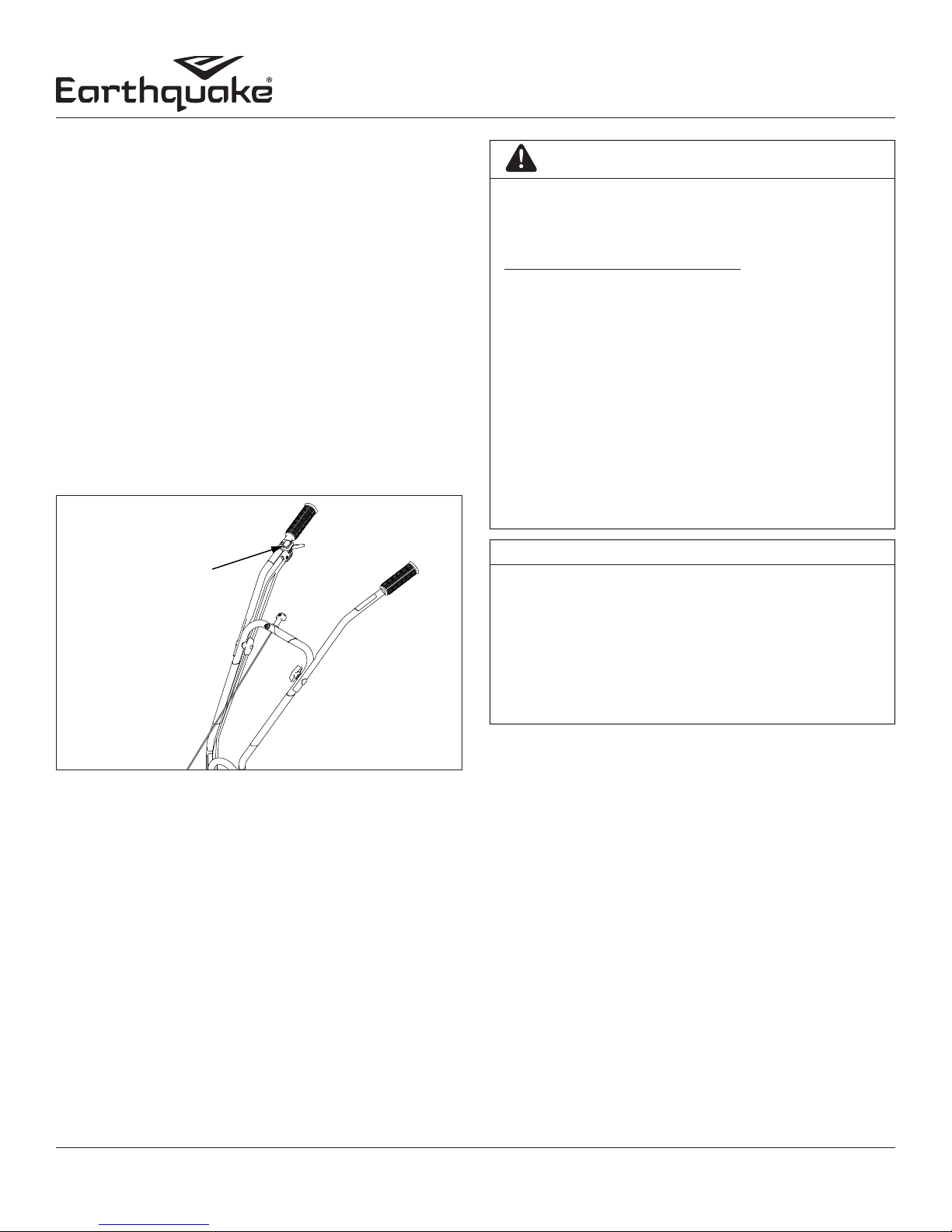
1. Move choke lever to CHOKE position. SEE FIGURE 4
NOTE: CHOKE position is defined by moving the choke
lever as far to the right, towards gas tank, as possible.
2. Prime unit until primer hose is filled with gas.
NOTE: When using the primer bulb, allow the bulb to
return completely to its original position between pushes.
3. Push ON/OFF switch to the ON position.
4. Hold handle bar firmly. Grasp starter handle and pull out
slowly until it pulls slightly harder. Without letting the starter
handle retract, pull rope with a rapid full arm stroke. Let it
return to its original position slowly. Repeat this step every
time the starter rope is pulled until unit fires or runs.
NOTE: If engine fails to start after 5-6 pulls, push primer 1
time and pull starter rope again.
5. After engine starts running, move choke lever to HALF
CHOKE position until unit runs smoothly.
NOTE: Half choke is defined when the choke lever is
between CHOKE and RUN positions. SEE FIGURE 4
6. Move choke lever to RUN position and squeeze throttle to
desired speed. SEE FIGURE 4
NOTE: Run at full throttle when possible. Do not let unit
idle for extended periods of time.
7. To stop engine, push ON/OFF switch to OFF position.
HOT/WARM ENGINE START:
1. Begin with Step 3 of Cold Engine Starting.
2. If engine does not fire, refer to Step 1 of Cold Engine Starting.
TO STOP ENGINE:
Push the ON/OFF switch to the OFF position.
DANGER
DO NOT ATTEMPT TO START ENGINE IN THE FOLLOWING
WAYS:
• DO NOT USE STARTING FLUID.
• DO NOT SPRAY FLAMMABLE LIQUIDS OR VAPORS
INTO AIR CLEANER, CARBURETOR, OR SPARK PLUG
CHAMBER.
Operator's Manual
MC440 4-Cycle Cultivator
CAUTION
MAKE SURE THE UNIT IS IN A STABLE POSITION BEFORE
PULLING THE STARTER HANDLE.
WHEN THE UNIT START TO FIRE OR RUN, RETURN BOTH
HANDS TO THE HANDLEBAR POSITION TO MAINTAIN
CONTROL AND STABILITY OF THE UNIT.
IF ENGINE FAILS TO START AFTER FOLLOWING STARTING
PROCEDURES, PLEASE CONTACT OUR CUSTOMER SERVICE
DEPARTMENT AT 8003456007.
STARTER ROPE CAN CAUSE AN UNANTICIPATED JERK
TOWARD ENGINE. PLEASE FOLLOW INSTRUCTIONS TO
AVOID INJURY.
NEVER LEAVE ENGINE RUNNING WHILE UNATTENDED.
TURN OFF AFTER EVERY USE.
NEVER CARRY CULTIVATOR FROM ONE LOCATION TO
ANOTHER WHILE ENGINE IS RUNNING.
ALWAYS WEAR A PROTECTIVE HEARING DEVICE.
DO NOT START ENGINE IF FUEL IS SPILLED. WIPE OFF
EXCESS FUEL AND ALLOW TO DRY.
K
E
O
H
C
N
U
R
FIGURE 4
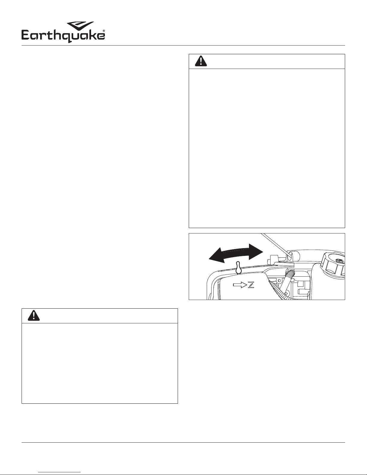
ADJUSTING WHEELS AND DRAG STAKE
The wheels on the cultivator can be adjusted to one of three
positions. The LOW wheel position is used for transporting the
cultivator across a smooth level surface while the engine is not
running. The HIGH and HIGHEST wheel positions are used when
cultivating in soil and help stabilize the unit when cultivating at
different depths. (SEE FIGURE 5
To adjust wheels up or down (SEE FIGURES 6 AND 7:
• DO NOT REMOVE SPARK PLUG AND ATTEMPT TO
START ENGINE. FLAMMABLE FUEL CAN SPRAY OUT &
IGNITE FROM A SPARK FROM SPARK PLUG.
Check for parts online at www.getearthquake.com or call 800-345-6007 M-F 8-5 11
1. Pull the locking metal sleeve against the spring, away from the
vertical guide until it releases from one of the three notched
positions in the vertical guide.
2. Slide the wheel set up or down to the desired position, and
release the locking metal sleeve until it locks into desired
notch in the vertical guide.
Page 12
Operator's Manual
MC440 4-Cycle Cultivator
The drag stake is used to help regulate cultivating depth and
control the cultivator from leaping forward during operation.
Resistance to forward motion is greatest when the drag stake is
set in its lowest position allowing for deeper cultivation.
To adjust the drag stake (SEE FIGURE 7:
1. Pull the lock pin out of the drag stake mount hole.
2. Position the drag stake so the pointed tip is directed
downward.
3. Insert the lock pin into the hole that achieves desired
depth.
HIGH
POSITION
MIDDLE
POSITION
LOW
POSITION
TINE REMOVAL AND INSTALLATION
To Remove Tines (SEE FIGURE 8)
1. Remove the hairpins from each end of the tine shaft.
2. Slide the four tines o the shaft.
To Install Tines
1. First slide the inside tines onto each end of the tine shaft.
One inside tine is stamped with a B and the other is
stamped with a C.
2. Slide the outside tine A and tine D onto each end of the
shaft next. The tines should be installed in the correct order
so that they are positioned left to right A, B, C, D, as viewed
from the user’s position on the MC440. Make sure that the
hub collars on both the right and left pairs of tines face
each other so that there is adequate spacing between the
tine blades. SEE FIGURE 8
3. Insert the hairpins into the holes at each end of the tine
shaft to lock the tines into place.
NOTE: Tines can be reversed so the pointed tip of the tines
are directed forward - for more aggressive digging. In this
arrangement, tines are positioned left to right D, C, B, A as
viewed from the user’s position
FIGURE 5
EXPANDED
SPRING
LOCKING METAL SLEEVE
(LOCKED POSITION)
FIGURE 6
DRAG STAKE
COMPRESSED
SPRING
LOCKING METAL SLEEVE
(UNLOCKED POSITION)
LOCK PIN
HUB
INNER
TINE
OUTER
TINE
COLLARS
HAIRPIN
TINE SHAFT
D
C
INNER HOLE
B
A
FIGURE 8
NOTE: To reduce cultivating width from 10” to 6”, remove
both outer tines and reinsert hairpins through the two inner
holes on the tine shaft to secure both inner tines in place.
*Scan this QR code with your smartphone
for helpful hints and tips for using your
cultivator. www.getearthquake.com
FIGURE 7
12
You may need to get a QR Code® reader from your
smartphone app store. Data rates may apply.
Check for parts online at www.getearthquake.com or call 800-345-6007 M-F 8-5
Page 13
MAINTENANCE AND STORAGE
STEPS FOR WORKING ON EQUIPMENT
1. Flip the ON/OFF switch to the OFF position. SEE FIGURE 9
2. Replace or repair the part on the cultivator.
3. Check all parts that were repaired, or removed during repair,
that they are secure and fit correctly.
NOTE: All repair parts must come from the factory. Never
replace parts that are not specifically designed for the
cultivator.
CULTIVATOR MAINTENANCE
1. Keep all screws, nuts, and bolts tight.
2. For cold weather operation, store the unit in a cool environment.
Transferring the unit from a cold to a warm place can cause the
build up of harmful condensation.
Operator's Manual
MC440 4-Cycle Cultivator
WARNING
PRACTICE SAFETY AT ALL TIMES. ENGINE MUST BE TURNED
OFF AND ALLOWED TO COOL BEFORE ATTEMPTING ANY
MAINTENANCE OR REPAIR.
TO PREVENT ACCIDENTAL STARTING:
• ENGINE MUST BE TURNED OFF AND COOL BEFORE
CHECK AND ADJUSTING ENGINE OR EQUIPMENT.
• TEMPERATURE OF MUFFLER AND NEARBY AREAS MAY
EXCEED 150° F 65° C. AVOID THESE AREAS.
• CHECK CULTIVATOR OFTEN FOR LOOSE NUTS AND
BOLTS. KEEP THESE ITEMS TIGHTENED.
• NEVER STORE ENGINE WITH FUEL IN THE TANK INSIDE
A BUILDING. POTENTIAL SPARKS MAY BE PRESENT
FOR IGNITION OF FUEL AND FUEL VAPORS.
• ONLY AN ADULT MUST DO MAINTENANCE AND REPAIR
ON ENGINE AND CULTIVATOR.
ON/OFF SWITCH
FIGURE 9
ENGINE MAINTENANCE
Refer to engine emission warranty included with your product
for maintenance schedule.
Good maintenance is essential for safe, economical, and troublefree operation. It will also help reduce air pollution. To help
you properly care for your engine, the following pages include
a maintenance schedule, routine inspection procedures, and
simple maintenance procedures using basic hand tools. Other
service tasks that are more difficult, or require special tools, are
best handled by professionals and are normally performed by a
technician or other qualified mechanic.
Maintenance, replacement or repair of the emissions control
devices and systems may be performed by any non-road
engine repair establishment or individuals. However, items
must be serviced by an authorized dealer to obtain “no charge”
emissions control warranty service.
NOTICE
PROPER POSITION FOR CHECKING OIL LEVEL OR
REFILLING OIL IS FACE DOWN, WITH THE FUEL TANK
OF THE CULTIVATOR DOWN ON A HORIZONTAL
SURFACE. SEE FIGURE 3 ON PAGE 10. FAILURE TO
MAINTAIN THIS POSITION CAN RESULT IN OVER
FILLING THE ENGINE WITH OIL WHICH WILL IMPAIR
THE ENGINE’S PERFORMANCE. ONLY CHECK OIL
AFTER LETTING MACHINE SIT FOR FIVE MINUTES.
LUBRICATION
Choose engine oil that meets or surpasses the latest API service
classification. For temperatures higher than 32º F, use 10W-30
motor oil. Use SAE 5W-30 if temperatures are below 32º F.
OIL MAINTENANCE
After the first five hours of operating a new Viper engine the
oil should be replaced, and every 50 hours of operating time
thereafter. The oil should be changed every 25 hours if used
under severe conditions, such as in high temperatures or under
heavy loads. Check oil periodically; do not overfill!
CHANGING OIL
Be sure the engine is not operating and is located on a level
surface before checking or refilling oil. Engine should be warm
for easy removal of oil.
STEPS FOR CHANGING OIL
1. Flip the ON/OFF switch to the OFF position.
Check for parts online at www.getearthquake.com or call 800-345-6007 M-F 8-5 13
Page 14
2. Unscrew oil drain screw and empty oil into suitable oil
container. (SEE FIGURE 3 on PAGE 10) Dispose of oil properly.
3. Reinsert drain screw and remove oil dipstick.
4. Fill with appropriate oil to “FULL“ or top line of dipstick (SEE
FIGURE 3 on page 10).
5. Reinsert dipstick or oil fill cap and tighten.
SPARK PLUG
The recommended spark plug is a NGK CMR6A. For
maintenance and care of the spark plug go online to www.
getearthquake.com for instructions or call Earthquake
customer service.
Operator's Manual
MC440 4-Cycle Cultivator
DANGER
TO AVOID INJURY OR DEATH, NEVER SIPHON FUEL BY
MOUTH.
NEVER STORE CULTIVATOR WITH FUEL IN THE FUEL TANK
INSIDE AN ENCLOSED AREA OR BUILDING.
NOTICE
NEVER TWIST AIR FILTERS WHEN CLEANING. ALWAYS
PRESS.
CARBURETOR
Never tamper with factory setting of the carburetor.
COOLING FINS
Cooling fins, air inlets and linkages must be free from any debris
before each use.
AIR FILTER
Never run engine without air cleaner properly installed. Added
wear and engine failure may occur if air cleaner is not installed
on engine.
Service air cleaner every 3 months or after 20 hours of operation.
Clean filter daily in extremely dusty conditions.
Steps for Replacing and Cleaning Air Filter
1. Before removing the air filter cover, move the choke lever to
the CHOKE position.
2. To remove air filter cover, unscrew the cover bolt with a screw
driver and gently pop out the front latch tab. The cover then
can be slid off the back latch tabs and away from the engine.
SEE FIGURE 10
3. Remove the foam filter and fiber filter elements. Replace with
a new fiber filter and a new oiled foam filter (SEE FIGURE 11),
or clean the original foam and fiber filters with warm water
and mild soap. Remember to thoroughly oil the foam filter
with 30 or 40 weight motor oil and squeeze out any excess oil
before reinstalling it. Make sure to press the foam filter evenly
into place over the fiber filter to ensure that the foam is fully
seated into its sealed position.
4. Replace the air filter cover by first connecting the back latch tabs
then swinging the cover, making sure the foam filter block stays
fully seated and in its proper position, and connect the front latch
tab so that it is secured into place.
5. Screw the cover bolt back into place. Check that the cover is
securely attached by pulling slightly on the cover. If the cover
doesn’t move when pulled, it is secure.
FRONT
LATCH TAB
BACK LATCH
TABS
AIR FILTER
COVER
FIGURE 10
FOAM FILTER
ELEMENT
AIR FILTER
COVER
COVER
BOLT
FIGURE 11
FIBER FILTER
ELEMENT
TRANSPORTING YOUR CULTIVATOR
1. After using the cultivator, and before transporting it in a truck
bed, check that the gas cap is screwed on (clockwise) tightly.
The gas cap will not leak during transporting if gas cap is tight.
Never transport engine inside an enclosed space within a
vehicle. Fuel or fuel vapors may ignite causing serious injury
or death.
2. If fuel is present in the fuel tank, transport in an open vehicle
in an upright position.
3. If an enclosed vehicle must be used, remove the fuel into an
approved red fuel container. DO NOT siphon by mouth.
4. Wipe away any spilled fuel from engine and cultivator. Allow
to dry.
5. Run the engine to use up the fuel in the carburetor and fuel
14
Check for parts online at www.getearthquake.com or call 800-345-6007 M-F 8-5
Page 15
Operator's Manual
MC440 4-Cycle Cultivator
tank. Always run engine in a well ventilated area.
6. Fuel cap should be screwed down tightly before transporting
your cultivator in a vehicle.
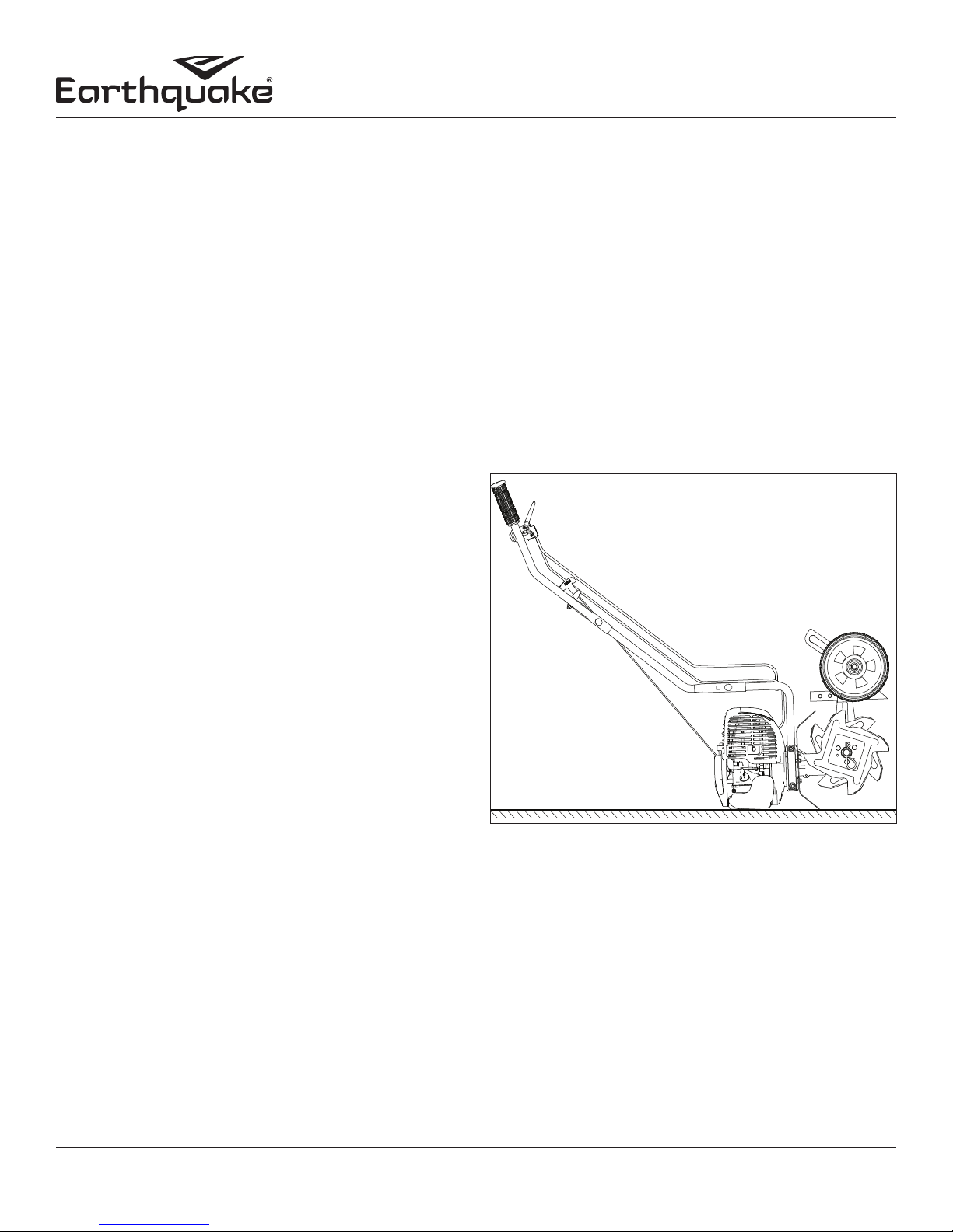
LONGTERM STORAGE
If your cultivator will not be used for more than one month,
prepare it for long-term storage.
Steps for Long-Term Storage
1. Mix an appropriate amount of fuel stabilizer to fresh gasoline,
in the ratio recommended on the stabilizer packaging.
Run the engine for five minutes to distribute the stabilizer
mixture throughout the fuel system. This will prevent gum,
varnish and corrosion build up in your fuel system during
long-term storage for up to 12 months.
2. Remove all debris from cultivator tines and engine.
3. Store cultivator by placing it on a level surface, resting on
the fuel tank and tine shield. SEE FIGURE 12
TROUBLESHOOTING AND REPAIR
At Earthquake, we build quality and durability into the design
of our products; but no amount of careful design by us, and
careful maintenance by you, can guarantee a repair-free life for
your Earthquake cultivator. Most repairs will be minor, and easily
fixed by following the suggestions in the troubleshooting guide
in this section.
The guide will help you pinpoint the causes of common problems
and identify remedies.
For more complicated repairs, you may want to rely on your
retailer, an authorized service center or Earthquake. Earthquake
will make the necessary repairs if a service center is not available.
A parts breakdown is located toward the end of this manual.
We will always be glad to answer any questions you have, or
help you find suitable assistance. To order parts or inquire about
warranty, call or e-mail us using the contact information found
in this section.
ORDERING REPLACEMENT PARTS
Parts can be obtained from the store where the cultivator was
purchased or direct from the factory. To order parts visit www.
getearthquake.com or call 1-800-345-6007.
For other general questions, you can e-mail us at
info@getearthquake.com.
Please include the following information with your order:
1) Part numbers
2) Part description
3) Quantity
4) Model number and serial number
SPARE PARTS
Only use approved Earthquake service parts.
STORAGE POSITION
FIGURE 12
Check for parts online at www.getearthquake.com or call 800-345-6007 M-F 8-5 15
Page 16

Operator's Manual
MC440 4-Cycle Cultivator
TROUBLESHOOTING GUIDE
PROBLEM POSSIBLE CAUSE REMEDY/ACTION
Engine will not start 1. Ignition switch in off position 1. Flip switch to ON position
2. Spark plug wire disconnected 2. Connect spark plug wire to spark plug
3. Out of fuel 3. Refuel
4. Spark plug wet, faulty or improperly gapped 4. Clean, replace or gap spark plug
5. Fuel line hose not positioned in bottom of
fuel tank
Engine runs rough,
floods during
operation
Engine is hard to start 1. Stale fuel 1. Drain old fuel and replace with fresh. Use fuel
Engine misses or lacks
power
Engine runs, then
quits
Engine revs too high 1. Carburetor out of adjustment 1. Call customer service
Tines turn at idle 1. Idle speed too high 1. Adjust idle speed lower
Recoil hard to pull 1. Oil in combustion chamber 1. Remove spark plug and dry out chamber
1. Dirty air filter 1. Clean or replace air filter
2. Choke partially engaged 2. Turn off choke
3. Carburetor out of adjustment 3. Call customer service
2. Spark plug wire loose 2. Make sure spark wire is securely attached to spark
3. Dirty carburetor 3. Clean carburetor, use fuel stabilizer, new gas can
1. Clogged fuel tank 1. Remove and clean fuel tank
2. Clogged air filter 2. Clean or replace air filter
3. Carburetor out of adjustment or bad 3. Call customer service
4. Spark plug wet, faulty or improperly gapped 4. Clean, replace or gap spark plug
1. Gas cap not venting 1. Clean or replace gas cap, check vent
2. Plugged fuel filter 2. Clean or replace fuel filter
3. Carburetor out of adjustment or bad 3. Call customer service
2. Broken clutch spring 2. Replace clutch
5. Push fuel line down into fuel in fuel tank
stabilizer at end of season
plug
16
Check for parts online at www.getearthquake.com or call 800-345-6007 M-F 8-5
Page 17
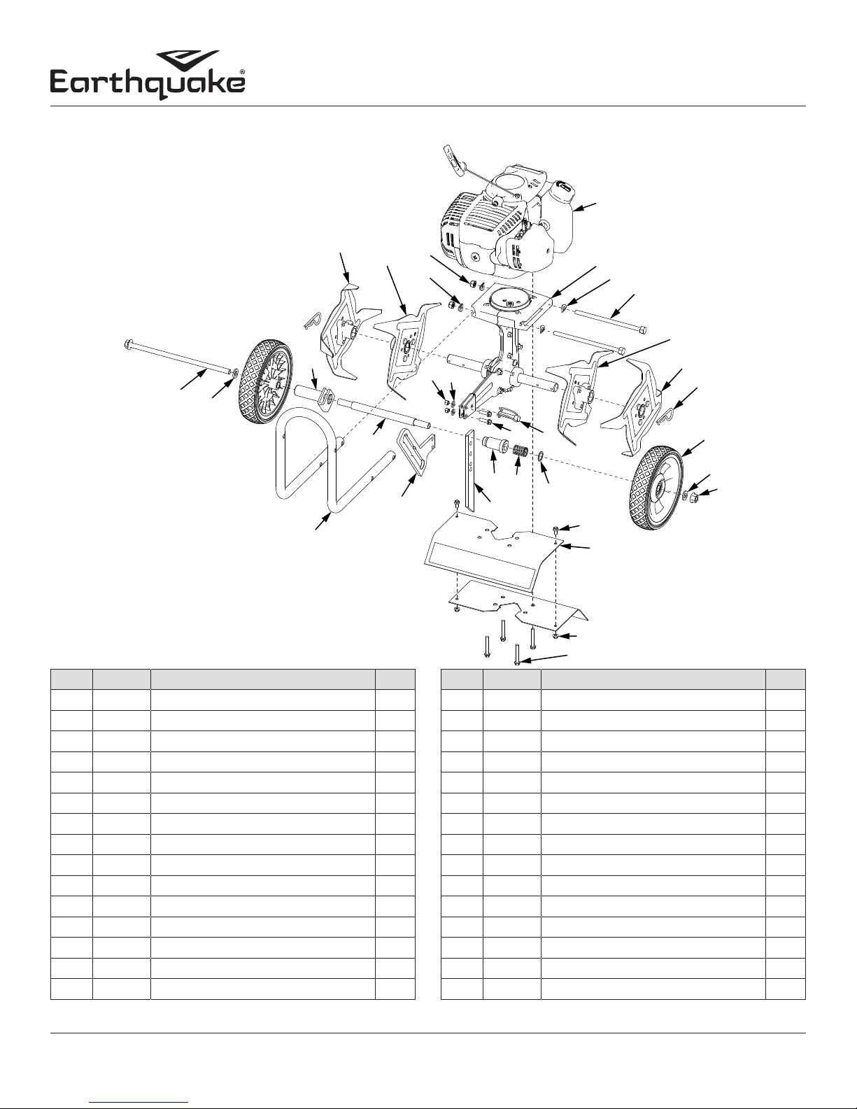
10
ILLUSTRATED PARTS BREAKDOWN Hood & Tines Parts Explosion & Parts List
1
Operator's Manual
MC440 4-Cycle Cultivator
26
28
29
30
3
3
2
4
5
27
2122
6
7
9
23
20
19
8
9
17
16
15
14
25
24
18
13
12
11
KEY PART # DESCRIPTION QT Y.
1 23491 ENGINE 40CC 4-CYCLE 1
2 26013 TRANSMISSION ASSEMBLY 1
3 4641 CURVED WASHER M8 4
4 46141 BOLT M8 X 1.25 X 160 MM 2
5 4602 TINE C ASSEMBLY 1
6 4604 TINE D ASSEMBLY 1
7 4652 HAIRPIN 5/8 X 3/4 IN 2
8 13189 WHEEL 180 X 38 MM GREY 2
9 2431 WASHER M10 X 20 X 2 MM 2
10 13048 LOCK NUT M10 X 1.5 FLANGE 1
11 4625 BOLT M6 X 1.0 X 42 MM FLANGE 4
12 400020 LOCK NUT M5 X 0.8 MM FLANGE 2
13 23441 TINE SHIELD WITH WARNING 2
14 176 BOLT M5 X 0.8 X 10 MM FLANGE 2
15 13230 WASHER 16 X 21 X 1 MM 1
KEY PART # DESCRIPTION QT Y.
16 4685 WHEEL LOCK SPRING 1
17 4684 WHEEL LOCK TUBE 1
18 4600 DRAG STAKE 1
19 18039 LOCK PIN 8 X 40 MM 1
20 46142 BOLT M6 X 1.0 X 20 MM FLANGE 2
W1200117
21 WASHER M6 X 12 X 1 MM 2
22 4650 NUT M6 X 1.0 NYLOCK 2
23 4674 WHEEL AXLE TUBE 1
24 4673 WHEEL HOLDER 1
25 12811 LOWER HANDLEBAR 1
26 4687 BOLT M10 X 1.5 X 225 MM FLANGE 1
27 4678 WHEEL GUIDE TUBE 1
28 4601 TINE A ASSEMBLY 1
29 4603 TINE B ASSEMBLY 1
30 400023 NUT M8 X 1.25 NYLOCK 2
Check for parts online at www.getearthquake.com or call 800-345-6007 M-F 8-5 17
Page 18
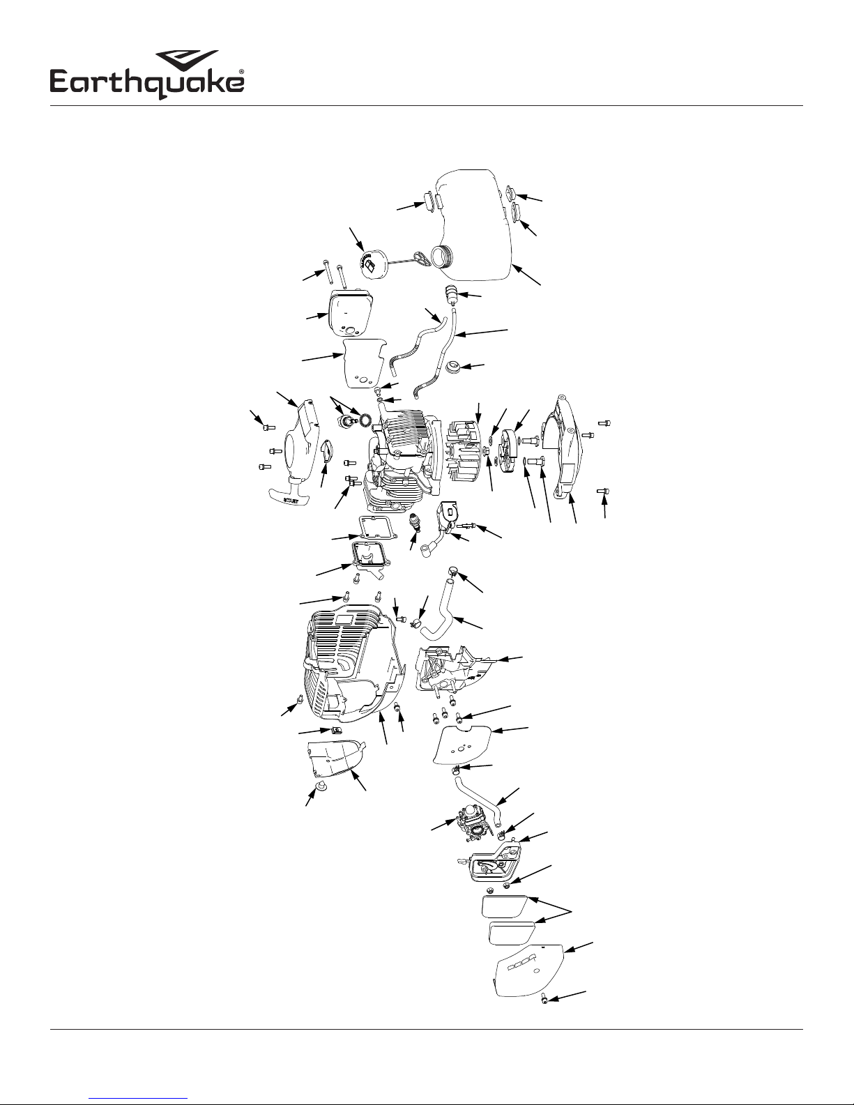
1,23
ILLUSTRATED PARTS BREAKDOWN Engine Parts Explosion
Operator's Manual
MC440 4-Cycle Cultivator
23
26,27
26
25,26
20
1,20
24
22
1
20,21
30,34
31,34
29
28
15,16
34,36
14
7,11
34,35,
37
12
36
34,36
38
12,13
7,11
7
34,36
39,40
32,34
33,34
34
40
40,41
40,42
1
43
18
15,16
16,19
10
1,10
8,9
16
15,16
16,17
16,18
Check for parts online at www.getearthquake.com or call 800-345-6007 M-F 8-5
8
6,7
7
6,7
5
4,5
3,5
2,5
1,5
Page 19

ILLUSTRATED PARTS BREAKDOWN Engine Parts List
Operator's Manual
MC440 4-Cycle Cultivator
KEY PART # DESCRIPTION QT Y.
1 26205 BOLT M5 X 0.8 X 16 MM W/WASHER 17
2 13197 AIR FILTER COVER 1
3 26996 KIT AIR FILTER ELEMENTS 1
4 400020 LOCK NUT M5 X 0.8 MM FLANGE 2
5 13363 AIR FILTER KIT 1
6 23271 HOSE CLAMP CRANKCASE 2
7 13394 BREATHER HOSES KIT 1
8 13329 CARBURETOR KIT 1
9 13299 CARBURETOR GASKET 1
10 13390 CARBURETOR INSULATOR KIT 1
11 13395 HOSE CLAMP VALVE COVER 2
12 13400 IGNITION COIL KIT 1
13 26866 BOLT M4 X 0.7 X 20 MM W/WASHER 2
14 13243 SPARK PLUG NGK CMR6A 1
15 26867 BOLT M5 X 0.8 X 12 MM W/WASHER 3
16 18497 ENGINE SHROUD KIT 1
17 11043 SHROUD CAP SPARK PLUG ACCESS 1
18 11044 SCREW 3/16 X 1/2 IN PHILLIPS 1
19 22631 CLIP NUT 3/16 IN 1
20 13298 VALVE COVER KIT 1
21 13324 GASKET VALVE COVER 1
22 13244 RECOIL CLUTCH 1
KEY PART # DESCRIPTION QT Y.
23 13342 RECOIL ASSEMBLY 1
24 13393 OIL CAP WITH ORING 1
25 13202 HEAT SHIELD MUFFLER 1
26 13391 MUFFLER KIT 1
27 13181 BOLT M5 X 0.8 X 50 MM SOCKET 2
28 13320 WASHER M6 X 10 X 1 MM 1
29 19919 BOLT M6 X 1.0 X 10 SOCKET 1
30 19236 GAS CAP SELF VENTING 1
31 13295 RUBBER GAS TANK HOLDER TOP 1
32 13296 RUBBER GAS TANK HOLDER LEFT 1
33 13297 RUBBER GAS TANK HOLDER RIGHT 1
34 13388 GAS TANK KIT 1
35 17992 FUEL FILTER ALUMINUM CORE 1
36 13308 FUEL LINES KIT 1
37 13241 FLYWHEEL 1
38 300337 LOCK NUT M8 X 1.25 FLANGE 1
39 300462 WASHER 8.4 X 15.8 X 1.6 MM 2
40 11235 CLUTCH KIT 1
41 300449 WAVE WASHER 10 X 15 X 0.25 MM 2
42 300450 BOLT M8 X 1.25 X 25MM SHOULDER 2
43 26868 MOUNT RING AND SHROUD 1
Check for parts online at www.getearthquake.com or call 800-345-6007 M-F 8-5 19
Page 20
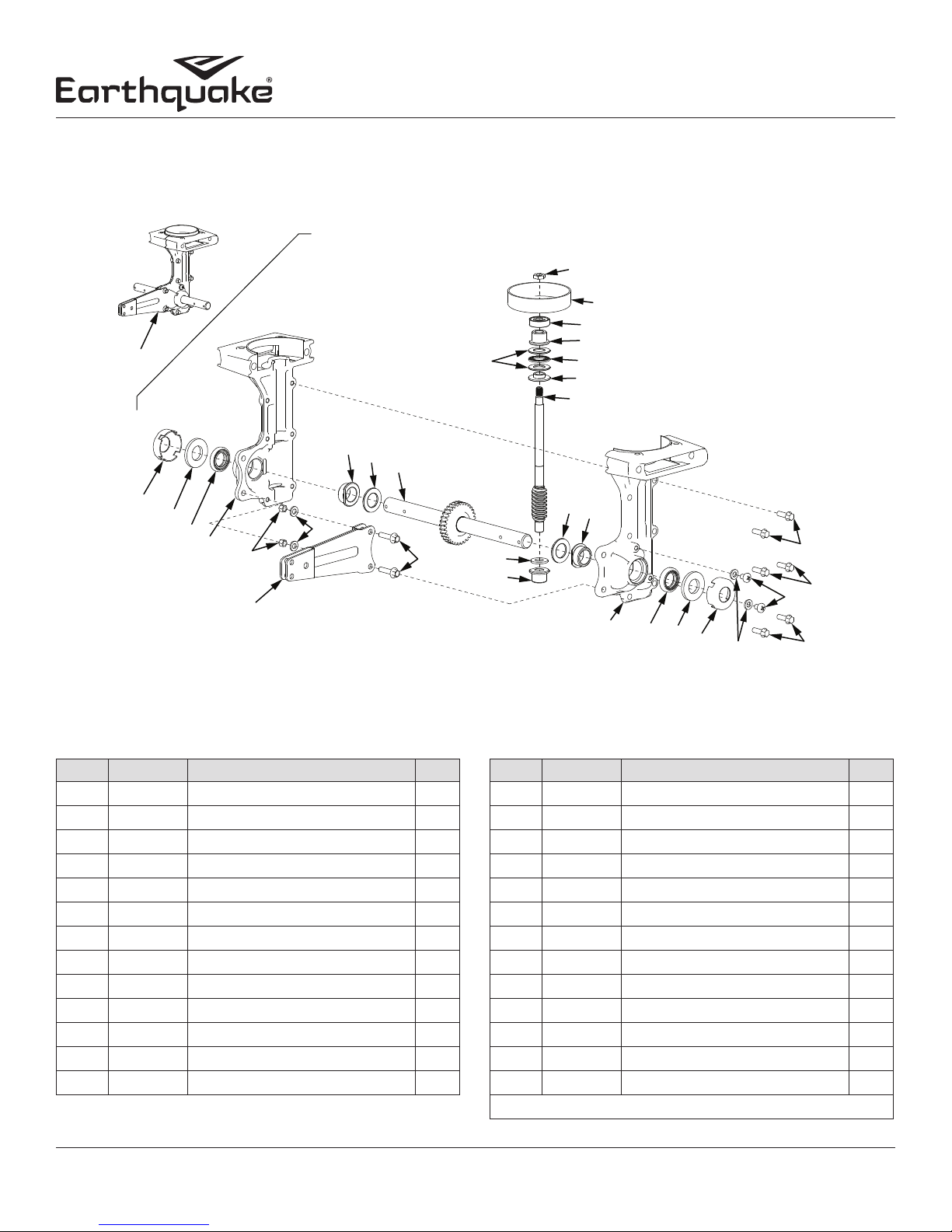
ILLUSTRATED PARTS BREAKDOWN Transmission Parts Explosion & Parts List
21
20
19
14
1
10
11
12
17, 26
18, 26
16
15
Operator's Manual
MC440 4-Cycle Cultivator
2
3
4
5
6
7
9
8
KEY PART # DESCRIPTION QT Y.
1 26013 TRANSMISSION ASSEMBLY 1
2 46144 DUST CAP 2
3 4606 FIBER WASHER 2
4 4646 TINE SHAFT SEAL 2
5* TRANSMISSION CASTING LEFT 1
6 4650 NUT M6 NYLOCK 2
7 W1200117 WASHER M6 X 12 X 1 MM 2
8 4633 WHEEL & DRAG STAKE MOUNT 1
9 13600 BOLT M6 X 1.0 X 25 HEX FLANGE 2
10 25159 TINE SHAFT BUSHING STEEL 2
11 4610 TINE SHAFT SHIM 2
12 4651 GEAR AND TINE SHAFT ASSY 1
13 4616 BUSHING SPACER 1
11
10
13
24
14
24
25
22
KEY PART # DESCRIPTION QT Y.
4
3
2
23
24
14 4614 DRIVE SHAFT BUSHING BRONZE 2
15 21953 DRIVE SHAFT 1
16 4617 THRUST BEARING REDUCER 1
17 4618 THRUST WASHER 2
18 4619 THRUST BEARING CAGE 1
19 4623 BALL BEARING 9 X 26 X 8 MM 1
20 300414 CLUTCH DRUM 1
21 4620 JAM NUT M8 1
22* TRANSMISSION CASTING RIGHT 1
23 26997 WASHER M6 X 12 X 1 MM CU 2
24 4647 BOLT M6 X 1.0 X 18 HEX FLANGE 6
25 13447 BOLT M6 X 1.0 X 8 PHILLIPS 2
26 4615 KIT THRUST BEARING SET 1
* PURCHASE TRANSMISSION ASSEMBLY 26013
20
Check for parts online at www.getearthquake.com or call 800-345-6007 M-F 8-5
Page 21
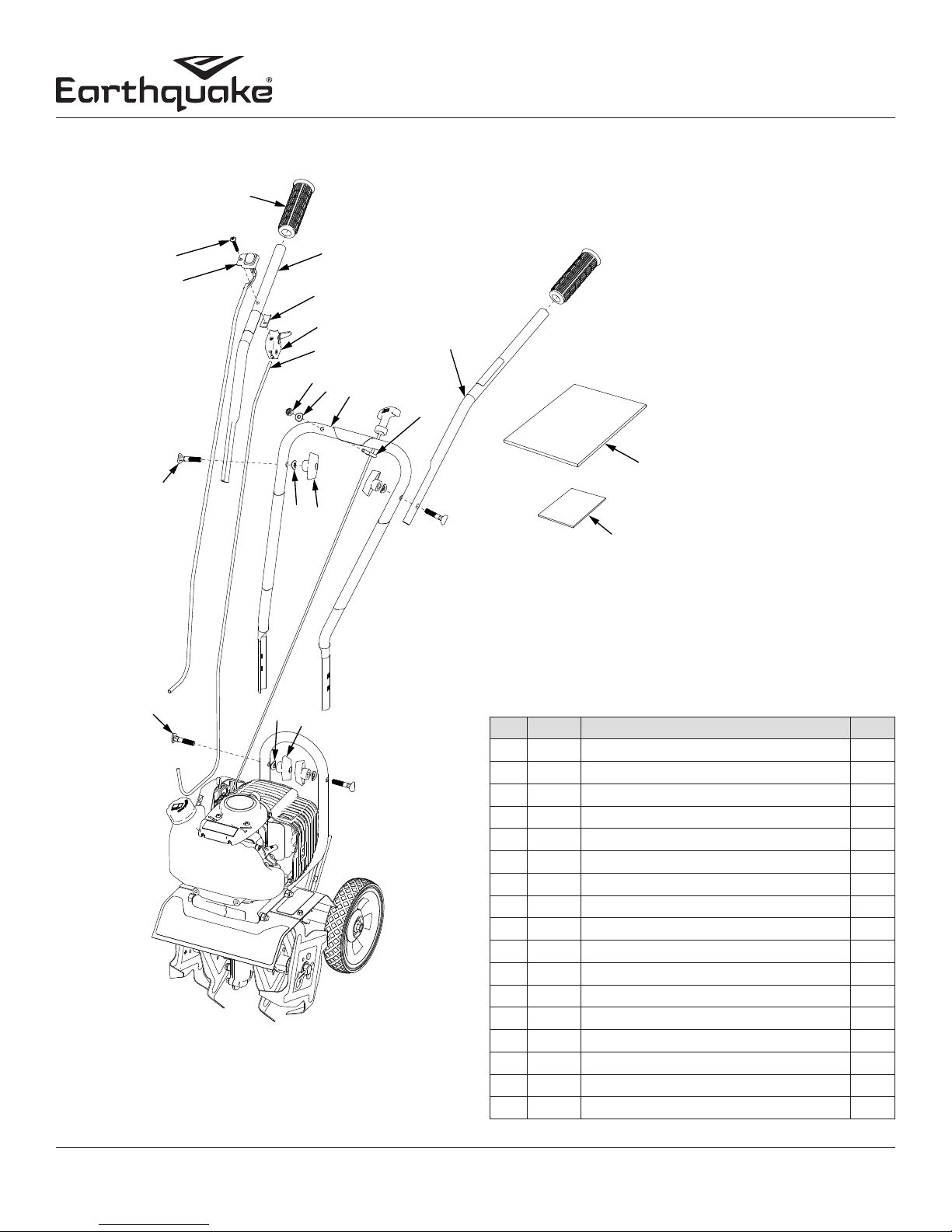
ILLUSTRATED PARTS BREAKDOWN Handlebar Parts Explosion & Parts List
13
1
Operator's Manual
MC440 4-Cycle Cultivator
13
2
3
4
5
6
7
8
9
10
12
11
16
14
15
17
14
15
KEY PART # DESCRIPTION Q TY.
1 13309 HANDLE GRIP TEXTURED 2
2 4618 BOLT 1024 X 11/4 IN PHILLIPS 1
3 21284 SWITCH ON/OFF WIRE ASSEMBLY 1
4 23444 HANDLEBAR UPPER RIGHT W/WARNING 1
5 12633 HANDLEBAR RUBBER PAD 15 X 28.5 MM 1
6 4809 TRIGGER ASSEMBLY SHORT THROW 1
7 14645 THROTTLE CABLE 1
8 64131 LOCK NUT M6 X 1.0 FLANGE 1
9 10800 CURVED WASHER M6 1
10 13190 HANDLEBAR MIDDLE 1
11 400025 EYEBOLT M6 X 1.0 X 12 MM 1
12 23445 HANDLEBAR UPPER LEFT W/WARNING 1
13 4642 SADDLE BOLT M8 X 1.25 4
14 4641 CURVED WASHER M8 4
15 4640 THANDLE NUT M8 X 1.25 4
16 23438 MANUAL PARTS BAG 1
17 12621 HARDWARE PARTS BAG 1
Check for parts online at www.getearthquake.com or call 800-345-6007 M-F 8-5 21
Page 22

MC440 4-Cycle Cultivator
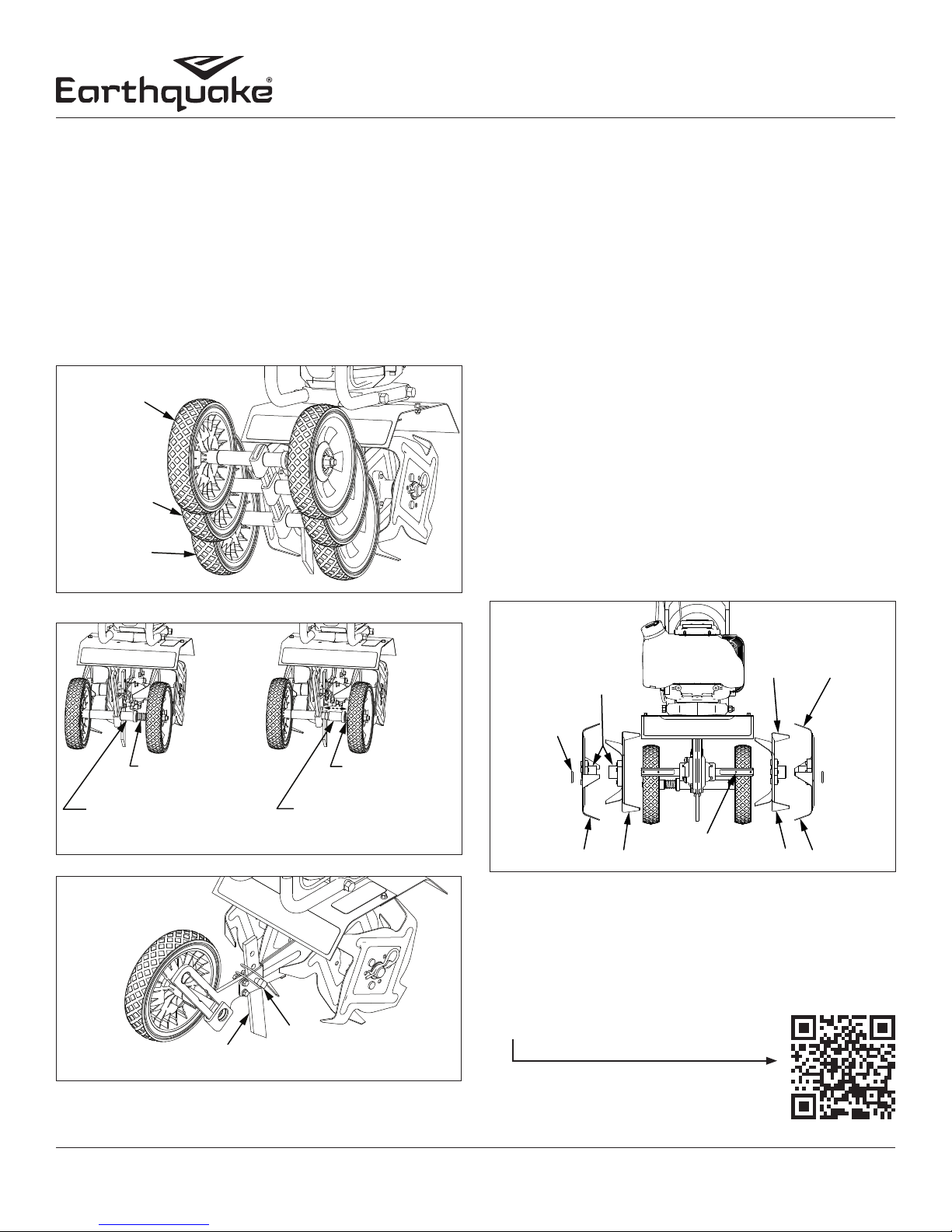
15073 BORDEREDGER KIT INSTALLATION OPTIONAL ACCESSORY
The Border-Edger Kit is a useful tool for making clean cuts in
the lawn along the borders of gardens, ower beds, walkways,
and driveways for a well manicured look. To install the BorderEdger Kit, do the following:
INSTALLATION
1. Make sure the cultivator is not running by turning the ON/
OFF switch to the OFF position.
2. Remove the hairpins from both sides of the tine shaft.
3. Remove the cultivating tines from the shaft.
4. Remove the drag stake and lock pin from the unit.
5. Store the tines and save the (2) hairpins; they will be used on
the Border-Edger Kit.
6. Slide the border-edger tine onto either side of the tine
shaft. Make sure that the hub collar of the border-edger tine
faces outward, away from the transmission of the cultivator.
SEE FIGURE 13
7. Take the (2) hairpins saved in Step 4 and insert them through
the inner and outer holes in the tine shaft on each side of the
border-edger tine to secure the tine blade in place on the
shaft. SEE FIGURE 13
8. Slide the border-edger wheel onto the opposite side of the
tine shaft as far as it will go.
9. Insert the remaining (1) hairpin, that came with the kit,
through the inner hole to secure the wheel. SEE FIGURE 13
10. Set the cultivator wheels to the HIGHEST (top) position.
SEE FIGURE 5 (PAGE 12)
BORDER-EDGER
WHEEL
TINE SHAFT
HAIR PIN
FIGURE 13
Operator's Manual
DRAG STAKE
REMOVED
BORDER-EDGER
TINE
HUB COLLAR
PARTS BREAKDOWN
ITEM
PART
NO.
1 15009 BORDEREDGER TINE 1
2 46131 BORDER-EDGER WHEEL 1
3 46134 HAIRPIN 1
DESCRIPTION QT Y.
NO.
CAUTION
BE AWARE THAT THE CULTIVATOR COULD
UNEXPECTEDLY BOUNCE UPWARD, OR JUMP
FORWARD IF THE TINE STRIKES CONCRETE,
PAVEMENT, OR OTHER HARD SURFACES OR HARD
OBSTACLES BURIED UNDER GROUND.
22
Check for parts online at www.getearthquake.com or call 800-345-6007 M-F 8-5
Page 23
Operator's Manual
MC440 4-Cycle Cultivator
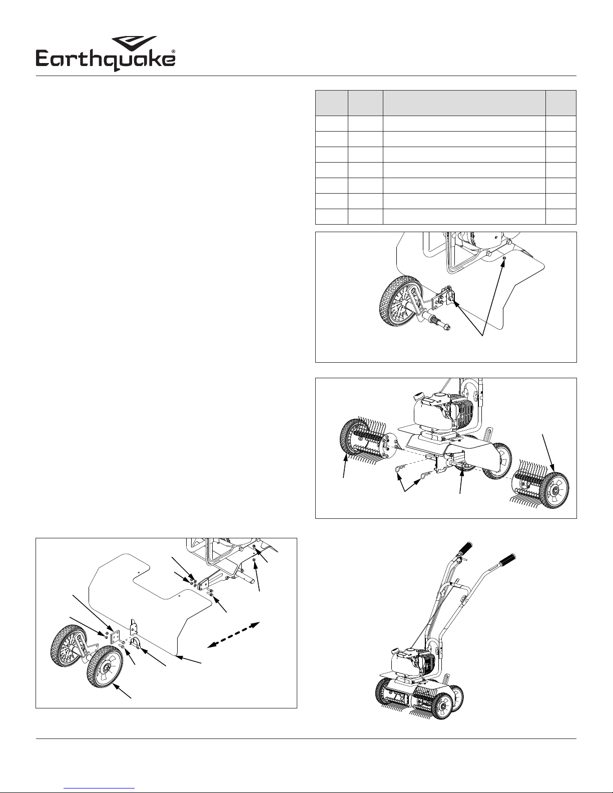
DK43 DETHATCHER KIT INSTALLATION
OPTIONAL ACCESSORY
The Dethatcher Kit is very effective for lifting away the excessive
matted layers of thatch that can prevent moisture, oxygen and
nutrients from penetrating the soil and can harbor disease and
insects. Use in Spring, Summer, and Fall to bring life and color
back to your lawn.
1. Turn the ON/OFF switch to the OFF position. Remove the
cultivating tines or other working tools and the drag stake.
2. Unscrew mount bolts/nuts that connect the wheel bracket to
the drag stake mount and set wheel bracket aside.
SEE FIGURE14
3. Slide dethatcher shield over the unit’s tine shield from the rear of
the unit and secure using bolts and nuts. SEE FIGURES 14 & 15
4. Secure the lower part of the dethatcher shield to the drag stake
mount using the lock pin. SEE FIGURE 14 & 15
5. Install wheel extension plate (4676) using additional bolts
(46142) and nuts (4650). Make sure wheel extension is facing
the correct direction. (The side, with the two holes flush to the
edge, connects to the drag stake mount) SEE FIGURE 14
a. Attach the wheel extension to the drag stake mount
with mount bolts and nuts from unit.
b. Attach the wheel bracket to the wheel extension with
bolts and nuts included with the Dethatcher Kit.
6. Slide the Left and Right Dethatcher Assemblies onto the tine
shaft making sure the Right Assembly is installed on the right
side and Left Assembly is installed on the left side as defined
from the user’s position. SEE FIGURE 16
7. Secure dethatcher assemblies using the two hairpins (46134)
from the Dethatcher Kit through the inner holes of the tine
shaft. SEE FIGURE 16
NOTE: The drag stake must NOT be used when using the
dethatcher kit.
ITEM
NO.
PART
1 46134 HAIR PIN 2
2 4647 BOLT M6 X 1.0 X18 HEX FLANGE 2
3 4650 NUT M6 NYLOCK 2
4 4676 EXTENSION PLATE DETHATCHER 1
5 4707 DETHATCHER ASSEMBLY LEFT 1
6 4708 DETHATCHER ASSEMBLY RIGHT 1
7 4710 DETHATCHER SHIELD 1
DESCRIPTION QT Y.
NO.
SHIELD SECURED WITH LOCK
PIN AND TINE SHIELD BOLTS
FIGURE 15
DETHATCHER
ASSEMBLY
RIGHT
DETHATCHER
ASEMBLY
HAIR PINS
TINE
SHAFT
FIGURE 16
LEFT
WASHER
EXTENSION
PLATE
NUT
(4650)
NUT
BOLT
(4647)
WHEEL BRACKET ASSEMBLY
LOCK
PIN
DETHATCHER
FIGURE 14
Check for parts online at www.getearthquake.com or call 800-345-6007 M-F 8-5 23
BOLT
NUT
BOLT
SHIELD
Page 24

Operator's Manual
MC440 4-Cycle Cultivator
WARRANTY TERMS AND CONDITIONS
Ardisam, Inc. (Ardisam) warrants this cultivator under a five-year limited warranty to be free from defects in the
material or workmanship or both for a period not exceeding sixty consecutive months from the date of original
purchase by the first retail consumer or first commercial end user. This warranty does not apply to the engine
mounted on the product. Refer to EPA warranty for engine warranty details. “Consumer use,” means personal
recreational use by a retail consumer. “Commercial use,” or “commercial application“ means all other uses,
including use for commercial, income producing or rental purposes. Once a product has experienced commercial
use, it shall thereafter be considered as a commercial use product for the purpose of this warranty. This warranty
applies to the original owner that provides a proof of purchase. This warranty is not transferable. The warranty
period begins on the date of purchase by the first retail consumer or commercial end user, and continues for the
sixty month consecutive period thereafter. Any unit used in a commercial application is covered for a period of 90
days after purchase by the first commercial end user. For the warranty to be valid, the product must be registered
online within 30 days of purchase, or the warranty card must be filled out and received by Ardisam within 30 days
of purchase. Ardisam shall not be obligated for transportation charges that result from repair or replacement
under the terms of this warranty. Transportation charges are the sole responsibility of the purchaser.
This warranty excludes tines due to normal wear, wear items such as wheels, grips and cables, routine
maintenance items such as filter elements, o-rings, seals, lubricants, and tune-ups, rotating parts, accessory parts
such as hiller furrowers, edger kits, and dethatcher kits, running the cultivator on straight gasoline or with a
fuel:oil ratio other than 50:1. Negligent use such as using the cultivator for a purpose other than for which it was
designed and manufactured, continued use of cultivator after sudden change in vibration, using the cultivator
in violation of local codes, ordinances and good trade practices voids this warranty. *These warranties apply only
to products which have not been subjected to negligent use, abuse, misuse, overload, improper installation,
alteration, accident, acts of God (or other events beyond Ardisam’s control) lightning, vandalism, unauthorized
parts, or if repairs have been performed at a non-authorized service facility. These warranties shall not cover
damage from normal wear and tear, normal maintenance parts and services, or improper installation, operation,
storage, or maintenance; nor operating the equipment above recommended maximums as stated in this manual
and the accompanying engine manual.
This limited warranty applies to defects in the material or workmanship of the product only. There is no other
express warranty. Implied warranties, including those of merchantability and fitness for a particular purpose,
are limited to one year from purchase, or to the extent permitted by law. All other implied warranties are
excluded. Liability for incidental or consequential damages are excluded to the extent exclusion is permitted by
law. Ardisam does not assume, and does not authorize any other person to assume for Ardisam, any liability in
connection with the sale of Ardisam products. To be at “No Charge,” warranty work must be sent directly to
and performed by Ardisam or an Ardisam Authorized Warranty Service Facility. To obtain warranty service
and/or replacement instructions, contact the Ardisam Customer Service Department at 800-345-6007. If you
choose to ship your product to Ardisam for warranty repair, you must first have prior approval from Ardisam
by calling the Ardisam Customer Service Department for a return material authorization number (RMA#).
Under these circumstances, all items must be shipped prepaid. Ardisam will, in its discretion, at no charge,
repair or replace any defective part to which this warranty applies. Ardisam retains the right to change models,
specifications and price without notice. Ardisam shall not be obligated to ship any repair or replacement product
to any location outside of the United States of America or Canada. Some states and countries do not allow the
limitations on how long an implied warranty lasts, or the exclusion or limitation of incidental or consequential
damages, so the above limitation may not apply to you. This warranty gives you specific legal rights, and you may
also have other rights which vary from state to state and country to country.
24
Check for parts online at www.getearthquake.com or call 800-345-6007 M-F 8-5
Page 25

NOTES
Operator's Manual
MC440 4-Cycle Cultivator
Check for parts online at www.getearthquake.com or call 800-345-6007 M-F 8-5 25
Page 26

Manuel de l’utilisateur
EMPLACEMENT
RO DE
Motobineuse 4 temps MC440
INTRODUCTION
Nous vous félicitons pour votre investissement dans la qualité. Merci d’avoir acheté une motobineuse 4 temps Earthquake®. Nous
avons veillé à ce que ce cultivateur respecte les normes les plus élevées en matière d’utilisabilité et de durabilité. Moyennant des
soins corrects, elle offrira de nombreuses années de service fiable.
Veuillez lire ce manuel en entier avant de l’installer et de l’utiliser. Earthquake se réserve le droit de changer, modifier ou
améliorer ce produit et cette documentation à tout moment sans préavis.
SOMMAIRE
Enregistrement ..................................................................................................................................................................................................................................1
Avertissements et mesures de précaution ..........................................................................................................................................................................2-6
Caractéristiques/Données techniques ..................................................................................................................................................................................... 7
Déballage et assemblage .............................................................................................................................................................................................................. 8
Fonctionnement .........................................................................................................................................................................................................................8-11
Entretien et entreposage ...................................................................................................................................................................................................... 12-14
Dépannage et réparation ..................................................................................................................................................................................................... 14-15
Pièces détachées .....................................................................................................................................................................................................................16-20
Installation du kit coupe-bordure 15073 ...............................................................................................................................................................................21
Installation du kit scarificateur DK43 ......................................................................................................................................................................................22
Garantie .............................................................................................................................................................................................................................................23
INFORMATIONS FÉDÉRALES RELATIVES AUX ÉMISSIONS
Earthquake garantit à l’acheteur de détail d’origine que ce petit moteur non routier a été conçu, fabriqué et équipé de manière à
se conformer, au moment de la vente initiale, aux règlements en vigueur de l’U.S. Environmental Protection Agency (EPA).
ENREGISTREMENT ET SERVICE APRÈSVENTE
Consigner le numéro de modèle et le numéro de série du moteur dans l’espace prévu pour
y accéder facilement lors des commandes de pièces détachées ou demandes d’assistance
technique. À l’exception des articles couverts par la garantie sur le contrôle des émissions, la
garantie est valable uniquement si l’enregistrement dûment rempli est reçu par Ardisam dans
les 30 jours après l’achat. (POUR PLUS DE RENSEIGNEMENTS, VOIR LA SECTION SUR LA
GARANTIE.) L’enregistrement de la garantie peut se faire en ligne à www.getearthquake.com
ou par courrier à: Ardisam, 1160 Eighth Avenue, Cumberland, WI 54829, États-Unis. En l’absence
d’ordinateur, appeler notre service après-vente au (800) 345-6007 du lundi au vendredi de 8h00
à 17h00 HNC.
RENSEIGNEMENTS SUR LE PROPRIÉTAIRE
Nom du propriétaire:
Adresse du propriétaire:
Ville : État/Province: Code postal :
Numéro de modèle: Numéro de série:
Date d’achat:
Notes:
DU NUMÉ
SÉRIE
Le présent manuel peut contenir des informations concernant plusieurs modèles. Lire ce manuel et le conserver pour toute consultation
ultérieure. Ce manuel contient des renseignements importants sur la SÉCURITÉ, l’ASSEMBLAGE, l’UTILISATION et l’ENTRETIEN. Le
propriétaire doit veiller à ce que toute la documentation pertinente accompagne le produit. Cette documentation comprend le MANUEL,
la NOMENCLATURE DES PIÈCES et les GARANTIES. Cette documentation doit être incluse pour assurer le respect des réglementations en
vigueur. Ce manuel doit rester avec le produit même s’il est revendu.v
1
Voir les pièces détachées en ligne à www.getearthquake.com ou composer le 800-345-6007 L-V 8-17
Page 27

Manuel de l’utilisateur
Motobineuse 4 temps MC440
AVERTISSEMENTS ET MESURES DE
PRÉCAUTION
RESPONSABILITÉ DU PROPRIÉTAIRE
L’assemblage correct et l’utilisation sûre et efficace de la
machine relèvent de la responsabilité du propriétaire.
• Lire et suivre toutes les instructions de sécurité.
• Suivre avec attention toutes les instructions d’assemblage.
• Entretenir la machine conformément aux instructions
et au calendrier figurant dans le manuel de l’utilisateur
Earthquake.
• S’assurer que quiconque utilise la machine est familiarisé
avec toutes les commandes et mesures de précaution.
MESSAGES SPÉCIAUX
Ce manuel contient des messages spéciaux attirant l’attention
sur des problèmes de sécurité et dommages potentiels à la
machine, ainsi que des informations utiles sur le fonctionnement
et l’entretien. Veiller à lire toutes ces informations avec attention
pour éviter les blessures et les dommages à la machine.
REMARQUE : Des informations générales sont fournies à
travers ce manuel pouvant aider l’opérateur dans l’utilisation
ou l’entretien de la machine.
Ce symbole signale des instructions de sécurité
importantes qui doivent être respectées pour ne
pas mettre en danger la sécurité des personnes.
Lire et respecter toutes les instructions du manuel
avant de tenter de faire fonctionner cet appareil.
AVIS
AVIS INDIQUE QUE VOTRE ÉQUIPEMENT PEUT ÊTRE
ENDOMMAGÉ SI LES INSTRUCTIONS DE SÉCURITÉ QUI
SUIVENT CE MOT DU SIGNAL NE SONT PAS OBLIGEES.
ATTENTION
ATTENTION INDIQUE UN RISQUE QUI, SI NON ÉVITÉ, PEUT
ENTRAÎNER DES BLESSURES ET / OU DES DOMMAGES
MATÉRIELS.
AVERTISSEMENT
AVERTISSEMENT INDIQUE UN RISQUE QUI, SI NON ÉVITÉ,
PEUT ENTRAÎNER LA MORT OU DES BLESSURES GRAVES ET
/ OU DES DOMMAGES MATÉRIELS.
DANGER
UN DANGER INDIQUE UN RISQUE QUI, SI NON ÉVITÉ, PEUT
ENTRAÎNER DES BLESSURES GRAVES OU DES BLESSURES
GRAVES ET / OU DES DOMMAGES MATÉRIELS.
IMPORTANT
IMPORTANT INDIQUE LES RENSEIGNEMENTS UTILES POUR
L’ASSEMBLAGE, L’UTILISATION OU L’ENTRETIEN DE VOTRE
APPAREIL.
AVANT DE FAIRE FONCTIONNER LE MOTEUR :
Veiller à lire cette section avec attention. Lire l’ensemble des
instructions d’utilisation et d’entretien de ce produit. Pour écarter
les risques de blessure grave ou de mort, veiller à respecter
toutes les instructions. Utiliser la machine conformément aux
instructions de sécurité fournies ici et tout au long du manuel.
Quiconque utilise cette machine doit lire les instructions et être
familiarisé avec les commandes.
Emploi prévu / emploi détourné
prévisible
IMPORTANT : Ceci est une motobineuse rotative motorisée qui
travaille le sol au moyen de fraises en rotation. Elle se conduit
à pied mais n’est pas autotractée et comporte un moteur à
combustion interne à essence qui entraîne les fraises. Elle ne
doit être utilisée à aucune autre fin.
DANGER
AVERTISSEMENT
AVERTISSEMENT PROPOSITION 65 DE CALIFORNIE
L’ÉCHAPPEMENT DU MOTEUR DE CE PRODUIT
CONTIENT DES SUBSTANCES CHIMIQUES DÉCLARÉES
RESPONSABLES DE CANCER, MALFORMATIONS
CONGÉNITALES OU AUTRES ANOMALIES DE LA
REPRODUCTION PAR L’ÉTAT DE CALIFORNIE.
AVERTISSEMENT
VEILLER À LIRE, À COMPRENDRE ET À RESPECTER
TOUTES LES INSTRUCTIONS DE SÉCURITÉ ET
D’UTILISATION FIGURANT DANS CE MANUEL AVANT
DE TENTER D’INSTALLER ET DE FAIRE FONCTIONNER
LA MACHINE.
TOUT MANQUEMENT À OBSERVER LES INSTRUCTIONS
DE SÉCURITÉ ET D’UTILISATION PEUT PROVOQUER
DES BLESSURES CORPORELLES GRAVES POUR
L’UTILISATEUR ET D’AUTRES PERSONNES PRÉSENTES
ET DES DÉGÂTS MATÉRIELS. LE TRIANGLE DANS
LE TEXTE SIGNIFIE QUE DES MISES EN GARDES ET
AVERTISSEMENT IMPORTANTS DOIVENT ÊTRE SUIVIS.
Voir les pièces détachées en ligne à www.getearthquake.com ou composer le 800-345-6007 L-V 8-17 2
Page 28

Manuel de l’utilisateur
Motobineuse 4 temps MC440
CONSIGNES GÉNÉRALES DE SÉCURITÉ
Lire, comprendre et respecter toutes les instructions figurant
sur la machine et dans le(s) manuel(s). Veiller à bien se
familiariser avec les commandes et la bonne utilisation de la
machine avant de la démarrer.
• Utiliser ce matériel exclusivement aux fins prévues.
• Veiller à se familiariser avec tous les autocollants de sécurité
et d’exploitation apposés sur ce matériel et sur tous ses outils
ou accessoires.
• Ne pas placer les mains ni les pieds sous ou à proximité d’une
pièce en rotation.
• Permettre l’utilisation de la machine uniquement à des
personnes responsables familiarisées avec les instructions.
Ne pas laisser d’enfant utiliser cette machine. Ne pas laisser
d’adulte utiliser cette machine sans instruction appropriée.
• Examiner avec soin la zone où la machine doit être utilisée
et éliminer tous les objets étrangers. Ce matériel peut
projeter violemment de petits objets et provoquer des
dégâts matériels ou des blessures graves. Rester à l’écart des
objets fragiles tes que les fenêtres de maison, automobiles,
serres, etc.
• Porter une tenue adaptée, notamment un blouson ou une
chemise à manches longues. Porter également un pantalon
long. Ne pas porter de pantalon court. Ne jamais porter de
sandales, chaussures de sport ni chaussures ouvertes et ne
jamais utiliser la machine pieds nus.
• Ne pas porter de vêtements flottants ni de bijoux. Ils peuvent
être happés par les pièces en mouvement. Toujours tenir les
mains, les pieds, les cheveux et les vêtements amples à l’écart
de toute pièce en mouvement du moteur et de la machine.
• Toujours porter des lunettes à coques ou des lunettes de
sécurité à écrans latéraux durant la marche de la machine
pour protéger les yeux des objets étrangers susceptibles
d’être projetés par la machine. Toujours porter une
protection auditive.
• Toujours porter des gants de travail et des chaussures
robustes. Porter des chaussures offrant une bonne
adhérence sur les surfaces glissantes. Les chaussures de
chantier ou bottines en cuir conviennent généralement
bien. Elles protègent les chevilles et les tibias de l’opérateur
contre les petits bouts de bois, échardes et autres débris.
• Il est conseillé de porter une protection de la tête contre
les projections de terre et petits cailloux et pour éviter
de heurter les branches basses et autres objets auxquels
l’opérateur n’aurait pas prêté attention.
• Ne pas utiliser la machine si tous les carters de protection et
autres dispositifs de sécurité ne sont pas en place.
• Voir les instructions du fabricant concernant l’utilisation et
la pose d’accessoires. Utiliser exclusivement des accessoires
homologués par le fabricant.
• Travailler uniquement durant la journée ou sous une bonne
lumière artificielle.
• Ne pas utiliser ce produit alors qu’on est fatigué ou sous
l’emprise de l’alcool, de drogues ou de médicaments
susceptibles de provoquer une somnolence ou d’altérer la
capacité à utiliser la machine en toute sécurité.
• Ne jamais utiliser la machine dans de l’herbe mouillée. Veiller
à toujours avoir le pied ferme; tenir fermement la poignée
et marcher avec la machine; ne jamais courir.
• Prendre garde à la circulation lors de l’utilisation de la
motobineuse à proximité d’une chaussée ou en traversant
une rue.
• Si le matériel commence à vibrer de façon anormale,
arrêter le moteur, mettre l’interrupteur Marche/Arrêt en
position Arrêt. Rechercher immédiatement la cause. Les
vibrations signalent généralement un problème. Si le
bruit ou les vibrations de la machine augmentent, arrêter
immédiatement et contrôler la machine.
• Ne jamais laisser la machine sans surveillance avec le moteur
en marche. Mettre l’interrupteur Marche/Arrêt en position
Arrêt.
• Contrôler régulièrement la machine. Vérifier qu’aucune pièce
n’est déformée, endommagée ni desserrée.
• La température du silencieux et des surfaces voisines peut
dépasser 65°C (150°F). Laisser le silencieux et les surfaces
du moteur refroidir avant de les toucher. Ne jamais soulever
ni porter la machine avec le moteur en marche.
• L’exposition prolongée au bruit et aux vibrations produites
par du matériel à moteur à essence doit être évitée. Faire des
pauses intermittentes et/ou porter un protection auditive
contre le bruit du moteur, ainsi que des gants de travail épais
pour réduire les vibrations dans les mains.
• Maintenir tous les boulons, vis et écrous bien serrés.
• Ne pas transporter la machine d’un endroit à l’autre avec le
moteur en marche.
• Si la machine est emballée, toujours la déplacer avec l’aide
d’une autre personne.
• Consulter la réglementation en vigueur concernant les
restrictions d’âge pour l’utilisation de cette machine.
CONSIGNES DE SÉCURITÉ PROPRES AU PRODUIT
• Ne pas biner au-dessus de canalisations souterraines,
notamment conduites d’eaux, conduites de gaz, câbles
électriques ou autres tuyaux. Ne pas utiliser la machine dans
un sol contenant de grosses roches et autres objets étrangers
susceptibles d’endommager le matériel.
• Après avoir heurté un objet étranger, couper le moteur.
Mettre l’interrupteur Marche/Arrêt en position Arrêt.
Contrôler l’état de la machine. En cas de dommages, réparer
avant de démarrer et d’utiliser la machine.
• Les fraises de la motobineuse ne doivent pas tourner lorsque
le moteur est au ralenti. Si elles tournent avec le moteur au
ralenti, obtenir des instructions auprès du service aprèsvente Earthquake.
• Si un objet s’est logé dans les fraises, mettre l’interrupteur
Marche/Arrêt en position Arrêt et laisser refroidir avant de
tenter de déloger l’objet étranger.
• L’embrayage transfère un maximum de couple au bout
de deux heures de marche normale. Durant cette phase
de rodage, il est possible que l’embrayage patine. Pour
fonctionner correctement, l’embrayage doit être gardé à
l’abri d’huile ou autre forme d’humidité.
3
Voir les pièces détachées en ligne à www.getearthquake.com ou composer le 800-345-6007 L-V 8-17
Page 29

Manuel de l’utilisateur
Motobineuse 4 temps MC440
DANGER
LES MOTEURS DÉGAGENT DU MONOXYDE DE
CARBONE, UN GAZ TOXIQUE INODORE ET INCOLORE.
DU MONOXYDE DE CARBONE PEUT ÊTRE PRÉSENT
MÊME SI ON NE PEUT NI SENTIR NI VOIR DE GAZ
D’ÉCHAPPEMENT DU MOTEUR. L’INHALATION
DE MONOXYDE DE CARBONE PEUT PROVOQUER
LA NAUSÉE, LA PERTE DE CONSCIENCE, VOIRE
LA MORT, EN PLUS D’UN ÉTAT DE SOMNOLENCE,
D’ÉTOURDISSEMENT ET DE CONFUSION.
EN PRÉSENCE DE L’UN QUELCONQUE DE CES
SYMPTÔMES, SORTIR À L’AIR FRAIS ET OBTENIR
IMMÉDIATEMENT DES SOINS MÉDICAUX.
MESURES DE PRÉCAUTIONS CONCERNANT LE
MOTEUR
Si le produit est fourni avec manuel séparé pour le moteur,
veiller à bien le lire et à suivre toutes les mises en garde et
mesures de précaution qu’il contient, en plus de celles de
ce manuel.
Empêcher l’intoxication au monoxyde de carbone
• Toujours démarrer et faire tourner le moteur à l’extérieur. Ne
pas démarrer ni faire tourner le moteur dans un espace fermé,
même avec des portes ou des fenêtres ouvertes.
• Ne jamais essayer de ventiler l’échappement du moteur
à l’intérieur. Le monoxyde de carbone peut atteindre des
niveaux dangereux très rapidement.
• Ne jamais faire fonctionner le moteur à l’extérieur à un
endroit où les fumées d’échappement peuvent être aspirées
dans un bâtiment.
• Ne jamais faire fonctionner le moteur à l’extérieur dans un
endroit mal aéré où les fumées d’échappement peuvent être
piégées et difficiles à dissiper (exemples: fond de fouille ou
aires de travail entourées de collines).
• Ne jamais faire tourner le moteur dans un endroit fermé ou
partiellement fermé (exemples: bâtiments fermés sur un ou
plusieurs côtés, tente, abri à voiture ou sous-sol).
• Toujours faire fonctionner le moteur avec l’échappement et
le silencieux pointés dans la direction opposée à l’opérateur.
• Ne jamais pointer le silencieux d’échappement vers
quiconque. Les personnes présentes doivent toujours se
tenir à bonne distance de la machine et de ses outils en
marche.
• Ne pas modifier les réglages du régulateur de moteur et ni
faire tourner le moteur en surrégime.
Feux d’essence et manipulation du carburant
Faire preuve de beaucoup de prudence pour manipuler l’essence
et autres carburants. Ils sont inflammables et leurs vapeurs sont
explosives.
• Veiller à bien entreposer le carburant de réserve dans un
bidon approprié et à l’écart de tout risque d’incendie.
• Empêcher les incendies et explosions causés par une
ATTENTION
LES GAZ CHAUDS SONT UN SOUSPRODUIT NORMAL
DE LA MARCHE D’UN MOTEUR À COMBUSTION
INTERNE. SUIVRE TOUTES LES INSTRUCTIONS DE
SÉCURITÉ POUR ÉVITER LES BRÛLURES ET LES
INCENDIES.
AVERTISSEMENT
NE JAMAIS ALTÉRER NI MODIFIER LE MOTEUR TEL
QU’IL EST LIVRÉ DE L’USINE. LA MODIFICATION OU
L’ALTÉRATION DU MOTEUR PEUT ENTRAÎNER DES
BLESSURES GRAVES OU LA MORT.
AVANT DE TRAVAILLER SUR LE MOTEUR OU LA
MACHINE OU DE CHANGER DES PIÈCES, VEILLER
À TOUJOURS METTRE L’INTERRUPTEUR MARCHE/
ARRÊT EN POSITION ARRÊT.
décharge d’électricité statique. Utiliser exclusivement des
bidons à carburant portables non métalliques homologués
par Underwriter’s Laboratory (U.L.) ou par l’American Society
for Testing & Materials (ASTM).
• Toujours faire le plein du réservoir d’essence à l’extérieur,
dans un endroit bien aéré. Ne jamais remplir le réservoir
à l’intérieur (exemples: sous-sol, garage, grange, remise,
maison, véranda, etc.). Ne jamais remplir le réservoir
près d’appareils à veilleuse, réchauffeurs et autres sources
d’inflammation. Si le réservoir doit être vidangé, le faire à
l’extérieur. Le carburant vidangé doit être conservé dans un
bidon spécifiquement conçu pour le carburant ou il doit être
éliminé avec précaution.
• Ne jamais ouvrir le bouchon du réservoir ni ajouter du
carburant avec le moteur en marche. Couper le moteur et
le laisser refroidir avant de refaire le plein.
• Ne jamais vidanger le carburant du moteur dans un endroit
fermé.
• Toujours essuyer l’excédent (débordement) de carburant
de la surface du moteur avant de démarrer. Nettoyer
immédiatement tout carburant déversé par accident. En
cas de déversement accidentel, ne pas démarrer le moteur
mais éloigner la machine et le bidon de carburant. Nettoyer
le carburant déversé et le laisser s’évaporer et sécher après
avoir essuyé et avant de démarrer.
• Laisser les vapeurs de carburant s’échapper de la zone avant
de démarrer le moteur.
• Vérifier que le bouchon du réservoir est correctement en
place avant de démarrer le moteur.
• Toujours faire fonctionner le moteur avec le bouchon de
réservoir correctement fermé.
• Ne jamais fumer durant le remplissage du réservoir de
carburant.
• Ne pas entreposer le moteur à l’intérieur avec du carburant
dans le réservoir. Le carburant et ses vapeurs sont très
Voir les pièces détachées en ligne à www.getearthquake.com ou composer le 800-345-6007 L-V 8-17 4
Page 30

Manuel de l’utilisateur
Motobineuse 4 temps MC440
explosifs.
• Ne jamais verser de carburant directement depuis le
réservoir du moteur.
• Ne jamais siphonner le carburant par la bouche pour
vidanger le réservoir.
• Toujours faire remplir le réservoir de carburant par un adulte,
jamais par un enfant.
• Ne jamais laisser une personne sous l’emprise de l’alcool ou
de drogues faire le plein du moteur.
• Entreposer l’essence ou une machine avec du carburant dans
le réservoir à l’écart de chaudières, poêles, chauffe-eau et
autres appareils électroménagers comportant une veilleuse
ou autre source d’inflammation susceptible d’enflammer les
vapeurs d’essence.
BRÛLURES ET FEUX
Le silencieux, le protège-silencieux et d’autres pièces du
moteur deviennent extrêmement chaudes durant la marche du
moteur. Ces pièces restent très chaudes après l’arrêt du moteur.
Prévention des brûlures et des feux
• Ne jamais démonter le protège-silencieux du moteur.
• Ne jamais toucher le protège-silencieux parce qu’il est
extrêmement chaud et provoquerait des blessures graves.
• Ne jamais toucher des pièces du moteur qui deviennent
chaudes après la marche.
• Toujours tenir tous matériaux et débris à l’écart du protègesilencieux et autres pièces chaudes du moteur pour écarter
les risques de feu.
ENFANTS ET AUTRES PERSONNES PRÉSENTES
Il peut se produire des accidents tragiques si l’opérateur n’est
pas conscient de la présence d’enfants et/ou autres personnes.
Ne jamais supposer que les autres personnes resteront toujours
au même endroit.
• Éloigner tout le monde de la zone de travail, en particulier
les jeunes enfants et les animaux. Confier la surveillance des
enfants à un adulte responsable.
• Rester alerte et couper la machine si des enfants entrent
dans la zone de travail.
• Avant et durant les déplacements à reculons, regarder
derrière soi et vers le bas.
• Ne jamais laisser d’enfant utiliser la machine.
• Faire preuve de beaucoup de prudence à l’approche de virages
sans visibilité, de buissons, d’arbres et autres obstacles à la
visibilité.
ENTRETIEN
• Toujours couper le moteur avant de s’éloigner de la machine,
de la nettoyer, la réparer ou la contrôler. Le moteur doit
être à l’arrêt et froid. Ne jamais effectuer de réglage ou de
réparation avec le moteur en marche. Mettre l’interrupteur
Marche/Arrêt en position Arrêt pour éviter les démarrages
accidentels.
• Toujours porter une protection oculaire pour effectuer des
réglages ou des réparations.
• Maintenir tous les écrous et boulons bien serrés et le matériel
en bon état.
• Ne jamais modifier des dispositifs de sécurité. Contrôler
régulièrement leur bon fonctionnement.
• Lors de l’entretien ou des réparations, ne pas basculer ni
retourner la machine sauf sur instruction spécifique dans ce
manuel. Les procédures d’entretien et de réparation peuvent se
faire avec la machine en position verticale. Certaines procédures
sont plus faciles à effectuer si la machine est sur une plateforme
surélevée ou un plan de travail.
• Pour réduire le risque d’incendie, éviter toute accumulation
d’herbes, de feuilles et autres débris sur la machine. Nettoyer
les déversements d’huile ou de carburant. Laisser la machine
refroidir avant de la ranger.
• Couper le moteur et contrôler le matériel après avoir heurté
un objet. Effectuer les réparations nécessaires avant de
redémarrer.
• Nettoyer et remplacer les autocollants de sécurité et
d’instruction comme il se doit.
• Contrôler la machine avant de l’entreposer. Lorsqu’elle n’est
pas utilisée, mettre l’interrupteur Marche/Arrêt en position
Arrêt et entreposer la machine à l’intérieur dans un endroit
sec verrouillé ou normalement inaccessible aux enfants.
• Utiliser exclusivement des pièces d’origine Earthquake
d’origine, y compris tous les écrous et boulons.
AVIS
LES CÔTÉS DROIT ET GAUCHE DE LA
MOTOBINEUSE SONT DÉFINIS À PARTIR DE
LA POSITION DE CONDUITE ALORS QU’ON
FAIT FACE À LA DIRECTION DE DÉPLACEMENT
VERS L’AVANT.
LE MOTEUR 2 TEMPS UTILISE UN MÉLANGE
ESSENCEHUILE DANS LA PROPORTION 50:1.
NE PAS UTILISER D’ESSENCE PURE NON
MÉLANGÉE SOUS PEINE D’ENDOMMAGER LE
MOTEUR.
DG
5
Voir les pièces détachées en ligne à www.getearthquake.com ou composer le 800-345-6007 L-V 8-17
Page 31

Manuel de l’utilisateur
Motobineuse 4 temps MC440
AUTOCOLLANTS DE SÉCURITÉ
Ce cultivateur est conçue et fabriquée pour offrir toute la sécurité et la fiabilité qu’on est en droit d’attendre d’un leader du marché
de l’outillage motorisé pour travaux extérieurs.
Le présent manuel et les instructions de sécurité qu’il contient fournissent les connaissances de base nécessaires pour utiliser ce
matériel efficacement et en toute sécurité. Nous avons apposé un autocollant de sécurité sur la motobineuse pour rappeler certaines
de ces informations importantes à l’opérateur durant l’utilisation de la machine.
Les illustrations ci-dessous ont pour objet de familiariser l’opérateur avec l’emplacement et le contenu de ces importants autocollants
de sécurité, visibles durant l’exploitation normale de la motobineuse. Veiller à les passer en revue maintenant et, en cas de doute
concernant leur signification ou le respect de ces instructions, relire complètement les instructions de sécurité du manuel.
Si un autocollant devient illisible en raison de son usure, sa décoloration ou autre dommage subi pendant l’utilisation ce cultivateur,
utiliser le numéro de référence indiqué pour commander une étiquette de rechange. Elles peuvent être commandées auprès du
service après-vente Earthquake. Ces autocollants sont faciles à appliquer et constituent, pour les utilisateurs de la machine, un rappel
visuel constant à respecter les mesures de précaution nécessaires à une exploitation sécuritaire et efficace de la motobineuse.
Référence 17048
Autocollant d’avertissement de cultivateur - Bouclier
Référence 17301
Décalque de commande des gaz - Guidon droit
Référence 17918
Emplacement de départ à main sécurisé -
Autocollant gauche
Voir les pièces détachées en ligne à www.getearthquake.com ou composer le 800-345-6007 L-V 8-17 6
Page 32

CARACTÉRISTIQUES
INTERRUPTEUR
MARCHE/ARRÊT
DU GUIDON
VOIR A TRAVERS
LE RESERVOIR
DE CARBURANT
ROUES DE
TRANSPORT DE
FRAISES AMOVIBLES
RÉGLABLE
HAUTEUR
LEVIER DE
COMMANDE
DES GAZ
CORDON DE
DÉMARRAGE
FACILE D’ACCÉS
DONNÉES TECHNIQUES
CYLINDRÉE 40 cc
CAPACITÉ RÉSERVOIR DE
CARBURANT
TYPE DE CARBURANT Essence d’indice d’octane 87 au
CAPACITÉ RÉSERVOIR
D’HUILE
TYPE D’HUILE HUILE VIPER 4 TEMPS (réf. 13235)
BOUGIE NGK CMR6A
ÉCARTEMENT DE BOUGIE 0,6 mm
RÉDUCTEUR TRANSMISSION PAR ENGRENAGES
RAPPORT DE
TRANSMISSION
LARGEUR DE TRAVAIL 15 cm (6 po) min. - 25 cm (10 po)
PROFONDEUR DE TRAVAIL 20 cm (8po) maximum
VITESSE DES FRAISES 288 tr/min
DIMENSIONS DES ROUES Dia. 18 cm x 3,8 cm
POIDS UNITAIRE 15kg (33 lb)
DIMENSIONS L x L x H cm
po)
Manuel de l’utilisateur
Motobineuse 4 temps MC440
POIGNÉES DE
GUIDON
CONFORTABLES
0,75 l
minimum FAIBLE éthanol
REMARQUE : Si une essence
contenant de l’éthanol est utilisée,
il est conseillé d’ajouter un
stabilisateur de carburant dans
les proportions spéciées par le
fabricant
11 cl (3,72 onces)
10W-30
32:1
max.
(7,1po x 1,5po)
85cm x 45 cm x 103 cm
(33,6po x 17,8po x 40,6po)
7
Voir les pièces détachées en ligne à www.getearthquake.com ou composer le 800-345-6007 L-V 8-17
Page 33

Manuel de l’utilisateur
GAUCHE DU
Motobineuse 4 temps MC440
DÉBALLAGE ET ASSEMBLAGE
DÉBALLAGE DE LA CULTIVATEUR
1. Soulever la motobineuse avec précaution hors de la caisse,
enlever tous les matériaux d’emballage et couper toutes
les attaches qui maintiennent les pièces du guidon sur la
motobineuse.
2. Trouver le paquet de pièces. Le paquet de pièces contient:
4 - Écrous à bouton en té (4640)
4 - Rondelles incurvées (4641)
4 - Vis de serrage à oreilles (4642)
ASSEMBLAGE
1. Poser la cultivateur en position verticale avec les fraises et les
roues sur une surface de niveau. Les roues doivent être réglées
sur leur position la plus basse (voir les instructions de réglage
des roues à la page 12). NE PAS placer la motobineuse sur une
surface élevée d’où elle peut chuter et provoquer des dégâts
matériels ou des blessures corporelles.
2. Avec deux écrous à bouton en té, deux vis de serrage à oreilles
et deux rondelles incurvées, attacher l’arceau de guidon
intermédiaire à l’arceau de guidon inférieur, qui est déjà
raccordé à la motobineuse (VOIR FIGURE 1. S’assurer que
le cordon de lanceur est au centre de l’arceau intermédiaire
lors du montage. L’arceau de guidon intermédiaire peut
être monté en position haute ou basse. NE PAS serrer
excessivement les écrous à bouton en té.
3. Attacher les branches droite et gauche du guidon à l’arceau
de guidon intermédiaire avec les deux écrous à bouton en té,
vis à oreilles et rondelles incurvées restants (VOIR FIGURE
1. NE PAS serrer excessivement les écrous à bouton en té.
4. La barre de traînée est livrée avec la pointe vers le haut. Avant
utilisation, retirer la cheville d’arrêt et retourner la barre de
traînée de façon à ce que la pointe soit dirigée vers le bas et
face aux fraises. Remettre la cheville d’arrêt en place. VOIR
FIGURE 2.
FONCTIONNEMENT
PRÉPARATION DU MOTEUR POUR LE
DÉMARRAGE
ESSENCE ET HUILE
REMARQUE :
moteur doit y être ajoutée avant de le démarrer. Si le moteur est
démarré sans huile, il peut être endommagé de façon irréparable
et il ne sera pas couvert par la garantie.
Qualité
Nous conseillons d’utiliser l’huile 4 temps de marque VIPER
(13235), fournie avec chaque MC440 neuve, ou une huile moteur
10W-30 équivalente pour assurer un bon fonctionnement du
moteur tout au long de sa durée de service. Utiliser une essence
sans plomb de qualité, de préférence contenant peu ou pas
d’éthanol.
Le moteur est livré de l’usine sans huile. De l’huile
BRANCHE
DROITE DU
GUIDON
ÉCROU Á
BOUTON EN TÉ
ARCEAU DE
GUIDON
INTERMÉDIAIRE
FIGURE 1
BARRE DE TRAÎNÉE
FIGURE 2
Contrôler et compléter le niveau d’huile
S’assurer que le moteur est posé sur une surface de niveau
avant de contrôler ou de compléter le niveau d’huile. La position
correcte de la machine pour contrôler ou compléter le niveau
d’huile est face à terre, avec le réservoir d’essence de la MC440
en bas sur une surface horizontale. VOIR FIGURE 3.
RONDELLE
INCURVÉE
POSITION BASSE
TROUS HAUTE
ACREAU DE
INFÉRIEUR
BRANCHE
GUIDON
VIS DE
SERRAGE À
OREILLES
TROUS DE
POSITION
GUIDON
CHEVILLE
D’ARRÊT
AVIS
LE MOTEUR DOIT ÊTRE BASCULÉ VERS L’AVANT AVEC
LE RÉSERVOIR D’ESSENCE EN BAS POUR CONTRÔLER
OU COMPLÉTER LE NIVEAU D’HUILE AFIN D’ÉCARTER
LE RISQUE D’UN REMPLISSAGE EXCESSIF D’HUILE
POUVANT ALTÉRER LE FONCTIONNEMENT DU
MOTEUR. VÉRIFIEZ L ‘HUILE APRÈS L’ ARRÊTEMENT DE
LA MACHINE LORS DE CINQ MINUTES.
Voir les pièces détachées en ligne à www.getearthquake.com ou composer le 800-345-6007 L-V 8-17 8
Page 34

1. Nettoyer le pourtour de l’orice de remplissage.
2. Dévisser la jauge d’huile et l’essuyer avec un chiffon.
3. Remettre la jauge en place (elle doit être vissée à fond pour
produire une mesure exacte).
4. Dévisser et contrôler la jauge. S’il n’y a pas d’huile sur la jauge,
compléter le niveau d’huile jusqu’entre les repères bas et haut
de la jauge. VOIR FIGURE 3.
5. Changer l’huile si elle est sale.
JAUGE D’HUILE
Manuel de l’utilisateur
Motobineuse 4 temps MC440
DANGER
LE MOTEUR EST LIVRÉ DE L’USINE SANS HUILE. DE
L’HUILE MOTEUR DOIT Y ÊTRE AJOUTÉE AVANT DE LE
DÉMARRER. SI LE MOTEUR EST DÉMARRÉ SANS HUILE, IL
PEUT ÊTRE ENDOMMAGÉ DE FAÇON IRRÉPARABLE ET IL
NE SERA PAS COUVERT PAR LA GARANTIE.
NE JAMAIS ENTREPOSER LE MOTEUR À L’INTÉRIEUR AVEC
DU CARBURANT DANS LE RÉSERVOIR. LE CARBURANT
ET SES VAPEURS SONT TRÈS INFLAMMABLES.
SEUL UN ADULTE DEVRA MANIPULER L’ESSENCE ET
FAIRE LE PLEIN DU RÉSERVOIR.
TOUJOURS MANIPULER L’ESSENCE DANS UN ENDROIT
BIEN AÉRÉ, À L’EXTÉRIEUR, À L’ÉCART DE FLAMMES
OU D’ÉTINCELLES.
NE PAS DÉMARRER LE MOTEUR EN CAS DE
DÉVERSEMENT ACCIDENTEL DE CARBURANT.
ESSUYER LE CARBURANT DÉVERSÉ ET LAISSER
SÉCHER. ÉLOIGNER LE MOTEUR DE LA ZONE POUR
ÉVITER LES ÉTINCELLES.
VIS DE VIDANGE
D'HUILE
REPÈRE D'HUILE HAUT
REPÈRE D'HUILE BAS
FIGURE 3
Remplissage du réservoir de carburant
1. Couper le moteur et laisser le moteur refroidir complètement
avant de refaire le plein du réservoir.
2. Se placer dans un endroit bien aéré, à l’extérieur, à l’écart de
flammes et d’étincelles.
3. Nettoyer les saletés autour du bouchon de réservoir.
4. Desserrer lentement le bouchon de réservoir. Empêcher le
bouchon de toucher de la saleté ou des matières étrangères.
5. Verser le carburant avec précaution sans en renverser.
6. Ne pas remplir complètement le réservoir, prévoir de l’espace
pour la dilatation du carburant.
7. Remettre immédiatement le bouchon de réservoir en place
et le serrer. Essuyer tout carburant déversé et laisser sécher
avant de démarrer le moteur.
CULTIVATEUR BASCULÉE VERS
L'AVANT SUR UNE SURFACE
HORIZONTALE DE NIVEAU
AVIS
NE PAS PULVÉRISER D’EAU SUR OU À PROXIMITÉ
DE LA PARTIE ÉLECTRONIQUE DE LA MOTOBINEUSE
CAR CELA PEUT ENDOMMAGER LES COMPOSANTS
ÉLECTRIQUES.
CONSEILS D’UTILISATION
1. L’embrayage transfère un maximum de couple au bout
de deux heures de marche normale. Durant cette phase
de rodage, il est possible que l’embrayage patine. Pour
fonctionner correctement, l’embrayage doit être gardé à l’abri
d’huile et autre forme d’humidité.
2. Biner sans peser trop lourdement sur la machine. La MC440
fonctionne plus efficacement sous son propre poids
seulement.
3. Ne jamais faire tourner le moteur à l’intérieur. Les fumées
d’échappement sont mortelles.
DÉMARRER ET ARRÊTER LE MOTEUR
• Placer le moteur dans un endroit bien aéré, à l’extérieur,
pour éviter toute intoxication au monoxyde de carbone.
• Se tenir à l’écart de toutes flammes ou étincelles pour écarter
le risque d’inflammation des vapeurs.
• Éliminer tous les débris des orifices de l’épurateur d’air et
du bouchon de carburant pour assurer un écoulement d’air
correct.
• S’il s’agit du premier démarrage de la MC440, s’assurer
que l’huile 4 temps fournie a été versée dans l’orifice de
remplissage d’huile.
DÉMARRAGE À FROID :
Démarrage du moteur pour la première fois, après que le moteur
a refroidi ou après une panne de carburant.
9
Voir les pièces détachées en ligne à www.getearthquake.com ou composer le 800-345-6007 L-V 8-17
Page 35

1. Placer le levier du volet de départ en position ÉTRANGLÉ.
VOIR FIGURE 4.
REMARQUE : La position ÉTRANGLÉ correspond au
déplacement du levier de départ à fond vers la droite, vers
le réservoir d’essence.
2. Amorcer la machine jusqu’à ce que le tuyau d’amorçage soit
rempli de carburant.
REMARQUE : Lors de l’utilisation de la poire d’amorçage,
laisser la poire revenir complètement dans sa position
initiale entre deux pressions.
3. Placer l’interrupteur Marche/Arrêt en position Marche.
4. Tenir fermement la barre de poignée. Saisir la poignée du
lanceur et tirer lentement jusqu’à sentir un légère résistance.
Sans laisser le lanceur se rétracter, tirer le cordon à fond d’un
mouvement rapide du bras. Le laisser revenir lentement à sa
position de repos. Répéter cette opération jusqu’à ce que la
machine démarre.
REMARQUE : Si le moteur ne démarre pas au bout de 5 à
6 tractions, appuyer 1 fois sur la poire d’amorçage et tirer
une nouvelle fois sur le cordon.
5. Une fois que le moteur est en marche, ramener le levier
de départ en position SEMI-ÉTRANGLÉ jusqu’à ce que le
moteur tourne à un régime stable.
REMARQUE : La position SEMI-ÉTRANGLÉ correspond à
l’engagement du levier entre ÉTRANGLÉ et MARCHE. VOIR
FIGURE 4.
6. Placer le levier de départ en position MARCHE et serrer
la commande des gaz jusqu’à la position souhaitée. VOIR
FIGURE 4.
REMARQUE : Faire tourner le moteur à pleins gaz autant
que possible. Ne pas le laisser au ralenti pendant des
durées prolongées.
7. Pour arrêter le moteur, enfoncer l’interrupteur Marche/
Arrêt jusqu’en position Arrêt.
DÉMARRAGE MOTEUR TIÈDE/CHAUD :
1. Continuer à l’étape 3 du démarrage à froid.
2. Si le moteur ne démarre pas, se reporter à l’étape 1 du
démarrage à froid.
Manuel de l’utilisateur
Motobineuse 4 temps MC440
ATTENTION
S’ASSURER QUE LA MACHINE EST EN POSITION STABLE
AVANT DE TIRER SUR LA POIGNÉE DU LANCEUR.
EN CAS D’ALLUMAGE OU DE DÉMARRAGE DU MOTEUR,
RAMENER LES DEUX MAINS SUR LE GUIDON POUR
MAINTENIR LE CONTRÔLE ET LA STABILITÉ DE LA
MACHINE.
SI LE MOTEUR NE DÉMARRE PAS APRÈS LA
PROCÉDURE DE DÉMARRAGE, COMMUNIQUER AVEC
NOTRE SERVICE APRÈSVENTE AU 8003456007.
LE CORDON DU LANCEUR PEUT PROVOQUER UNE
BRUSQUE TRACTION INATTENDUE EN DIRECTION DU
MOTEUR. SUIVRE LES INSTRUCTIONS POUR ÉVITER
TOUTE BLESSURE.
NE JAMAIS LAISSER LE MOTEUR EN MARCHE
SANS SURVEILLANCE. LE COUPER APRÈS CHAQUE
UTILISATION.
NE JAMAIS PORTER LA MOTOBINEUSE D’UN ENDROIT
À UN AUTRE AVEC LE MOTEUR EN MARCHE.
TOUJOURS PORTER UNE PROTECTION AUDITIVE.
NE PAS DÉMARRER LE MOTEUR EN CAS DE
DÉVERSEMENT ACCIDENTEL DE CARBURANT.
ESSUYER LE CARBURANT DÉVERSÉ ET LAISSER
SÉCHER.
K
E
O
H
C
N
U
R
POUR ARRÊTER LE MOTEUR :
Mettre l’interrupteur Marche/Arrêt en position Arrêt.
DANGER
NE PAS TENTER DE DÉMARRER LE MOTEUR DES FAÇONS
SUIVANTES:
• NE PAS UTILISER DE LIQUIDE DE DÉMARRAGE.
• NE PAS PULVÉRISATION DE LIQUIDES OU
VAPEURS INFLAMMABLES DANS L’ÉPURATEUR D’AIR, LE
CARBURATEUR OU LE LOGEMENT DE BOUGIE.
• NE PAS RETIRER LA BOUGIE ET TENTER DE
DÉMARRER LE MOTEUR. DU CARBURANT PEUT GICLER
HORS DU MOTEUR ET ÊTRE ENFLAMMÉ PAR UNE
ÉTINCELLE OU PAR LA BOUGIE.
Voir les pièces détachées en ligne à www.getearthquake.com ou composer le 800-345-6007 L-V 8-17 10
FIGURE 4
RÉGLAGE DES ROUES ET DE LA BARRE DE
TRAÎNÉE
Les roues de la MC440 comportent trois positions de réglage.
La position BASSE des roues s’utilise pour transporter la
motobineuse sur une surface lisse et de niveau avec le moteur
à l’arrêt. Les positions HAUTE et TRÈS HAUTE des roues
s’utilisent lors du binage pour stabiliser la machine à différentes
profondeurs de travail VOIR FIGURE 5.
Pour régler les roues vers le haut ou le bas (VOIR FIGURES
6 ET 7:
1. Tirer la douille métallique de verrouillage contre le ressort, à
l’écart du guide vertical de façon à la dégager de l’une des
trois encoches de position dans le guide vertical.
Page 36

Manuel de l’utilisateur
Motobineuse 4 temps MC440
2. Faire coulisser les roues vers le haut ou le bas jusqu’à la
position souhaitée puis relâcher la douille métallique de
verrouillage pour l’engager dans l’encoche correspondante
du guide vertical.
La barre de traînée s’utilise pour contrôler la profondeur de
binage et empêcher la MC440 de faire des bonds en avant durant
l’utilisation. La résistance à la marche avant est la plus grande
lorsque la barre de traînée est réglée dans sa position la plus basse,
permettant un binage plus en profondeur.
Pour régler la barre de traînée (VOIR FIGURE 7:
1. Tirer la cheville hors du trou de xation de la barre de
traînée.
2. Placer la barre de traînée avec la pointe dirigée vers le bas.
3. Enler la cheville dans le trou qui correspond à la
profondeur souhaitée.
POSITION
HAUTE
POSITION
INTERMÉDIAIRE
POSITION
BASSE
FIGURE 5
DÉPOSE ET POSE DES FRAISES
Déposer les fraises (VOIR FIGURE 8)
1. Retirer les goupilles en épingle de chaque extrémité de
l’arbre de fraises.
2. Glisser les quatre fraises hors de l’arbre.
Poser les fraises
1. Enler d’abord les fraises intérieures sur les deux côtés de
l’arbre de fraises. L’une des fraises intérieures est estampée
d’un B et l’autre d’un C.
2. Enler ensuite les fraises extérieures A et D sur les deux
côtés de l’arbre de fraises. Les fraises doivent être posées
dans l’ordre A, B, C, D de gauche à droite lorsqu’elles sont
vues depuis la position de conduite de la MC440. Vérier
que les colliers de moyeu sur les paires droite et gauche de
fraises sont face à face de manière à créer un espacement
susant entre les couteaux. VOIR FIGURE 8.
3. Enler les goupilles en épingle dans les trous à chaque
extrémité de l’arbre pour bloquer les fraises en place.
REMARQUE : Les fraises peuvent être inversées de façon à
tourner les pointes de fraises vers l’avant, pour produire
un binage plus vigoureux. Dans cette conguration, les
fraises sont placées dans l’ordre D, C, B, A de gauche à
droites vues depuis la position de conduite.
FRAISE
INTÉRIEURE
COLLIERS
DE MOYEU
GOUPILLE
EN ÉPINGLE
FRAISE
EXTÉRIEURE
RESSORT
DÉTENDU
DOUILLE MÉTALLIQUE
DE VERROUILLAGE
(POSITION VERROUILLÉE)
FIGURE 6
BARRE DE TRAÎNÉE
FIGURE 7
11
Voir les pièces détachées en ligne à www.getearthquake.com ou composer le 800-345-6007 L-V 8-17
DOUILLE MÉTALLIQUE
DE VERROUILLAGE
(POSITION DÉVERROUILLÉE)
GOUPILLE D’ARRÊT
RESSORT
COMPRIMÉ
TROU INTÉRIEUR
B
A
FIGURE 8
D
C
D'ARBRE DE FRAISE
REMARQUE : Pour réduire la largeur de binage de 25 cm à
15cm (10po à 6po), retirer les deux fraises extérieures et
placer les goupilles en épingle dans les deux trous intérieurs
de l’arbre de fraises de façon à bloquer les deux fraises
intérieures.
* Numérisez ce code QR avec votre
smartphone pour obtenir des conseils et
astuces utiles pour l’utilisation de votre
cultivateur. www.getearthquake.com
Vous devrez peut-être obtenir un lecteur QR Code®
à partir de votre magasin d’applications pour
smartphones. Des tarifs de données peuvent s’appliquer.
Page 37

ENTRETIEN ET ENTREPOSAGE
TRAVAILLER SUR LA MACHINE
1. Mettre l’interrupteur Marche/Arrêt en position Arrêt.
VOIR FIGURE 9
2. Remplacer ou réparer la pièce défectueuse sur la MC440.
3. Contrôler toutes les pièces réparées ou déposées durant la
réparation pour vérifier qu’elles sont correctement fixées.
REMARQUE : Toutes les pièces réparées doivent provenir
de l’usine. Ne jamais utiliser de pièces de rechange qui ne
sont pas spécifiquement conçues pour la motobineuse.
ENTRETIEN DE LA MC440
1. Le carter de réducteur est rempli de graisse à l’usine. Il est
conseillé de faire ouvrir le carter par un technicien d’entretien
qualifié une fois par an pour contrôler le niveau de graisse.
Compléter le niveau avec de la graisse de type molybdène
uniquement s’il est plus bas que le sommet des pignons. NE
PAS TROP REMPLIR!
2. Maintenir tous les boulons, vis et écrous bien serrés.
3. Pour une utilisation par temps froid, entreposer la machine
dans un endroit frais. Le transfert de la machine du froid au
chaud peut provoquer l’accumulation d’une condensation
préjudiciable.
BOUTON ON / OFF
FIGURE 9
ENTRETIEN DU MOTEUR
Reportez-vous à la garantie d’émission du moteur fournie avec
votre produit pour le calendrier d’entretien.
Un bon entretien est indispensable à un fonctionnement sûr,
économique et sans panne de la machine. Cela réduit également
la pollution de l’air. Pour assurer des soins corrects du moteur,
les pages suivantes comportent un calendrier d’entretien, des
instructions de contrôle courant et des instructions d’entretien
élémentaire au moyen d’outils à mains de base. Il est préférable
de confier à des professionnels les tâches d’entretien ou de
réparation plus difficiles ou nécessitant un outillage spécial et
qui sont normalement effectuées par un technicien ou autre
mécanicien qualifié.
Manuel de l’utilisateur
Motobineuse 4 temps MC440
AVERTISSEMENT
S’ATTACHER EN PERMANENCE À LA SÉCURITÉ. COUPER
LE MOTEUR ET LE LAISSER REFROIDIR AVANT TOUTE
OPÉRATION D’ENTRETIEN OU DE RÉPARATION.
POUR ÉVITER LES DÉMARRAGES INTEMPESTIFS:
• COUPER LE MOTEUR ET LE LAISSER REFROIDIR
AVANT TOUT CONTRÔLE OU RÉGLAGE DU MOTEUR
OU DU MATÉRIEL.
• LA TEMPÉRATURE DU SILENCIEUX ET DES SURFACES
VOISINES PEUT DÉPASSER 65°C 150°F. ÉVITER DE
TOUCHER CES SURFACES.
• VÉRIFIER LE SERRAGE DES ÉCROUS ET BOULONS DE
LA MOTOBINEUSE. VEILLER À LES MAINTENIR BIEN
SERRÉS.
• NE JAMAIS ENTREPOSER LE MOTEUR AVEC DU
CARBURANT DANS LE RÉSERVOIR À L’INTÉRIEUR
D’UN BÂTIMENT. CELA PRÉSENTE UN RISQUE
D’INFLAMMATION DU CARBURANT OU DE SES
VAPEURS PAR DES ÉTINCELLES POTENTIELLES.
• SEUL UN ADULTE DEVRA EFFECTUER L’ENTRETIEN
ET LES RÉPARATIONS DE LA MOTOBINEUSE.
AVIS
LA POSITION CORRECTE DE LA MACHINE POUR
CONTRÔLER OU COMPLÉTER LE NIVEAU D’HUILE EST
FACE À TERRE, AVEC LE RÉSERVOIR D’ESSENCE DE
LA MC440 EN BAS SUR UNE SURFACE HORIZONTALE.
VOIR FIGURE 3 À LA PAGE 10. TOUTE AUTRE POSITION
PEUT ENTRAÎNER UN REMPLISSAGE EXCESSIF D’HUILE
POUVANT ALTÉRER LE FONCTIONNEMENT DU MOTEUR.
VÉRIFIEZ L ‘HUILE APRÈS L’ ARRÊTEMENT DE LA MACHINE
LORS DE CINQ MINUTES.
L’entretien, le remplacement et la réparation des dispositifs
et systèmes de contrôle des émissions peuvent être effectués
par tout mécanicien ou atelier de réparation de moteurs
non routiers. Toutefois, ces éléments doivent être confiés à
un concessionnaire agréé pour bénéficier d’un service sous
garantie de contrôle des émissions «sans frais».
Le calendrier d’entretien s’applique à des conditions normales
d’utilisation. Si le moteur est utilisé dans des conditions inhabituelles,
notamment une exploitation soutenue sous forte charge ou
température élevée ou des conditions exceptionnellement humides
ou poussiéreuses, obtenir des conseils relatifs à ces besoins et
emplois particuliers auprès du concessionnaire.
GRAISSAGE
Choisir une huile moteur conforme ou supérieure à la classe de
service API la plus récente. Pour les températures supérieures à
0°C (32 °F), utiliser de l’huile moteur 10W-30. Utiliser de l’huile
SAE 5W-30 aux températures inférieures à 0°C.
Voir les pièces détachées en ligne à www.getearthquake.com ou composer le 800-345-6007 L-V 8-17 12
Page 38

Manuel de l’utilisateur
PATTE DE
FERMETURE
Motobineuse 4 temps MC440
ENTRETIEN DU CIRCUIT D’HUILE
L’huile d’un moteur Viper neuf doit être changée au bout des
cinq premières heures de marche puis toutes les 50 heures
de marche par la suite. L’huile doit être changée toutes les 25
heures en cas d’utilisation sous des conditions difficiles, telles
qu’aux hautes températures ou sous des charges élevées.
Contrôler le niveau régulièrement, ne pas trop remplir!
CHANGER L’HUILE
S’assurer que le moteur est à l’arrêt et posé sur une surface de
niveau avant de contrôler ou de compléter le niveau d’huile. Un
moteur chaud est préférable pour faciliter la vidange d’huile.
CHANGEMENT DE L’HUILE
1. Mettre l’interrupteur Marche/Arrêt en position Arrêt.
2. Dévisser la vis de vidange d’huile et vidanger l’huile dans
un récipient approprié (VOIR FIGURE 3 à la page 10).
Éliminer l’huile comme il se doit.
3. Remettre la vis de vidange en place et retirer la jauge
d’huile.
4. Remplir d’une huile appropriée jusqu’au repère FULL ou
haut de la jauge (VOIR FIGURE 3 à la page 10).
5. Remettre la jauge ou le capuchon d’huile en place et serrer.
BOUGIE
La bougie recommandée est une NGK CMR6A. Voir
les instructions d’entretien de la bougie en ligne à
www.getearthquake.com ou appeler le service après-vente
Earthquake.
CARBURATEUR
Ne jamais modifier le réglage d’usine du carburateur.
des pattes de fermeture arrière et retiré du moteur. VOIR
FIGURE 10.
3. Retirer le filtre en mousse et les éléments filtrants en fibres.
Les remplacer par un filtre en fibres neuf et un filtre en
mousse neuf huilé (VOIR FIGURE 11) ou nettoyer les filtres
en fibres et en mousse existants à l’eau tiède et au savon
doux. Penser à huiler soigneusement le filtre en mousse avec
de l’huile moteur d’indice 30 ou 40 et essorer tout excédent
d’huile avant de le remettre en place. Veiller à bien appuyer
uniformément sur le filtre en mousse sur le filtre en fibres
pour s’assurer que la mousse est complètement engagée de
façon étanche dans son logement.
4. Pour remettre le couvercle de filtre à air en place, engager
d’abord les pattes arrière puis rabattre le couvercle en
s’assurant que le bloc de mousse reste en position correcte et
engager la patte de fermeture avant pour fermer le bloquer
en place.
5. Revisser la vis du couvercle. Tirer légèrement sur le couvercle
pour vérifier qu’il est solidement fixé. Le couvercle est bien
fixé s’il ne bouge pas lorsqu’on tire dessus.
ATTENTION
POUR ÉCARTER LES DANGERS DE BLESSURE OU DE
MORT, NE JAMAIS SIPHONNER LE CARBURANT PAR LA
BOUCHE.
NE JAMAIS ENTREPOSER LA MOTOBINEUSE AVEC DU
CARBURANT DANS LE RÉSERVOIR À L’INTÉRIEUR D’UN
BÂTIMENT OU D’UN LOCAL FERMÉ.
AVIS
NE JAMAIS VRILLER LES FILTRES À AIR DURANT LEUR
NETTOYAGE. TOUJOURS LES PRESSER.
AILETTES DE REFROIDISSEMENT
Les ailettes de refroidissement, les entrées d’air et les tringles
doivent être nettoyées de toute saleté avant chaque utilisation.
FILTRE À AIR
Ne jamais faire fonctionner le moteur sans l’épurateur d’air en
place. Une usure additionnelle et la défaillance du moteur sont
possibles si l’épurateur d’air n’est pas monté sur le moteur.
Effectuer l’entretien de l’épurateur d’air tous les 3 mois ou après
20 heures de marche. Nettoyer le filtre chaque jour en cas de
conditions extrêmement poussiéreuses.
Changement et nettoyage du filtre à air (filtre de type bloc
de mousse)
1. Avant de déposer le couvercle de filtre à air, mettre le levier
de départ en position ÉTRANGLÉ.
2. Pour déposer le couvercle de filtre à air, dévisser la vis du
couvercle avec un tournevis et dégager avec précaution la
patte de fermeture avant. Le couvercle peut alors être dégagé
13
Voir les pièces détachées en ligne à www.getearthquake.com ou composer le 800-345-6007 L-V 8-17
AVANT
PATTES DE
FERMETURE
ARRIÈRE
COUVERCLE DE
FILTRE À AIR
FIGURE 10
TRANSPORT DE LA MC440
1. Après avoir utilisé la motobineuse et avant de la transporter
sur un plateau de camion, vérifier que le bouchon d’essence
est bien serré (sens des aiguilles d’une montre). Le bouchon
d’essence ne fuit pas durant le transport s’il est bien serré.
Ne jamais transporter le moteur dans un espace fermé à
l’intérieur d’un véhicule. Le carburant ou ses vapeurs peuvent
s’enflammer et provoquer des blessures graves ou la mort.
2. S’il y a du carburant dans le réservoir, transporter la machine
dans un véhicule ouvert en position verticale.
Page 39

Manuel de l’utilisateur
Motobineuse 4 temps MC440
ÉLÉMENT
FILTRANT EN
MOUSSE
COUVERCLE
DE FILTRE À
AIR
VIS DU
COUVERCLE
FIGURE 11
3. Si un véhicule fermé doit être utilisé, transférer le carburant
dans un bidon d’essence rouge homologué. NE PAS siphonner
par la bouche.
4. Essuyer tout déversement de carburant sur le moteur et la
motobineuse. Laisser sécher.
5. Faire tourner le moteur pour consommer le reste de carburant
présent dans le carburateur et le réservoir. Toujours faire
tourner le moteur dans un endroit bien aéré.
6. Le bouchon d’essence doivent être vissé hermétiquement
avant de transporter la MC440 dans un véhicule.
ÉLÉMENT
FILTRANT EN
FIBRES
ENTREPOSAGE DE LONGUE DURÉE
Si la MC440 ne doit pas être utilisée pendant un mois ou plus, la
préparer pour l’entreposage à long terme.
Nous sommes toujours heureux de répondre à toute question
ou d’aider à trouver l’assistance qui convient. Pour commander
des pièces ou se renseigner sur la garantie, communiquer avec
nous par téléphone ou par courriel en utilisant les coordonnées
fournies dans cette section.
COMMANDE DE PIÈCES DE RECHANGE
Les pièces peuvent s’obtenir dans le magasin où la MC440 a été
achetée ou directement auprès de l’usine. Pour commander
des pièces, visiter www.getearthquake.com ou appeler le
1-800-345-6007.
Pour les questions plus générales, envoyer un courriel à
info@getearthquake.com.
Veiller à joindre les renseignement suivants à la commande:
1) Référence des pièces
2) Description des pièces
3) Quantité
4) Numéro de modèle et numéro de série
PIÈCES DE RECHANGE
Utiliser exclusivement des pièces de rechange Earthquake
homologuées.
Préparation à l’entreposage de longue durée
1. Mélanger une quantité appropriée de stabilisateur de
carburant, tel que STA-BIL®, à de l’essence fraîche, dans la
proportion recommandée sur l’emballage du stabilisateur.
Faire tourner le moteur pendant cinq minutes pour
distribuer le mélange avec stabilisateur à travers le circuit
de carburant. Cela évite les dépôts gommeux, le vernis et la
corrosion dans le circuit de carburant durant l’entreposage
à long terme jusqu’à 12 mois.
2. Éliminer toutes les saletés des fraises et du moteur de la
motobineuse.
3. Magasin pratiquant en le plaçant sur une surface plane,
reposant sur le réservoir de carburant et tine bouclier. VOIR
FIGURE 12
DÉPANNAGE ET RÉPARATION
Chez Earthquake, nous intégrons la qualité et la durabilité dans la
conception de nos produits; mais toute la conception soignée et
tout l’entretien attentionné ne sauraient garantir une existence
totalement exempte de réparation de cette machine Earthquake.
La majorité des problèmes sont mineurs et aisément résolus en
suivant les indications du guide de dépannage qui suit.
Ce guide aide à diagnostiquer les causes des problèmes les plus
courants et à identifier leurs solutions.
Pour les réparations plus compliquées, il est préférable de
s’adresser au revendeur, à un centre de réparation agréé ou à
Earthquake. Earthquake effectuera les réparations nécessaires si
aucun centre de réparation n’est disponible. Une liste des pièces
détachées est fournie vers la fin de ce manuel.
POSITION DE STOCKAGE
FIGURE 12
Voir les pièces détachées en ligne à www.getearthquake.com ou composer le 800-345-6007 L-V 8-17 14
Page 40

Motobineuse 4 temps MC440
GUIDE DE DÉPANNAGE
PROBLÈME CAUSE POSSIBLE SOLUTION/ACTION
Le moteur ne démarre
pas
Le moteur a des ratés
et se noie durant la
marche
Le moteur est difficile
à démarrer
Le moteur a des
ratés ou manque de
puissance
Le moteur tourne, puis
cale
Régime moteur trop
élevé
Les fraises tournent au
ralenti
Démarreur est difficile
à tirer
1. Interrupteur d’alimentation en position d’arrêt 1. Mettre l’interrupteur en position MARCHE
2. Câble de bougie débranché 2. Brancher le câble sur la bougie
3. Panne d’essence 3. Refaire le plein
4. Bougie humide, défectueuse ou d’écartement
incorrect
5. Tuyau de carburant pas placé au fond du
réservoir
1. Filtre à air sale 1. Nettoyer ou changer le filtre à air
2. Levier de départ partiellement engagé 2. Désengager le levier de départ
3. Le carburateur est déréglé 3. Appelez le service clientèle
1. Carburant vicié 1. Vidanger le carburant usagé et le remplacer par
2. Câble de bougie lâche 2. Vérifier que le câble de bougie est solidement
3. Carburateur sale 3. Nettoyer le carburateur, utiliser du stabilisateur
1. Réservoir de carburant obstrué 1. Démonter et nettoyer le réservoir
2. Filtre à air encrassé 2. Nettoyer ou changer le filtre à air
3. Carburateur déréglé ou défectueux 3. Appelez le service clientèle
4. Bougie humide, défectueuse ou d’écartement
incorrect
1. Bouchon de réservoir étanche à l’air 1. Nettoyer ou changer le bouchon d’essence,
2. Filtre à carburant obstrué 2. Nettoyer ou changer le filtre à carburant
3. Carburateur déréglé ou défectueux 3. Appelez le service clientèle
1. Le carburateur est déréglé 1. Appelez le service clientèle
1. Régime de ralenti trop élevé 1. Baisser le régime de ralenti
2. Ressort d’embrayage cassé 2. Remplacer l’embrayage
1. Il y a de l’huile dans la chambre de
combustion
4. Nettoyer, changer ou régler la bougie
5. Pousser le tuyau de carburant vers le bas dans le
réservoir
du frais. Utiliser du stabilisateur de carburant en
fin de saison
engagé sur la bougie
d’essence et un bidon neuf
4. Nettoyer, changer ou régler la bougie
contrôler le reniflard
1. Retirer la bougie et sécher la chambre
Manuel de l’utilisateur
Appeler le service après-vente Earthquake au 800-345-6007 pour tout besoin d’assistance supplémentaire.
15
Voir les pièces détachées en ligne à www.getearthquake.com ou composer le 800-345-6007 L-V 8-17
Page 41

VUE ÉCLATÉE DU CAPOT ET DES FRAISES
10
Manuel de l’utilisateur
Motobineuse 4 temps MC440
1
26
28
29
30
3
3
2
4
5
27
2122
6
7
9
23
20
19
8
9
17
16
15
14
25
24
18
13
12
11
REP. RÉF. DESCRIPTION QTÉ
1 23491 MOTEUR 4 TEMPS OHV 40 CC 1
2 26013 RÉDUCTEUR 1
3 4641 RONDELLE INCURVÉE M8 4
4 46141 VIS M8 X 1,25 X 160 MM 2
5 4602 FRAISE C 1
6 4604 FRAISE D 1
7 4652 GOUPILLE EN ÉPINGLE 5/83/4 2
8 13189 ROUE 180 X 38 MM GRIS 2
9 2431 RONDELLE PLATE M10 X 20 X 2 2
10 13048 ÉCROU M10 X 1,5 1
11 4625 VIS À BRIDE M6 X 1,0 X 42 4
12 400020 ÉCROUFREIN M5 X 0,8 2
13 23441 GARDEBOUE 2
14 176 VIS M5 X 0,8 X 10 2
15 13230 RONDELLE 21 MM X 16 MM X 1 MM 1
Voir les pièces détachées en ligne à www.getearthquake.com ou composer le 800-345-6007 L-V 8-17 16
REP. RÉF. DESCRIPTION QTÉ
16 4685 RESSORT DE VERROUILLAGE DE ROUES 1
17 4684 DOUILLE DE VERROUILLAGE DE ROUES 1
18 4600 BARRE DE TRAÎNÉE 1
19 18039 CHEVILLE D’ARRÊT RAPIDE M8 X 40 1
20 46142 VIS M6 X 1,0 X 20 2
W1200117
21
22 4650 ÉCROU M6 X 1,0 2
23 4674 AXE TUBULAIRE DE ROUES 1
24 4673 PORTEROUES 1
25 12811 ARCEAU DE GUIDON INFÉRIEUR 1
26 4687 VIS M10 X 1,5 X 225 MM 1
27 4678 GUIDE D’AXE DE ROUES 1
28 4601 FRAISE A 1
29 4603 FRAISE B 1
30 400023 ÉCROU M8 NYLOC 2
RONDELLE PLATE M6 X 12 X 1 MM 2
Page 42

VUE ÉCLATÉE DU MOTEUR
1,23
Manuel de l’utilisateur
Motobineuse 4 temps MC440
23
26,27
26
25,26
20
1,20
24
22
20,21
30,34
1
31,34
29
28
14
15,16
34,36
7,11
34,35,
37
12
7
36
34,36
38
12,13
7,11
34,36
39,40
32,34
33,34
34
40
40,41
40,42
1
43
17
10
1,10
15,16
16,19
16,18
Voir les pièces détachées en ligne à www.getearthquake.com ou composer le 800-345-6007 L-V 8-17
16
16,17
15,16
8
8,9
6,7
7
6,7
5
4,5
3,5
2,5
1,5
Page 43

NOMENCLATURE DES PIÈCES DU MOTEUR
Manuel de l’utilisateur
Motobineuse 4 temps MC440
REP. RÉF. DESCRIPTION QTÉ
1 26205
2 13197
3 26996
4 400020
5 13363
6 23271
7 13394
8 13329
9 13299
10 13390
11 13395
VIS M5 X 0,8 X 16 MM AVEC RONDELLE
COUVERCLE DE FILTRE À AIR
KIT D’ÉLÉMENTS DE FILTRAGE D’AIR
ÉCROUFREIN M5 X 0,8 HHF GR 8.8
KIT FILTRE À AIR
TUYAU DE RENIFLARD CRANKCASE
KIT TUYAUX DE RENIFLARD
KIT CARBURATEUR
JOINT DE CARBURATEUR
KITE SUPPORT DE CARBURATEUR
TUYAU DE RENIFLARD COUVERCLE DE
17
1
1
2
1
2
1
1
1
1
2
SOUPAPES
12 13400
13 26866
14 13243
15 26867
16 18497
17 11043
KIT BOBINE D’ALLUMAGE
VIS M4 X 0,7 X 20 MM AVEC RONDELLE
BOUGIE NGK CMR6A
VIS M5 X 0,8 X 12 MM AVEC RONDELLE
KIT DE COUVERTURE MOTEUR
COUVERCLE D’ACCÈS À BOUGIE
1
2
1
3
1
1
D’ALLUMAGE
18 11044
19 22631
20 13298
21 13324
22 13244
23 13342
VIS 4.76 X 12.7 MM
ÉCROU 4.76 MM
KIT COUVERCLE DES SOUPAPES
JOINT DE COUVERCLE DES SOUPAPES
EMBRAYAGE DE LANCEUR
LANCEUR À CORDON
1
1
1
1
1
1
REP. RÉF. DESCRIPTION QTÉ
24 13393
KIT BOUCHON D’HUILE AVEC JOINT
1
TORIQUE
25 13202
26 13391
27 13181
28 13320
29 19919
30 19236
31 13295
BOUCLIER THERMIQUE DE SILENCIEUX
KIT SILENCIEUX
VIS M5 X 0,8 X 50 MM
RONDELLE M6 X 10 MM X 1 MM
VIS M6 X 1,0 X 10 MM
BOUCHON DE RÉSERVOIR RENIFLARD
ATTACHE CAOUTCHOUC DE RÉSERVOIR
1
2
1
1
1
1
1
SUPÉRIEURE
32 13296
ATTACHE CAOUTCHOUC DE RÉSERVOIR
1
INFÉRIEURE GAUCHE
33 13297
ATTACHE CAOUTCHOUC DE RÉSERVOIR
1
INFÉRIEURE DROITE
34 13388
KIT RÉSERVOIR D’ESSENCE AVEC
1
CONDUITE
35 17992
36 13308
37 13241
38 300337
39 300462
40 11235
41 300449
42 300450
FILTRE À CARBURANT
KIT CONDUITES DE CARBURANT
VOLANT D’INERTIE
ÉCROU M8 X 1,25 MM
RONDELLE 15,8 X 8,4 X 1,6 MM
KIT EMBRAYAGE OD VIPER 76,76 MM
RONDELLE ÉLASTIQUE M8
VIS M8 X 1,25 X 25 MM À ÉPAULEMENT
1
1
1
2
1
2
2
1
10MM
43 26868
COIFFE ET ANNEAU DE FIXATION
1
Voir les pièces détachées en ligne à www.getearthquake.com ou composer le 800-345-6007 L-V 8-17 18
Page 44

VUE ÉCLATÉE DU RÉDUCTEUR
1
10
11
12
17, 26
Manuel de l’utilisateur
Motobineuse 4 temps MC440
21
20
19
14
18, 26
16
15
2
3
4
5
6
7
9
8
REP. RÉF. DESCRIPTION QTÉ
1 26013 RÉDUCTEUR COMPLET 1
2 46144 CAPUCHON ANTIPOUSSIÈRE 2
3 4606 RONDELLE EN FIBRE 2
4 4646 JOINT D’ARBRE DE FRAISES 2
5* --- DEMI-CARTER DE RÉDUCTEUR
GAUCHE
6 4650 ÉCROU-FREIN À BAGUE NYLON M6 2
7 W1200117 RONDELLE M6 X 12 X 1 MM 2
8 4633 SUPPORT DE ROUES ET BARRE DE
TRAINÉE
9 13600 VIS M6 X 1,0 X 25 HEX À EMBASE 2
10 25159 BAGUE D’ARBRE DE FRAISES, ACIER 2
11 4610 RONDELLE D’ÉPAISSEUR D’ARBRE
DE FRAISES
12 4651 ARBRE DE FRAISES AVEC PIGNON 1
13 4616 BAGUE D’ESPACEMENT 1
1
1
2
11
10
13
24
14
24
25
22
REP. RÉF. DESCRIPTION QTÉ
14 4614 BAGUE D’ARBRE D’ENTRAÎNEMENT,
15 21953 ARBRE D’ENTRAÎNEMENT 1
16 4617 PALIER DE BUTÉE DE RÉDUCTEUR 1
17 4618 RONDELLE DE BUTÉE 2
18 4619 CAGE DE PALIER DE BUTÉE 1
19 4623 ROULEMENT À BILLES 9 X 26 X 8 MM 1
20 300414 TAMBOUR D’EMBRAYAGE 1
21 4620 CONTRE-ÉCROU M8 1
22* --- DEMI-CARTER DE RÉDUCTEUR
23 26997 LAVEUSE À CUIVRE M6 X 12 X 1 MM 2
24 4647 VIS M6 X 1,0 X 18 HEX À EMBASE 6
25 13447 VIS M6 X 1.0 X 8 PHILLIPS 2
26 4615 NÉCESSAIRE PALIERS DE BUTÉE 1
* ACHETER LE RÉDUCTEUR COMPLET 26013
4
3
BRONZE
DROIT
2
23
24
2
1
19
Voir les pièces détachées en ligne à www.getearthquake.com ou composer le 800-345-6007 L-V 8-17
Page 45

VUE ÉCLATÉE DU GUIDON
13
1
Manuel de l’utilisateur
Motobineuse 4 temps MC440
13
2
3
4
5
6
7
8
9
10
12
11
16
14
15
17
REP. RÉF. DESCRIPTION QTÉ
14
15
1 13309
2 4618
3 21284
POIGNÉE À TEXTURE BOSSELÉE
VIS 1024 X 11/4
CÂBLE D’INTERRUPTEUR MARCHE/
2
1
1
ARRÊT
4 23444
5 12633
BRANCHE DE GUIDON DROITE, GRISE
TAMPON CAOUTCHOUC DE GUIDON
1
1
15 MM X 28,5MM
6 4809
7 14645 CÂBLE DE COMMANDE DES GAZ 1
8 64131 ÉCROU M6 X 1,0 1
9 10800 RONDELLE INCURVÉE M6 1
10 13190
11 400025 BOULON À ŒIL M6 X 12 X 25 1
12 23445 BRANCHE DE GUIDON GAUCHE, GRISE 1
13 4642 VIS DE SERRAGE À OREILLES 4
14 4641 RONDELLE 4
15 4640 ÉCROU À BOUTON EN TÉ 4
16 23438 MANUEL D’INSTRUCTIONS PIÈCES SAC 1
17 12621 PIÈCES DE QUINCAILLERIE 1
DISPOSITIF DE DÉCLENCHEMENT COURT
ARCEAU DE GUIDON INTERMÉDIAIRE,
GRIS
1
1
Voir les pièces détachées en ligne à www.getearthquake.com ou composer le 800-345-6007 L-V 8-17 20
Page 46

Manuel de l’utilisateur
ÉPINGLE
MOYEU
Motobineuse 4 temps MC440
INSTALLATION DU NÉCESSAIRE COUPEBORDURE 15073 ACCESSOIRE EN OPTION
Le coupe-bordure est un outil utile pour réaliser des coupes nettes
de la pelouse le long des bordures de jardins, des plate-bandes,
des allées et des voies de garage an de produire une apparence
impeccable. Le nécessaire coupe-bordure s’installe de la façon
suivante:
INSTALLATION
1. Pour s’assurer que la motobineuse n’est pas en marche, placer
l’interrupteur MARCHE/ARRÊT en position ARRÊT.
2. Retirer les goupilles en épingle des deux côtés de l’arbre de
fraises.
3. Retirer les fraises de l’arbre.
4. Retirer la barre de trainée et la goupille d’arrêt de la machine.
5. Ranger les fraises et conserver les deux (2) goupilles en épingle,
elle sont utilisées avec le coupe-bordure.
6. Enler la fraise coupe-bordure sur un côté ou sur l’autre de l’arbre
de fraises. S’assurer que le collier de moyeu de la fraise coupebordure soit vers l’extérieur, du côté opposé au réducteur. VOIR
FIGURE 13
7. Enler les deux (2) goupilles en épingle conservées à l’étape 4
dans les trous intérieur et extérieur de l’arbre de fraises de part
et d’autre de la fraise coupe-bordure pour la tenir en place sur
l’arbre. VOIR FIGURE 13
8. Enler la roue de coupe-bordure à fond sur le côté opposé de
l’arbre de fraises.
9. Enler la goupille en épingle restante, celle fournie avec le
nécessaire, dans le trou intérieur pour attacher la roue. VOIR
FIGURE 13
10. Régler les roues de la motobineuse dans la position LA PLUS
HAUTE. VOIR FIGURE 5 (PAGE 11).
ROUE DE
COUPE-BORDURE
GOUPILLE EN
FIGURE 13
ARBRE DE
FRAISES
BARRE DE
TRAÎNÉE
RETIRÉE
FRAISE
COUPE-BORDURE
COLLIER DE
LISTE DES PIÈCES
REPÈRE N° RÉF. DESCRIPTION QTÉ
1 15009 FRAISE COUPE-BORDURE 1
2 46131 ROUE DE COUPE-BORDURE 1
3 46134 GOUPILLE EN ÉPINGLE 1
ATTENTION
LA MOTOBINEUSE PEUT ÊTRE PROJETÉE VERS LE HAUT
OU FAIRE UN BOND EN AVANT DE FAÇON INATTENDUE
SI LES FRAISES HEURTENT DU BÉTON, DE LA CHAUSSÉE
OU D’AUTRES SURFACES DURES OU OBSTACLES DURS
ENTERRÉS.
21
Voir les pièces détachées en ligne à www.getearthquake.com ou composer le 800-345-6007 L-V 8-17
Page 47

Manuel de l’utilisateur
SUPPORT DE ROUE
SCARIFICATEUR
Motobineuse 4 temps MC440
INSTALLATION DU NÉCESSAIRE
SCARIFICATEUR DK43 ACCESSOIRE EN
OPTION
Le scaricateur est un outil très ecace pour arracher les couches
excessives de chaume qui peuvent empêcher l’humidité, l’oxygène et
les substances nutritives de pénétrer la terre et peuvent abriter des
maladies et des insectes. Utiliser au printemps, en été et à l’automne
pour redonner vie et couleurs à la pelouse.
1. Mettre l’interrupteur MARCHE/ARRÊT en position ARRÊT. Retirer
les fraises de binage ou autre outil éventuel et la barre de traînée.
2. Dévisser les vis et écrous de xation du support de roues sur la
monture de barre de traînée et mettre le support de roue de côté.
VOIR FIGURE 14
3. Enler le capot de scaricateur sur le garde-boue de la machine par
l’arrière et l’attacher avec des vis et des écrous. VOIR FIGURES 14
ET15
4. Fixer la partie inférieure du capot de scaricateur au support de
barre de trainée à l’aide de la goupille d’arrêt. VOIR FIGURES 14
ET15
5. Poser la plaque de rallonge de roue (4676) à l’aide des vis (46142)
et écrous (4650) supplémentaires. S’assurer que la rallonge de roue
est dans le bon sens (le côté avec les deux trous le long du bord se
raccorde à la monture de barre de traînée). VOIR FIGURE 14
a. Attacher la rallonge de roue à la monture de barre de
traînée avec les vis et écrous de la machine.
b. Attacher le support de roue à la rallonge de roue avec les vis
et écrous fournis avec le nécessaire scaricateur.
6. Enler les éléments de scaricateur droit et gauche sur l’arbre
de fraises en veillant à placer l’élément droit du côté droit et
l’élément gauche du côté gauche, vu depuis la position de
conduite. VOIR FIGURE 16
7. Attacher les éléments de scaricateur en plaçant les deux
goupilles en épingle (46134) fournies avec le nécessaire dans les
trous intérieurs de l’arbre de fraises. VOIR FIGURE 16
REMARQUE: La barre de trainée ne doit PAS être utilisée avec
le scaricateur.
REPÈRE N° RÉF. DESCRIPTION QTÉ
1 46134 GOUPILLE EN ÉPINGLE 2
2 4647 VIS M6 X 1,0 X 18 TÊTE HEX À EMBASE 2
3 4650 ÉCROU-FREIN À BAGUE NYLON M6 2
4 4676 PLAQUE DE RALLONGE SCARIFICATEUR 1
5 4707 SCARIFICATEUR GAUCHE 1
6 4708 SCARIFICATEUR DROIT 1
7 4710 CAPOT DE SCARIFICATEUR 1
CAPOT ATTACHÉ AVEC LA GOUPILLE
D’ARRÊT ET LES VIS DU GARDE-BOUE
FIGURE 15
SCARIFICATEUR
GAUCHE
DROIT
FIGURE 16
GOUPILLE
EN ÉPINGLE
ARBRE DE
FRAISES
RONDELLE
PLAQUE DE
ÉCROU
RALLONGE
ÉCROU
(4650)
VIS
GOUPILE
(4647)
FIGURE 14
Voir les pièces détachées en ligne à www.getearthquake.com ou composer le 800-345-6007 L-V 8-17 22
D’ARRÊT
VIS
ÉCROU
VIS
CAPOTE DE
SCARIFICATEUR
Page 48

Manuel de l’utilisateur
Motobineuse 4 temps MC440
MODALITÉS ET CONDITIONS DE LA GARANTIE
Ardisam, Inc. (Ardisam) couvre cette motobineuse par une garantie limitée de cinq ans pièces et main-d’œuvre pendant
une durée maximale de soixante mois consécutifs à compter de la date de l’achat initial par le premier acheteur au détail
ou utilisateur commercial. La présente garantie ne s’applique pas au moteur monté sur le produit. Se reporter à la garantie
EPA pour les détails de la garantie du moteur. L’«usage grand public» fait référence à une utilisation personnelle à des
fins récréatives par un acheteur au détail. L’«usage commercial», ou «application commerciale», correspond à toutes les
autres utilisations, notamment à des fins commerciales, lucratives ou de location. Une fois que le produit a fait l’objet d’un
usage commercial, il sera toujours considéré par la suite comme étant un produit à usage commercial pour les besoins de
la garantie. Cette garantie s’applique au propriétaire original qui fournit une preuve d’achat. La présente garantie n’est pas
transférable. La période de garantie débute à la date d’achat par le premier acheteur au détail ou utilisateur commercial et
s’étend ensuite sur une durée de soixante mois consécutifs. Tout article utilisé dans le cadre d’une activité commerciale est
couvert pendant une durée de 90 jours après l’achat par le premier utilisateur commercial. Pour que la garantie soit valable,
le produit doit être enregistré en ligne dans les 30 jours après l’achat ou la carte de garantie doit être remplie et reçue par
Ardisam dans les 30 jours après l’achat. Ardisam n’est sous aucune obligation d’assumer des frais de transport liés à une
réparation ou un échange en vertu de la présente garantie. L’acheteur assume l’entière responsabilité des frais de transport.
La présente garantie exclut les fraises pour des raisons d’usure normale, les pièces d’usure telles que les roues, poignées et
câbles, les articles d’entretien courant tels que les éléments filtrants, joints toriques, joints d’étanchéité, lubrifiants et mises au
point, les pièces tournantes, les pièces accessoires telles que charrues-butteuses, nécessaires coupe-bordure et nécessaires
scarificateurs, et l’utilisation de la motobineuse avec de l’essence pure ou un mélange essence-huile dans une proportion
autre que 50:1. L’emploi abusif, notamment l’utilisation de la motobineuse à des fins autres que celles pour lesquelles
elle a été conçue et fabriquée, la poursuite de l’utilisation de la motobineuse après un changement soudain dans les
vibrations, l’utilisation de la motobineuse en infraction avec les codes et réglementations en vigueur et les bonnes pratiques
commerciales invalident la présente garantie. *Ces garanties s’appliquent uniquement à des produits qui n’ont pas subi
une utilisation négligente, abusive ou détournée, une surcharge, une installation incorrecte, une altération, un accident, la
foudre, une catastrophe naturelle (ou autres événements échappant au contrôle d’Ardisam), du vandalisme, des pièces non
homologuées, l’utilisation d’une source d’alimentation incorrecte ou des réparations effectuées par un service de réparation
non agréé. Ces garanties ne couvrent pas les dommages liés à l’usure normale, aux pièces et services d’entretien normaux, à
la foudre; ni une installation, une exploitation, un entreposage ou un entretien incorrects; ni une exploitation du matériel audelà des maxima recommandés tels qu’ils figurent dans le présent manuel et dans le manuel du moteur joint.
La présente garantie limitée s’applique aux défauts de pièces et main-d’œuvre du produit seulement. Il n’existe aucune autre
garantie expresse. Les garanties implicites, y compris celles de qualité marchande et d’adaptation à un emploi particulier,
sont limitées à un an à compter de la date d’achat ou dans la mesure prévue par la loi. Toutes les autres garanties implicites
sont exclues. La responsabilité de dommages indirects ou accessoires est exclue dans la mesure où l’exclusion est autorisée
par la loi. Ardisam n’assume aucune responsabilité, et n’autorise personne à assumer au nom d’Ardisam une quelconque
responsabilité, en rapport avec la vente des produits Ardisam. Pour être effectués «sans frais», les travaux sous garantie
doivent être confiés directement à Ardisam ou à un centre de service de garantie Ardisam. Pour recourir aux services
de réparation ou de remplacement sous garantie, s’adresser au service après-vente d’Ardisam au 800-345-6007. Avant
d’envoyer le produit à Ardisam pour une réparation sous garantie, l’accord préalable d’Ardisam doit être obtenu en appelant
notre service après-vente pour recevoir un numéro d’autorisation de renvoi de matériel (RMA#). Sous ces circonstances,
tous les articles doivent être envoyés en port payé. Ardisam, à son entière discrétion, réparera ou remplacera sans frais
toute pièce défectueuse à laquelle s’applique la présente garantie. Ardisam se réserve le droit de modifier les modèles, les
caractéristiques et les prix sans préavis. Ardisam n’est sous aucune obligation d’expédier un produit réparé ou échangé à
une quelconque adresse en dehors des États-Unis d’Amérique et du Canada. Certains pays et provinces n’autorisent pas la
limitation de la durée d’une garantie implicite, ni l’exclusion ou la limitation des dommages indirects ou accessoires, par
conséquent les limites ci-dessus peuvent ne pas s’appliquer à vous. La présente garantie vous accorde des droits juridiques
particuliers et vous pouvez jouir d’autres droits susceptibles de varier d’une province ou d’un pays à l’autre.
23
Voir les pièces détachées en ligne à www.getearthquake.com ou composer le 800-345-6007 L-V 8-17
Page 49

NOTES
Manuel de l’utilisateur
Motobineuse 4 temps MC440
Voir les pièces détachées en ligne à www.getearthquake.com ou composer le 800-345-6007 L-V 8-17 24
Page 50

Manual del operador
MERO
Cultivador de 4 ciclos MC440
INTRODUCCIÓN
Felicitaciones por su inversión en calidad. Gracias por adquirir el cultivador de 4 ciclos de Earthquake®. Hemos trabajado para
asegurar que este cultivador cumpla con los más altos estándares de uso y durabilidad. Con el cuidado adecuado, su cultivador le
proporcionará muchos años de servicio.
Lea el manual completo antes de la instalación y uso. Earthquake se reserva el derecho de cambiar, alterar o mejorar el
producto y este documento en cualquier momento y sin previo aviso.
CONTENIDOS
Registro ................................................................................................................................................................................................................................................ 1
Advertencias y precauciones de seguridad ........................................................................................................................................................................ 2-6
Características y especificaciones ..............................................................................................................................................................................................7
Desempaque y montaje ................................................................................................................................................................................................................8
Funcionamiento ..........................................................................................................................................................................................................................8-12
Mantenimiento y almacenamiento .................................................................................................................................................................................. 12-14
Solución de problemas y reparación ...............................................................................................................................................................................15-16
Lista detallada de piezas ....................................................................................................................................................................................................... 17-21
Instalación del kit de bordeadora 15073 ...............................................................................................................................................................................22
Instalación del kit de escarificador DK43 ...............................................................................................................................................................................23
Garantía .............................................................................................................................................................................................................................................24
LA INFORMACIÓN FEDERAL SOBRE EMISIONES
Earthquake garantiza al comprador minorista que este pequeño motor todo terreno se diseñó, fabricó y equipó para cumplir, al
momento de la venta inicial, todas las normas vigentes de la Agencia de Protección Ambiental (EPA, Environmental Protection
Agency) de EE. UU.
INSCRIPCIÓN Y SERVICIO
Registre el número de modelo y número de serie del motor en el espacio que se proporciona para
facilitar su consulta cuando solicite piezas o asistencia técnica. Con excepción de los elementos de
la garantía relacionados con las emisiones, la garantía es válida solo si Ardisam recibe la inscripción
llena dentro de 30 días a partir de la compra. (PARA OBTENER MÁS INFORMACIÓN, CONSULTE
LA SECCIÓN DE GARANTÍA). Puede inscribir su garantía en línea en www.getearthquake.com,
o enviarla por correo a: Ardisam, 1160 Eighth Avenue, Cumberland, WI 54829. Si no tiene una
computadora, comuníquese con el Departamento de Servicio al Cliente al (800) 345-6007 de
lunes a viernes, desde las 8:00 a.m. a las 5:00 p.m. CST.
REGISTROS DE PROPIEDAD
Nombre del propietario:
Dirección del propietario:
Ciudad: Estado o provincia: Código postal:
Número de modelo: Número de serie:
Fecha de la adquisición:
Notas:
UBICACIÓN
DEL NÚ
DE SERIE
Es posible que este manual contenga información para varios modelos. Lea y conserve este manual para futuras consultas. Este manual
contiene información importante sobre SEGURIDAD, MONTAJE, FUNCIONAMIENTO Y MANTENIMIENTO. El propietario debe asegurarse
de que toda la información del producto venga incluida con la unidad. Esta información incluye el MANUAL, las PIEZAS DE REPUESTO y
las GARANTÍAS. Esta información debe estar incluida para asegurarse de que se cumplan las leyes estatales y otras leyes. Este manual
debe permanecer con el producto, aunque se venda.
1
Consulte sobre la disponibilidad de piezas en línea en www.getearthquake.com o llame al 800-345-6007, de lunes a viernes de 8 a.m. a 5 p.m.
Page 51

Manual del operador
Cultivador de 4 ciclos MC440
ADVERTENCIAS Y PRECAUCIONES DE
SEGURIDAD
RESPONSABILIDAD DEL PROPIETARIO
Es de responsabilidad del propietario realizar un ensamble
preciso y seguro, y darle un uso eficaz a la máquina.
• Lea y siga todas las instrucciones de seguridad.
• Siga cuidadosamente todas las instrucciones de ensamble.
• Realizar mantenimiento a la máquina de acuerdo con las
indicaciones y el programa que se incluye en este manual
del operador de Earthquake.
• Asegurarse de que las personas que usen la máquina estén
familiarizadas con todos los controles y las precauciones
de seguridad.
MENSAJES ESPECIALES
Su manual contiene mensajes especiales para llamar su
atención respecto de posibles problemas de seguridad o daños
a la máquina, al igual que información útil de operación y
mantenimiento. Lea cuidadosamente toda la información para
evitar lesiones y daños a la máquina.
NOTA: En el manual se entrega información general que puede
ser útil para el operador para la operación o mantenimiento
de la máquina.
Este símbolo indica instrucciones importantes
de seguridad que si no se siguen, podrían poner
en peligro su seguridad personal. Lea y siga las
instrucciones de este manual antes de intentar
operar este equipo.
ANTES DE OPERAR EL MOTOR:
Lea cuidadosamente esta sección. Lea todas las instrucciones
de operación y mantenimiento de este producto. Si no sigue
las instrucciones, se pueden producir lesiones graves o la
muerte. Opere la máquina de acuerdo con las instrucciones de
seguridad que se describen aquí y que se encuentran insertas
en el texto. Toda persona que use esta máquina debe leer las
instrucciones y estar familiarizada con los controles.
Uso previsto o uso incorrecto previsible
IMPORTANTE: Este es un cultivador giratorio motorizado que
trabaja el suelo mediante dientes giratorios. Es un producto de
control personal, sin autopropulsión, con motor de combustión
interna a gasolina para impulsar los dientes. No se usará para
ningún otro propósito.
PELIGRO
AVISO
AVISO INDICA QUE SU EQUIPO PUEDE SER DAÑADO SI NO
SE OBEDECEN LAS INSTRUCCIONES DE SEGURIDAD QUE
SIGUEN ESTA PALABRA DE SEÑAL.
PRECAUCIÓN
PRECAUCIÓN INDICA QUE SI NO SE SIGUEN LAS
INSTRUCCIONES DE SEGURIDAD A CONTINUACIÓN DE ESTA
PALABRA DE SEÑALIZACIÓN, USTED O EL EQUIPO PUEDEN
RESULTAR DAÑADOS.
ADVERTENCIA
ADVERTENCIA INDICA UN PELIGRO QUE, SI NO SE EVITA,
PUEDE PROVOCAR LA MUERTE, LESIONES GRAVES O
DAÑOS A LA PROPIEDAD.
PELIGRO
EL PELIGRO INDICA UN PELIGRO QUE, SI NO SE EVITA,
DETERMINARÁ DETERMINAMENTE LA MUERTE O DAÑOS
GRAVES Y / O DAÑOS A LA PROPIEDAD.
IMPORTANTE
IMPORTANTE INDIQUE INFORMACIÓN ÚTIL PARA
UNA INSTALACIÓN, OPERACIÓN O MANTENIMIENTO
ADECUADO DE SU EQUIPO.
ADVERTENCIA
PROPUESTA DE ADVERTENCIA 65 DE CALIFORNIA
EL ESCAPE DEL MOTOR DE ESTE PRODUCTO CONTIENE
PRODUCTOS QUÍMICOS, QUE SEGÚN EL ESTADO DE
CALIFORNIA PUEDEN PRODUCIR CÁNCER, DEFECTOS
DE NACIMIENTO U OTROS DAÑOS REPRODUCTIVOS.
ADVERTENCIA
DEBE LEER, COMPRENDER Y CUMPLIR CON TODAS
LAS INSTRUCCIONES DE SEGURIDAD Y OPERACIÓN
DE ESTE MANUAL ANTES DE INTENTAR INSTALAR Y
OPERAR SU MÁQUINA.
SI NO CUMPLE CON TODAS LAS INSTRUCCIONES DE
SEGURIDAD Y OPERACIÓN PUEDE PROVOCARSE LA
PÉRDIDA DE CONTROL DEL MECANISMO, LESIONES
PERSONALES GRAVES A USTED O A QUIENES SE
ENCUENTREN CERCA Y EL RIESGO DE PROVOCAR
DAÑOS AL EQUIPO O A LA PROPIEDAD. EL TRIÁNGULO
EN EL TEXTO SIGNIFICA QUE SE DEBEN SEGUIR
PRECAUCIONES O ADVERTENCIAS IMPORTANTES.
Consulte sobre la disponibilidad de piezas en línea en www.getearthquake.com o llame al 800-345-6007, de lunes a viernes de 8 a.m. a 5 p.m. 2
Page 52

Manual del operador
Cultivador de 4 ciclos MC440
REGLAS GENERALES DE SEGURIDAD
• Lea, comprenda y siga todas las instrucciones que
aparecen en la máquina y en los manuales. Familiarícese
completamente con los controles y con el uso adecuado de
la máquina antes de arrancarla.
• Use este equipo solo para el propósito para el que fue
diseñado.
• Familiarícese con todas las calcomanías de seguridad
y de operación en este equipo y en cualquiera de sus
acoplamientos o accesorios.
• No coloque las manos ni los pies cerca o debajo de piezas
giratorias.
• Solo permita que personas responsables, que estén
familiarizados con las instrucciones, operen la máquina. No
permita que niños operen esta máquina. No permita que
adultos operen la máquina sin la instrucción adecuada.
• Inspeccione completamente el área donde se va a usar la
máquina y elimine todos los objetos extraños. El equipo
puede lanzar objetos pequeños a alta velocidad, provocando
lesiones personales o daños a la propiedad. Aléjese de los
objetos que se rompan tales como ventanas de la casa,
automóviles, invernaderos, etc.
• Use ropa adecuada, como una camisa o chaqueta con
mangas largas. También use pantalones largos. No use
pantalones cortos. Nunca use sandalias, zapatillas o zapatos
abiertos y nunca opere la máquina con los pies descalzos.
• No use ropa suelta ni joyas. Estas pueden quedar atrapadas
en piezas móviles. Siempre mantenga las manos, los pies, el
cabello y la ropa suelta lejos de las piezas móviles del motor
y de la máquina.
• Siempre use gafas o lentes de seguridad con protectores
laterales cuando opere la máquina, para proteger sus ojos
de objetos extraños que se puedan lanzar desde la unidad.
Siempre use un dispositivo de protección auditiva.
• Siempre use guantes de trabajo y calzado resistente. Use
calzado que mejore el equilibrio en superficies resbaladizas.
Los zapatos de trabajo de cuero o las botas cortas funcionan
bien para la mayoría de las personas. Estos protegerán los
tobillos y canillas del operador de pequeños palos, astillas
y otros residuos.
• Se aconseja usar casco protector para evitar la posibilidad
de que lo golpeen pequeñas partículas que puedan ser
expulsadas o que lo golpeen ramas o ramas pequeñas
que cuelguen bajas, u otros objetos que puedan pasar
inadvertidos por el operador.
• No opere la máquina sin las protecciones adecuadas u otros
dispositivos protectores de seguridad.
• Consulte las instrucciones del fabricante para la operación e
instalación adecuada de los accesorios. Solo use accesorios
aprobados por el fabricante.
• Solo opere con luz de día o buena iluminación artificial.
• No opere el producto cuando se sienta cansado o esté bajo
la influencia del alcohol, drogas ni otro medicamento que
pueda provocar somnolencia o afectar su capacidad de
operar esta máquina de manera segura.
• Nunca opere la máquina en el pasto húmedo. Siempre
asegure su equilibrio; sujete firmemente el manubrio y
camine; nunca corra.
• Tenga cuidado cuando opere el cultivador cerca del tráfico
o cuando cruce caminos.
• Si el equipo comienza a vibrar de manera anormal, detenga
el motor (motor), y coloque el interruptor ON/OFF en la
posición OFF. Busque inmediatamente la causa. Por lo
general, la vibración es una advertencia de problemas. Si el
ruido o las vibraciones de la máquina aumentan, deténgala
inmediatamente y realice una inspección.
• Nunca deje la máquina sin supervisión cuando el motor
está funcionando. Coloque el interruptor ON/OFF en la
posición OFF.
• Inspeccione regularmente la máquina. Asegúrese de que las
piezas no están dobladas, dañadas ni sueltas.
• La temperatura del silenciador y las áreas cercanas puede
exceder los 150° F. Permita que el silenciador y las áreas
del motor se enfríen antes de tocarlas. Nunca levante ni
transporte la máquina mientras el motor está funcionando.
• Se debe evitar la exposición prolongada al ruido y la
vibración de los equipos accionados por motor a gasolina.
Tome descansos intermitentes o use protección auditiva
contra el ruido del motor, además de guantes de trabajo
pesado para reducir la vibración en las manos.
• Mantenga apretados todos los tornillos, tuercas y pernos.
• No transporte la máquina desde un lugar a otro con el motor
funcionando.
• Cuando traslade la máquina embalada, siempre hágalo con
otra persona.
• Consulte los reglamentos locales para conocer las
restricciones de edad para el uso de esta máquina.
REGLAS DE SEGURIDAD ESPECÍFICAS DEL
PRODUCTO
• No cultive sobre servicios subterráneos, como tuberías de
agua, tuberías de gas, cables eléctricos o tuberías. No opere
la máquina en suelos o terrenos con rocas grandes ni objetos
extraños que puedan dañar el equipo.
• Después de golpear un objeto extraño, detenga el motor.
Coloque el interruptor de encendido y apagado en la
posición Apagado. Revise si hay daños en la máquina. Si
hay daños, repárelos antes de arrancar y operar la máquina.
• Los dientes del cultivador no deben girar cuando el motor
esté en ralentí. Si gira cuando el motor está en ralentí,
comuníquese con el servicio al cliente de Earthquake para
solicitar instrucciones.
• Si un objeto de atasca en los dientes, coloque el interruptor
de encendido y apagado en la posición Apagado, deje que la
máquina se enfríe antes de intentar retirar el objeto extraño.
• El embrague transferirá la potencia máxima después de dos
horas de funcionamiento normal. Durante este período de
rodaje, se puede producir el deslizamiento del embrague.
El embrague se debe mantener libre de aceite u otros tipos
de humedad para un funcionamiento eficaz.
3
Consulte sobre la disponibilidad de piezas en línea en www.getearthquake.com o llame al 800-345-6007, de lunes a viernes de 8 a.m. a 5 p.m.
Page 53

Manual del operador
Cultivador de 4 ciclos MC440
PELIGRO
LOS MOTORES EMITEN MONÓXIDO DE CARBONO, UN
GAS VENENOSO INODORO E INCOLORO. EL MONÓXIDO
DE CARBONO PUEDE ESTAR PRESENTE INCLUSO SI NO
HUELE NI OBSERVA NINGUNA EMISIÓN EN EL ESCAPE
DEL MOTOR. INHALAR MONÓXIDO DE CARBONO PUEDE
PROVOCAR NÁUSEAS, DESMAYOS O LA MUERTE, ADEMÁS
DE SOMNOLENCIA, MAREOS Y CONFUSIÓN.
SI PRESENTA ALGUNO DE ESTOS SÍNTOMAS, BUSQUE AIRE
FRESCO Y ACUDA AL MÉDICO DE INMEDIATO.
PRECAUCIONES DE SEGURIDAD DEL MOTOR
Si el producto viene con un manual del motor separado,
asegúrese de leerlo y seguir todas las precauciones de
seguridad y advertencia que se indican en él, además de las
que aparecen en este manual.
Prevención de intoxicación por monóxido de carbono
• Siempre arranque y haga funcionar el motor en el exterior.
No arranque ni haga funcionar el motor en un espacio
cerrado, incluso si las puertas o ventanas están abiertas.
• Nunca intente ventilar el escape del motor en el interior. El
monóxido de carbono puede alcanzar niveles peligrosos
rápidamente.
• Nunca arranque el motor en el exterior donde los gases de
escape puedan ingresar a un edificio.
• Nunca arranque el motor en el exterior en un área poco
ventilada donde los gases de escape puedan quedar
atrapados o no se puedan sacar fácilmente (algunos
ejemplos: en una excavación grande o en lugares donde las
colinas rodean su área de trabajo).
• Nunca arranque el motor en un espacio cerrado o
parcialmente cerrado (algunos ejemplos: edificios cerrados
en uno o más lados, en tiendas de campaña, cocheras o
sótanos).
• Siempre arranque el motor con el escape y el silenciador
apuntando en dirección contraria al operador.
• Nunca apunte el silenciador o escape hacia alguien. Las
personas siempre deben estar bastante lejos de la operación
del motor y sus acoplamientos.
• No cambie los ajustes del regulador del motor ni acelere
demasiado el motor.
Incendios de gasolina y manipulación segura del
combustible
Tenga mucho cuidado cuando manipule gasolina y otros
combustibles. Ellos son inflamables y los vapores son explosivos.
• Cuando almacene combustible adicional, asegúrese de
hacerlo en un recipiente adecuado y lejos de cualquier
peligro de incendio.
• Evite incendios y explosiones provocados por la descarga
eléctrica estática. Use solamente recipientes para
combustibles portátiles y no metálicos, aprobados por el
PRECAUCIÓN
LOS GASES CALIENTES SON UN SUBPRODUCTO
NORMAL DE UN MOTOR DE COMBUSTIÓN INTERNA EN
FUNCIONAMIENTO. SIGA TODAS LAS INSTRUCCIONES DE
SEGURIDAD PARA EVITAR QUEMADURAS E INCENDIOS.
ADVERTENCIA
NUNCA ALTERE NI MODIFIQUE EL MOTOR AL RECIBIRLO DE
LA FÁBRICA. SE PUEDEN PRODUCIR LESIONES GRAVES O LA
MUERTE SI SE MODIFICA O ALTERA EL MOTOR.
CUANDO TRABAJE EN PIEZAS DE REPUESTO PARA EL MOTOR
O PRODUCTO, SIEMPRE DEBE COLOCAR EL INTERRUPTOR
ON/OFF EN LA POSICIÓN OFF.
Laboratorio de Aprobadores (U.L., Underwriter’s Laboratory)
o la Asociación estadounidense para pruebas y materiales
(ASTM, American Society for Testing & Materials).
• Siempre llene el tanque de combustible en el exterior, en un
área bien ventilada. Nunca llene el tanque de combustible
en el interior (algunos ejemplos: en el sótano, el garaje,
el granero, el cobertizo, la casa, el porche, etc.). Nunca
llene el tanque cerca de equipos que tengan luces pilotos,
calentadores u otras fuentes de encendido. Si tiene que
vaciar el combustible, esto se debe realizar en el exterior. El
combustible vaciado se debe almacenar en un recipiente
específicamente diseñado para almacenar combustible o
se debe desechar cuidadosamente.
• Nunca saque la tapa del depósito de combustible ni agregue
combustible con el motor funcionando. Detenga el motor y
deje enfriar antes de llenarlo.
• Nunca vacíe el combustible del motor en un espacio cerrado.
• Siempre limpie el exceso de combustible (derramado)
del motor antes de arrancarlo. Limpie inmediatamente el
combustible derramado. Si se derrama combustible, no
arranque el motor sino que saque el producto y el recipiente
de combustible del área. Limpie el combustible derramado,
deje que se evapore y seque después de limpiar y antes de
arrancar.
• Deje que los gases o vapores de combustible se ventilen del
área antes de arrancar el motor.
• Compruebe que la tapa del depósito de combustible esté
instalada correctamente antes de arrancar y usar el motor.
• Siempre arranque el motor con la tapa del depósito de
combustible instalada correctamente en el motor.
• Nunca fume mientras rellene el tanque de combustible del
motor.
• No almacene el motor con combustible en el tanque en
interiores. El combustible y los vapores de combustible son
muy explosivos.
• Nunca vierta combustible desde el tanque de combustible
del motor.
Consulte sobre la disponibilidad de piezas en línea en www.getearthquake.com o llame al 800-345-6007, de lunes a viernes de 8 a.m. a 5 p.m. 4
Page 54

Manual del operador
D
Cultivador de 4 ciclos MC440
• Nunca extraiga el combustible con la boca para vaciar el
tanque de combustible.
• Un adulto siempre debe llenar el tanque de combustible y
nunca debe permitir que niños llenen el motor.
• Nunca permita que un adulto u otra persona bajo la
influencia de las drogas o el alcohol llene el motor.
• Cuando almacene gasolina o equipos con combustible en
el tanque, hágalo lejos de calderas, estufas, calentadores
de agua u otros equipos que tengan una luz piloto u otra
fuente de encendido, ya que pueden inflamar los vapores
de la gasolina.
QUEMADURAS E INCENDIOS
El silenciador, la protección del silenciador y otras piezas del
motor se calientan muchísimo durante el funcionamiento del
motor. Estas piezas permanecen muy calientes después de
detener el motor.
Prevención de quemaduras e incendios
• Nunca retire la protección del silenciador del motor.
• Nunca toque la protección del silenciador porque está muy
caliente y provocará quemaduras graves.
• Nunca toque las piezas del motor que se calientan después
del funcionamiento.
• Siempre mantenga materiales y residuos alejados de la
protección del silenciador y de otras piezas calientes del
motor para evitar incendios.
NIÑOS Y PERSONAS QUE LO RODEAN
Pueden ocurrir accidentes trágicos si el operador no está alerta a
la presencia de niños o personas que lo rodean. Nunca suponga
que los demás permanecerán donde los vio por última vez.
• Mantenga el área de operación sin personas, especialmente
niños y mascotas. Mantenga a los niños bajo el cuidado
atento de un adulto responsable.
• Esté alerta y apague la máquina si hay niños en el área.
• Antes y mientras se mueve marcha atrás, mire detrás de
usted y hacia abajo para asegurarse de que no haya niños
pequeños.
• Nunca permita que los niños operen la máquina.
• Tenga mucho cuidado cuando se aproxime a curvas cerradas,
arbustos, árboles u otros objetos que dificulten la visibilidad.
el equipo en buenas condiciones.
• Nunca altere los dispositivos de seguridad. Revise
regularmente que funcionen correctamente.
• Cuando realice mantenimiento o reparaciones a la máquina,
no vuelque ni eleve la máquina a menos que se indique
específicamente en este manual. Los procedimientos de
mantenimiento y reparación se pueden realizar con la
máquina en una posición vertical. Algunos procedimientos
serán más fáciles de realizar si la máquina se levanta en una
plataforma o superficie elevada de trabajo.
• Para reducir el riesgo de incendio, mantenga la máquina libre
de pasto, hojas y la acumulación de otros residuos. Limpie los
derrames de aceite o combustible. Permita que la máquina
se enfríe antes de almacenarla.
• Deténgase e inspeccione el equipo si golpea un objeto.
Repare, si es necesario, antes de volver a arrancar.
• Limpie y reemplace las calcomanías de seguridad e
instrucción, según sea necesario.
• Inspeccione la máquina antes de guardarla. Cuando no esté
en uso, coloque el interruptor de encendido y apagado en la
posición Apagado y guarde en interiores en un lugar seco
bajo llave o en un lugar inaccesible para los niños.
• Use solo piezas originales de equipos de Earthquake, como
tuercas y pernos.
AVISO
LOS COSTADOS DERECHO E IZQUIERDO DEL
CULTIVADOR SE DETERMINAN DESDE LA
POSICIÓN DE OPERACIÓN, MIRANDO HACIA
DELANTE EN EL SENTIDO DE AVANCE.
EL MOTOR DE 2 CICLOS USA UNA
PROPORCIÓN DE GASOLINA A ACEITE DE
50:1.
NO USE GASOLINA PURA SIN MEZCLAR, DE
LO CONTRARIO DAÑARÁ EL MOTOR.
I
MANTENIMIENTO
• Siempre detenga el motor cada vez que deje el equipo, antes
de limpiar, reparar o inspeccionar la unidad. El motor debe
apagarse y enfriarse. Nunca realice ajustes ni reparaciones
con el motor funcionando. Coloque el interruptor de
encendido y apagado en la posición Apagado para evitar
el arranque accidental.
• Siempre use protección para los ojos cuando realice ajustes
o reparaciones.
• Mantenga apretados todos los pernos y tuercas y mantenga
5
Consulte sobre la disponibilidad de piezas en línea en www.getearthquake.com o llame al 800-345-6007, de lunes a viernes de 8 a.m. a 5 p.m.
Page 55

Manual del operador
Cultivador de 4 ciclos MC440
CALCOMANÍAS DE SEGURIDAD
Este cultivador MC440 está diseñado y fabricado para proporcionarle la seguridad y confiabilidad que esperaría de una empresa
líder en la fabricación de equipos de potencia para exteriores.
Leer este manual y las instrucciones de seguridad que contiene le entregará el conocimiento básico necesario para operar el equipo
de manera segura y eficaz. Colocamos una calcomanía de seguridad en el cultivador para recordarle parte de esta información
importante mientras opera la unidad.
Estas calcomanías importantes de seguridad aparecen a continuación, y se muestran para ayudarlo a familiarizarse con la ubicación
y el contenido de los mensajes de seguridad que verá mientras realiza operaciones normales de cultivo. Revise estas calcomanías
ahora, y si tiene alguna pregunta respecto a su significado o de qué manera cumplir con estas instrucciones, vuelva a leer todo el
texto acerca de instrucciones de seguridad en este manual.
Si no puede leer una calcomanía porque se desgastó, destiñó o dañó durante el uso del cultivador MC440, use la información de
número de pieza que se proporciona para solicitar una etiqueta de reemplazo. Los clientes puedes realizar medidos llamando al
Servicio al Cliente de Earthquake. Estas calcomanías se aplican fácilmente, y actuarán como un recordatorio visual constante para
usted, y otras personas que usen el equipo, para seguir las instrucciones de seguridad necesarias para una operación segura y eficaz
del cultivador.
N.° de pieza 17048
Advertencia del cultivador - Escudo de seguridad
N.° de pieza 17301
Etiqueta del control de aceleración - Manillar derecho
N.° de pieza 17918
Calcomanía de posición de inicio de mano gratuita - Manillar izquierdo
Consulte sobre la disponibilidad de piezas en línea en www.getearthquake.com o llame al 800-345-6007, de lunes a viernes de 8 a.m. a 5 p.m. 6
Page 56

CARACTERÍSTICAS
INTERRUPTOR DE
ENCENDIDO Y
APAGADO EN EL
MANUBRIO
VER A TRAVÉS
DEL TANQUE DE
COMBUSTIBLE
RUEDAS DE TRANPORTE
DIENTES
DESMONTABLES
DE ALTURA AJUSTABLE
POSICIONES DE
ALTURA DE DOS
MANILLARES
PALANCA DE
CONTROL DEL
ACELERADOR
UBICACIÓN DEL
ARRANQUE POR
TRACCIÓN FÁCIL
ESPECIFICACIONES
DESPLAZAMIENTO DEL
MOTOR
CAPACIDAD DEL TANQUE
DE COMBUSTIBLE
TIPO DE COMBUSTIBLE Gasolina mínima de 87 octanos
CAPACIDAD DEL TANQUE
DE ACEITE
TIPO DE ACEITE ACEITE VIPER 4 CICLOS
BUJÍA DE ENCENDIDO NGK CMR6A
SEPARACIÓN DE LA BUJÍA
DE ENCENDIDO
TRANSMISIÓN TRANSMISIÓN POR ENGRANAJES
RELACIÓN DE LOS
ENGRANAJES
ANCHO DE ARADO 6” mínimo; 10” máximo
PROFUNDIDAD DE ARADO 8” máximo
VELOCIDAD DE LOS
DIENTES
TAMAÑO DE LAS RUEDAS Diámetro de 7.1" x 1.5"
PESO DE LA UNIDAD 33 lb
TAMAÑO DE LA UNIDAD L x
A x A pulg.)
Manual del operador
Cultivador de 4 ciclos MC440
AGARRES
CÓMODOS DEL
MANUBRIO
40 cc
0.75 L
con bajo contenido de etanol.
NOTA: Si usa un combustible
mezclado con etanol, se
recomienda usar un estabilizador
de combustible, mezclado según las
especicaciones del fabricante.
3.72 onzas
(n/p 13235)
10W-30
0.6 mm
32:1
288 rpm
33.6" x 17.8" x 40.6"
7
Consulte sobre la disponibilidad de piezas en línea en www.getearthquake.com o llame al 800-345-6007, de lunes a viernes de 8 a.m. a 5 p.m.
Page 57

DESEMPAQUE Y MONTAJE
DESEMPAQUE DE MC440
1. Con cuidado, saque el cultivador de la caja, retire todo el
material de empaque y corte todas las amarras que afirman
las piezas del manubrio al conjunto del cultivador.
2. Encuentre el paquete de piezas. El paquete de piezas
contiene:
4 - Tuercas de la manilla en T (4640)
4 - Arandelas curvas (4641)
4 - Pernos fijadores del manubrio (4642)
MONTAJE
1. Coloque el conjunto MC440 en posición vertical con los
dientes y las ruedas en una superficie nivelada. Las ruedas
se deben colocar en la posición más baja (consulte la página
12 para obtener instrucciones sobre el ajuste de las ruedas).
NO coloque el cultivador en una superficie alta desde donde
se pueda caer y provocar daños a la propiedad o lesiones
personales.
2. Con las dos tuercas de la manilla en T, los dos pernos fijadores
del manubrio y las dos arandelas curvas, una el manubrio
central con el manubrio inferior que ya está conectado
al conjunto del cultivador (CONSULTE LA FIGURA 1.
Asegúrese que el cordón de tiro esté en el centro de la barra
central del manubrio cuando realice la unión. El manubrio
central se puede instalar en una de dos posiciones, alta o
baja. NO apriete en exceso las tuercas de la manilla en T.
3. Una el manubrio superior derecho e izquierdo con el
manubrio central con las dos tuercas restantes de la manilla
en T, los pernos fijadores del manubrio y las arandelas
curvas (CONSULTE LA FIGURA 1. NO apriete en exceso
las tuercas de la manilla en T.
4. El espolón de arrastre se envía con la punta hacia arriba.
Antes de usar, retire el pasador de detención y gire el
espolón de arrastre para que la punta se oriente hacia
abajo, de frente a los dientes. Vuelva a insertar el pasador de
detención. CONSULTE LA FIGURA 2.
FUNCIONAMIENTO
PREPARACIÓN DEL MOTOR PARA EL ARRANQUE
GASOLINA Y ACEITE
NOTA:
El motor se envía de fábrica sin aceite. Debe agregar aceite
de motor antes de arrancarlo. Si el motor se arranca sin aceite, este
puede sufrir daños irreparables, los cuales no estarán cubiertos
por la garantía.
Calidad
Para hacer funcionar el motor, recomendamos usar aceite de
4 ciclos de la marca “VIPER” (13235), que se incluye con cada
cultivador MC440, o un aceite de motor 10W-30 equivalente, para
garantizar que el motor funcione correctamente durante toda su
vida útil. Use gasolina premium sin plomo simple; se recomiendan
las mezclas con bajo contenido de etanol o sin etanol.
Manual del operador
Cultivador de 4 ciclos MC440
MANUBRIO
SUPERIOR
DERECHO
TUERCA DE LA
MANILLA EN T
MANUBRIO
CENTRAL
FIGURA 1
ESPOLÓN DE
ARRASTRE
FIGURA 2
Comprobación y adición de aceite
Asegúrese de que el motor esté ubicado sobre una superficie
nivelada antes de revisar o volver a llenar con aceite. La posición
adecuada para comprobar el nivel de aceite o rellenar el aceite
es boca abajo, con el tanque de gasolina del cultivador MC440
en una superficie horizontal. CONSULTE LA FIGURA 3
ARANDELA
CURVA
POSICIÓN BAJA
ALTA POSICIÓN
MANUBRIO
PASADOR DE
MANUBRIO
SUPERIRO
IZQUIERDO
PERNO
FIJADOR DEL
MANUBRIO
AGUJEROS DE
MONTAJE DE
AGUJEROS DE
MONTAJE DE
INFERIOR
BLOQUEO
AVISO
EL MOTOR SE DEBE INCLINAR HACIA ADELANTE CON
EL TANQUE DE GASOLINA HACIA ABAJO CUANDO SE
COMPRUEBE EL NIVEL DE ACEITE O SE LLENE CON
ACEITE. DE NO HACER ESTO, SE PUEDE PRODUCIR UN
SOBRELLENADO DEL MOTOR CON ACEITE, LO QUE
AFECTARÁ EL RENDIMIENTO DEL MOTOR. SOLO VERIFICAR
EL ACEITE DESPUÉS DE QUE LA MÁQUINA SE DEJE
DESCANSAR POR CINCO MINUTOS
Consulte sobre la disponibilidad de piezas en línea en www.getearthquake.com o llame al 800-345-6007, de lunes a viernes de 8 a.m. a 5 p.m. 8
Page 58

1. Limpie alrededor del área de llenado de aceite.
CULTIVADOR INCLINADO HACIA ADELANTE
EN UNA SUPERFICIE HORIZONTAL NIVELADA
2. Destornille la varilla indicadora y límpiela con un paño.
3. Vuelva a insertar la varilla indicadora (se debe enroscar
completamente para que la lectura sea precisa).
4. Destornille y revise la varilla indicadora. Si la varilla no muestra
aceite, rellene para que el nivel de aceite aparezca entre las
marcas alta y baja de la varilla indicadora. CONSULTE LA
FIGURA 3
5. Cambie el aceite si está contaminado.
Manual del operador
Cultivador de 4 ciclos MC440
PELIGRO
EL MOTOR SE ENVÍA DESDE LA FÁBRICA SIN ACEITE. DEBE
AGREGAR ACEITE DE MOTOR ANTES DE ARRANCARLO.
SI EL MOTOR SE ARRANCA SIN ACEITE, ESTE PUEDE
SUFRIR DAÑOS IRREPARABLES, LOS CUALES NO ESTARÁN
CUBIERTOS POR LA GARANTÍA.
NUNCA ALMACENE EL MOTOR CON COMBUSTIBLE EN EL
TANQUE EN INTERIORES. EL COMBUSTIBLE Y LOS VAPORES
DE COMBUSTIBLE SON MUY INFLAMABLES.
UN ADULTO SIEMPRE DEBE MANIPULAR Y LLENAR EL
MOTOR CON COMBUSTIBLE.
VARILLA
INDICADORA
DE ACEITE
TORNILLO DE
DRENAJE DE
ACEITE
MARCA DE
ACEITE ALTO
MARCA DE
ACEITE BAJO
FIGURA 3
Llenado del tanque de combustible
1. Apague el motor y deje que se enfríe completamente antes
de volver a llenar el tanque.
2. Trasládese a un área bien ventilada o al exterior, lejos de llamas
o chispas.
3. Limpie los residuos del área alrededor de la tapa del depósito
de combustible.
4. Afloje lentamente la tapa del depósito de combustible. Evite
que la tapa entre en contacto con suciedad o residuos.
5. Agregue combustible cuidadosamente sin derramarlo.
6. No llene el tanque de gasolina a toda su capacidad, deje
espacio para que el combustible se expanda.
7. Inmediatamente, vuelva a colocar y apretar la tapa del
depósito de combustible. Limpie el combustible derramado
y deje secar antes de arrancar el motor.
SIEMPRE MANIPULE LA GASOLINA EN UN ÁREA BIEN
VENTILADA O EN EXTERIORES, LEJOS DE LLAMAS O
CHISPAS.
NO ARRANQUE EL MOTOR SI HAY DERRAME DE
COMBUSTIBLE. LIMPIE EL EXCESO DE COMBUSTIBLE Y
DEJE SECAR. RETIRE EL MOTOR DEL ÁREA PARA EVITAR
CHISPAS.
AVISO
NO ROCÍE AGUA SOBRE LOS COMPONENTES
ELECTRÓNICOS DEL CULTIVADOR O CERCA DE ELLOS, YA
QUE PUEDE DAÑARLOS.
CONSEJOS DE FUNCIONAMIENTO
1. El embrague transferirá la potencia máxima después de dos
horas de funcionamiento normal. Durante este período de
rodaje, se puede producir el deslizamiento del embrague. El
embrague se debe mantener libre de aceite y otros tipos de
humedad para un funcionamiento ecaz.
2. Cultive sin colocar demasiado peso corporal en la unidad. El
cultivador MC440 funciona de manera más ecaz con el peso
de la propia unidad.
3. Nunca arranque el motor en interiores. Los vapores de escape
son mortales.
ARRANQUE Y DETENCIÓN DEL MOTOR
• Traslade el motor hasta un área bien ventilada o al exterior,
para evitar una intoxicación por monóxido de carbono.
• Trasládese a un área lejos de llamas o chistas, para evitar el
encendido de vapores, si los hubiera.
• Retire todos los residuos de los orificios del purificador de
aire y de la tapa del depósito de combustible para garantizar
un flujo de aire adecuado.
• Si esta es la primera vez que arranca el cultivador MC440,
asegúrese de que se ha vertido aceite de 4 ciclos en el área
de llenado de aceite.
ARRANQUE EN FRÍO DEL MOTOR:
Arranque del motor por primera vez, después de haberlo
enfriado o después de haberse quedado sin combustible.
9
Consulte sobre la disponibilidad de piezas en línea en www.getearthquake.com o llame al 800-345-6007, de lunes a viernes de 8 a.m. a 5 p.m.
Page 59

1. Mueva la palanca del estrangulador a la posición
ESTRANGULAR. CONSULTE LA FIGURA 4
NOTA: Para definir la posición ESTRANGULAR, mueva la
palanca del estrangulador lo más que se pueda hacia la
derecha, hacia el tanque de gasolina.
2. Cebe la unidad hasta que la manguera del cebador se llene
de gasolina.
NOTA: Cuando utilice el bulbo del cebador, permita que
este vuelva completamente a su posición original entre
un empujón y otro.
3. Coloque el interruptor de encendido y apagado en la
posición Encendido.
4. Sostenga el manubrio firmemente. Agarre el mango de
arranque y tire de él lentamente, hasta que hacerlo sea
levemente más difícil. Sin dejar que el mango de arranque
se retraiga, tire de la cuerda con un rápido movimiento de
brazo. Permita que vuelva a su posición original lentamente.
Repita este paso cada vez que tire de la cuerda de arranque,
hasta que la unidad se encienda o arranque.
NOTA: Si el motor no arranca después de 5 a 6 tirones,
pulse el cebador 1 vez y vuelva a tirar de la cuerda de
arranque.
5. Después de que el motor arranque, mueva la panca del
estrangulador a la posición ESTRANGULAMIENTO MEDIO
hasta que funcione sin problemas.
NOTA: El estrangulamiento medio se define cuando la
palanca del estrangulador está entre las posiciones
ESTRANGULAR y ARRANCAR. CONSULTE LA FIGURA 4
6. Mueva la palanca del estrangulador a la posición
ARRANCAR y apriete el acelerador hasta la velocidad
deseada. CONSULTE LA FIGURA 4
NOTA: Acelere completamente cuando sea posible. No
deje que la unidad funcione al ralentí durante períodos
prolongados.
7. Para detener el motor, coloque el interruptor de encendido
y apagado en la posición Apagado.
ARRANQUE CÁLIDO/CALIENTE DEL MOTOR:
1. Continúe con el Paso 3 de Arranque en frío del motor.
2. Si el motor no enciende, consulte el Paso 1 de Arranque en
tibio del motor.
PARA DETENER EL MOTOR:
Coloque el interruptor de encendido y apagado en la posición
Apagado.
K
E
O
H
C
N
U
R
Manual del operador
Cultivador de 4 ciclos MC440
PELIGRO
NO INTENTE ARRANCAR EL MOTOR DE LAS SIGUIENTES
MANERAS:
• NO USE LÍQUIDO DE ARRANQUE.
• NO PULVERICE LÍQUIDOS O VAPORES INFLAMABLES EN
EL PURIFICADOR DE AIRE, CARBURADOR O EN LA CÁMARA
DE LA BUJÍA DE ENCENDIDO.
• NO RETIRE LA BUJÍA DE ENCENDIDO E INTENTE
ARRANCAR EL MOTOR. EL COMBUSTIBLE INFLAMABLE SE
PUEDE ROCIAR Y ENCENDER A PARTIR DE UNA CHISPA DE
LA BUJÍA DE ENCENDIDO.
PRECAUCIÓN
ASEGÚRESE DE QUE LA UNIDAD ESTÉ EN UNA POSICIÓN
ESTABLE ANTES DE TIRAR DE LA MANILLA DE ARRANQUE.
CUANDO LA UNIDAD COMIENCE A ENCENDER O ARRANCAR,
DEVUELVA AMBAS MANOS A LA POSICIÓN DEL MANUBRIO
PARA MANTENER EL CONTROL Y LA ESTABILIDAD DE LA
UNIDAD.
SI EL MOTOR NO ARRANCA DESPUÉS DE SEGUIR LOS
PROCEDIMIENTOS DE ARRANQUE, COMUNÍQUESE
CON NUESTRO DEPARTAMENTO DE SERVICIO AL
CLIENTE AL 8003456007.
LA CUERDA DE ARRANQUE PUEDE PROVOCAR UN
TIRÓN IMPREVISTO HACIA EL MOTOR. SIGA LAS
INSTRUCCIONES PARA EVITAR LESIONES.
NUNCA DEJE EL MOTOR FUNCIONANDO SIN
SUPERVISIÓN. APÁGUELO DESPUÉS DE CADA USO.
NUNCA TRASLADE EL CULTIVADOR DE UN LUGAR A
OTRO MIENTRAS EL MOTOR ESTÁ FUNCIONANDO.
SIEMPRE USE UN DISPOSITIVO DE PROTECCIÓN
AUDITIVA.
NO ARRANQUE EL MOTOR SI HAY DERRAME DE
COMBUSTIBLE. LIMPIE EL EXCESO DE COMBUSTIBLE
Y DEJE SECAR.
AJUSTE DE LAS RUEDAS Y DEL ESPOLÓN DE
ARRASTRE
Las ruedas del cultivador MC440 se pueden ajustar en una
de tres posiciones. La posición BAJA de las ruedas se usa
para transportar el cultivador a través de una superficie
lisa y nivelada mientras el motor no está funcionando. Las
posiciones ALTA y MÁS ALTA se usan cuando se cultiva la tierra
y permiten estabilizar la unidad cuando se cultiva en diversas
profundidades. (CONSULTE LA FIGURA 5
FIGURA 4
Consulte sobre la disponibilidad de piezas en línea en www.getearthquake.com o llame al 800-345-6007, de lunes a viernes de 8 a.m. a 5 p.m. 10
Page 60

Para ajustar las ruedas hacia arriba o hacia abajo (CONSULTE
LAS FIGURAS 6 Y 7):
1. Tire del manguito de detención de metal contra el resorte,
lejos de la guía vertical, hasta que se suelte de una de las tres
posiciones dentadas en la guía vertical.
2. Deslice el conjunto de ruedas hacia arriba o hacia abajo, hasta
la posición deseada, y suelte el manguito de detención de
metal hasta que se bloquee en la muesca deseada de la guía
vertical.
El espolón de arrastre se usa para permitir la regulación de la
profundidad del cultivo y para que el cultivador MC440 salte
hacia adelante durante el funcionamiento. La resistencia ante
el movimiento hacia adelante es mayor cuando el espolón de
arrastre está en la posición más baja, lo que permite un cultivo
más profundo.
Para ajustar el espolón de arrastre (CONSULTE LA FIGURA 7):
1. Retire el pasador del oricio de montaje del espolón de
arrastre.
2. Coloque el espolón de arrastre con la punta orientada hacia
abajo.
3. Inserte el pasador en el oricio que logra la profundidad
deseada.
POSICIÓN
ALTA
POSICIÓN
MEDIA
POSICIÓN
BAJA
FIGURA 5
RESORTE
EXTENDIDO
MANGUITO DE
DETENCIÓN DE METAL
(POSICIÓN BLOQUEADA)
DETENCIÓN DE METAL
(POSICIÓN DESBLOQUEADA)
RESORTE
COMPRIMIDO
MANGUITO DE
FIGURA 6
Manual del operador
Cultivador de 4 ciclos MC440
PASADOR DE
ESPOLÓN DE
ARRASTRE
BLOQUEO
FIGURA 7
RETIRO E INSTALACIÓN DE LOS DIENTES
Para retirar los dientes (CONSULTE LA FIGURA 8)
1. Retire los pasadores de horquilla de cada extremo del eje
de los dientes.
2. Deslice los cuatro dientes para sacarlos del eje.
Para instalar los dientes
1. Primero, deslice los dientes interiores hacia el extremo del
eje de los dientes. Un diente interior tiene grabada una
letra B y el otro tiene grabada una letra C.
2. Luego, deslice el diente exterior A y el diente D hacia cada
uno de los extremos del eje. Los dientes se deben instalar
en el orden correcto, de modo que estén colocados, de
izquierda a derecha, A, B, C, D, vistos desde la posición
del usuario en el cultivador MC440. Asegúrese de que los
collarines del buje tanto en el par de dientes derecho como
en el izquierdo estén frente a frente, de modo que exista
un espacio adecuado entre las cuchillas de los dientes.
CONSULTE LA FIGURA 8
3. Inserte los pasadores de horquilla en los oricios en cada
extremo del eje de los dientes, para bloquear estos últimos
en su lugar.
NOTA: Los dientes se pueden invertir para que las
puntas de los dientes se dirijan hacia afuera, para una
excavación más agresiva. En esta disposición, los dientes
están ubicados de izquierda a derecha como D, C, B, A,
vistos desde la posición del usuario
NOTA: Para reducir el ancho del cultivo de 10" a 6", retire
ambos dientes exteriores y vuelva a insertar los pasadores
de horquilla a través de los dos oricios interiores del eje de
los dientes, para jar ambos dientes interiores en su lugar.
* Escanee este código QR con su
smartphone para consejos útiles y
consejos para usar su cultivador.
www.getearthquake.com
11
Consulte sobre la disponibilidad de piezas en línea en www.getearthquake.com o llame al 800-345-6007, de lunes a viernes de 8 a.m. a 5 p.m.
Es posible que necesite obtener un lector QR Code® desde
la tienda de aplicaciones de su smartphone. Pueden
aplicarse tarifas de datos.
Page 61

Manual del operador
EJE DEL DIENTE
Cultivador de 4 ciclos MC440
DIENTE
INTERIOR
COLLARINES
DEL BUJE
DIENTE
EXTERIOR
PASADOR DE
HORQUILLA
ORIFICIO
D
INTERIOR DEL
C
B
A
FIGURA 8
MANTENIMIENTO Y ALMACENAMIENTO
PASOS PARA TRABAJAR EN EL EQUIPO
1. Coloque el interruptor de encendido y apagado en la
posición Apagado. CONSULTE LA FIGURA 9
2. Reemplace o repare la pieza del cultivador.
3. Revise que todas las piezas que se repararon o retiraron
durante la reparación, estén seguras y ajustadas
correctamente.
NOTA: Todas las piezas de repuesto deben provenir
de la fábrica. Nunca reemplace piezas que no estén
específicamente diseñadas para el cultivador.
MANTENIMIENTO DEL CULTIVADOR
1. Mantenga apretados todos los tornillos, tuercas y pernos.
2. Para el funcionamiento en climas fríos, almacene la unidad en
un ambiente fresco. Transferir la unidad desde un lugar frío a
uno cálido puede provocar la acumulación de condensación
dañina.
INTERRUPTOR
ENCENDIDO /
APAGADO
ADVERTENCIA
EN TODO MOMENTO MANTENGA LA SEGURIDAD COMO
PRÁCTICA HABITUAL. EL MOTOR DEBE ESTAR APAGADO Y
FRÍO ANTES DE INTENTAR REALIZAR MANTENIMIENTO O
REPARACIONES.
PARA EVITAR UN ARRANQUE ACCIDENTAL:
• EL MOTOR DEBE ESTAR APAGADO Y FRÍO ANTES DE
REVISAR Y AJUSTAR EL MOTOR O EQUIPO.
• LA TEMPERATURA DEL SILENCIADOR Y LAS ÁREAS
CERCANAS PUEDE EXCEDER LOS 150° F. EVITE ESTAS
ÁREAS.
• REVISE EL CULTIVADOR FRECUENTEMENTE PARA VER
SI HAY TUERCAS O PERNOS SUELTOS. MANTENGA
ESTOS ELEMENTOS APRETADOS.
• NUNCA ALMACENE EL MOTOR CON COMBUSTIBLE
EN EL TANQUE AL INTERIOR DE UN EDIFICIO. ES
POSIBLE QUE HAYAN CHISPAS POR EL ENCENDIDO DE
COMBUSTIBLE Y VAPORES DE COMBUSTIBLE.
• SOLO UN ADULTO DEBE REALIZAR MANTENIMIENTO O
REPARACIÓN EN EL MOTOR Y EL CULTIVADOR.
• EL MOTOR DEBE ESTAR APAGADO Y FRÍO ANTES
DE EFECTUAR CUALQUIER MANTENIMIENTO O
REPARACIÓN.
MANTENIMIENTO DEL MOTOR
Consulte la garantía de emisión del motor incluida con su
producto para el programa de mantenimiento.
El buen mantenimiento es esencial para un funcionamiento
seguro, económico y sin problemas. Además, ayudará a
reducir la contaminación ambiental. Para ayudarlo a cuidar
correctamente el motor, las páginas a continuación incluyen un
programa de mantenimiento, procedimientos de inspección de
rutina y procedimientos de mantenimiento simples utilizando
herramientas manuales básicas. Otras tareas de mantenimiento
que son más difíciles, o que requieren herramientas especiales,
son mejor manejadas por profesionales y, por lo general, las
realiza un técnico u otro mecánico calificado.
Un establecimiento o personas que trabajen en la reparación
de motores para uso fuera de carretera deben realizar
el mantenimiento, el reemplazo o la reparación de los
dispositivos y sistemas de control de emisiones. Sin embargo,
un distribuidor autorizado debe realizar el mantenimiento
de los elementos para obtener un servicio de garantía para
control de emisiones “sin cobro”.
FIGURA 9
Consulte sobre la disponibilidad de piezas en línea en www.getearthquake.com o llame al 800-345-6007, de lunes a viernes de 8 a.m. a 5 p.m. 12
Page 62

Manual del operador
Cultivador de 4 ciclos MC440
AVISO
EL MOTOR SE DEBE INCLINAR HACIA ADELANTE CON
EL TANQUE DE GASOLINA HACIA ABAJO CUANDO SE
COMPRUEBE EL NIVEL DE ACEITE O SE LLENE CON ACEITE.
CONSULTE LA FIGURA 3 EN LA PÁGINA 9. DE NO HACER
ESTO, SE PUEDE PRODUCIR UN SOBRELLENADO DEL
MOTOR CON ACEITE, LO QUE AFECTARÁ EL RENDIMIENTO
DEL MOTOR. SOLO VERIFICAR EL ACEITE DESPUÉS DE QUE
LA MÁQUINA SE DEJE DESCANSAR POR CINCO MINUTOS
LUBRICACIÓN
Seleccione el aceite de motor que cumpla o sobrepase la
clasificación de API Service más reciente. Para las temperaturas
superiores a 32 °F, use aceite para motor 10W-30. Use SAE 5W-30
si las temperaturas son inferiores a 32 °F.
MANTENIMIENTO DEL ACEITE
Se debe cambiar el aceite después de las primeras cinco horas
de funcionamiento del motor Viper nuevo y cada 50 horas
de tiempo de funcionamiento, de ahí en adelante. El aceite
debe cambiarse cada 25 horas si se usa bajo condiciones
demandantes, como a altas temperaturas o con cargas pesadas.
Revise el aceite de manera periódica; no llene en exceso.
CAMBIO DEL ACEITE
Asegúrese de que el motor no esté funcionando y que esté
ubicado sobre una superficie nivelada antes de revisar o volver
a llenar con aceite. El motor debe estar caliente para retirar
fácilmente el aceite.
PASOS PARA CAMBIAR EL ACEITE
1. Coloque el interruptor de encendido y apagado en la
posición Apagado.
2. Destornille el tornillo de drenaje de aceite y vacíe el aceite
en un recipiente adecuado para este. (CONSULTE LA
FIGURA 3A en la página 10) Deseche el aceite de manera
adecuada.
3. Vuelva a insertar el tornillo de drenaje y retire la varilla
indicadora de aceite.
4. Llene con el aceite adecuado hasta la marca “FULL“ (Lleno)
o hasta la línea superior de la varilla indicadora (CONSULTE
LA FIGURA 3B en la página 10).
5. Vuelva a insertar la varilla indicadora o la tapa de llenado
de aceite y apriétela.
CARBURADOR
Nunca altere la configuración de fábrica del carburador.
ALETAS DE ENFRIAMIENTO
Las aletas de enfriamiento, las entradas de aire y uniones deben
estar libres de residuos antes de cada uso.
FILTRO DE AIRE
Nunca arranque el motor sin haber instalado correctamente
el purificador de aire. Es posible que se produzca desgaste
adicional y fallas en el motor si no se instala el purificador de
aire en el motor.
Realice mantenimiento al purificador de aire cada 3 meses o
después de 20 horas de funcionamiento. En condiciones muy
polvorientas, limpie el filtro a diario.
Pasos para reemplazar y limpiar el filtro de aire (filtro de
espuma tipo bloque)
1. Antes de retirar la cubierta del filtro de aire, mueva la palanca
del estrangulador hacia la posición ESTRANGULAR.
2. Para retirar la cubierta del filtro de aire, destornille el perno
de la cubierta con un destornillador y suelte suavemente
la lengüeta de retención delantera. Entonces, se puede
deslizar la cubierta para sacarla de las lengüetas de retención
posteriores y del motor. CONSULTE LA FIGURA 10
3. Retire el filtro de espuma y los elementos filtrantes de espuma.
Reemplácelo con un nuevo filtro de fibra y un nuevo filtro de
espuma lubricado (CONSULTE LA FIGURA 11), o bien, limpie
los filtros originales de espuma y de fibra con agua tibia y
jabón suave. Recuerde lubricar completamente el filtro de
espuma con aceite para motor grado 30 o 40 y quitar el exceso
de aceite antes de volver a instalarlo. Asegúrese de presionar
el filtro de espuma en su lugar de manera uniforme sobre el
filtro de fibra para garantizar que la espuma esté fija en su
posición de sellado.
4. Para volver a colocar la cubierta del filtro de aire, primero conecte
las lengüetas de retención posteriores, asegúrese de que el
bloque de filtro de espuma se mantenga completamente fijo
y en la posición adecuada, y conecte la lengüeta de retención
delantera para que esté fija en su lugar.
5. Atornille el perno de la cubierta nuevamente en su lugar. Tire
levemente de la cubierta para verificar que esté fijada de manera
segura. Si la cubierta no se mueve al tirar de ella, está fija.
BUJÍA DE ENCENDIDO
La bujía de encendido recomendada es una NGK CMR6A.
Para obtener instrucciones de mantenimiento y cuidado de la
bujía de encendido visite www.getearthquake.com o llame al
Servicio al Cliente de Earthquake.
13
Consulte sobre la disponibilidad de piezas en línea en www.getearthquake.com o llame al 800-345-6007, de lunes a viernes de 8 a.m. a 5 p.m.
PELIGRO
PARA EVITAR LESIONES O LA MUERTE, NUNCA EXTRAIGA
EL COMBUSTIBLE CON LA BOCA.
NUNCA GUARDE EL CULTIVADOR CON COMBUSTIBLE EN EL
TANQUE DE COMBUSTIBLE DENTRO DE UN ESPACIO O UN
EDIFICIO CERRADOS.
Page 63

Manual del operador
Cultivador de 4 ciclos MC440
AVISO
CUANDO LIMPIE, NUNCA TUERZA LOS FILTROS DE AIRE.
SIEMPRE PRESIONE.
LENGÜETA DE
RETENCIÓN
DELANTERA
LENGÜETAS DE
RETENCIÓN
POSTERIORES
CUBIERTA DEL
FILTRO DE AIRE
FIGURA 10
ELEMENTO
FILTRANTE
DE ESPUMA
CUBIERTA
DEL FILTRO
DE AIRE
PERNO DE LA
CUBIERTA
ELEMENTO
FILTRANTE
DE FIBRA
ALMACENAMIENTO A LARGO PLAZO
Si no se usará el cultivador MC440 por más de un mes, prepárelo
para el almacenamiento a largo plazo.
Pasos para el almacenamiento a largo plazo
1. Mezcle una cantidad adecuada de estabilizador de
combustible, como STA-BIL®, con la gasolina fresca, en la
proporción que se recomienda en el envase del estabilizador.
Haga funcionar el motor durante cinco minutos para
distribuir la mezcla del estabilizador por todo el sistema
de combustible. Esto evitará la acumulación de resina,
barniz y corrosión en el sistema de combustible durante el
almacenamiento a largo plazo por hasta 12 meses.
2. Elimine todos los residuos de los dientes del cultivador y del
motor.
3. Almacene el cultivador colocándolo sobre una superficie
nivelada, descansando sobre el tanque de combustible y el
protector del diente. CONSULTE LA FIGURA 12
POSICIÓN DE ALMACENAMIENTO
FIGURA 11
TRANSPORTE DEL CULTIVADOR MC440
1. Después de usar el cultivador y antes de transportarlo en un
camión, compruebe que la tapa del depósito de gasolina
esté atornillado firmemente (hacia la derecha). La tapa del
depósito de gasolina no tendrá fugas durante el transporte
si está apretada. Nunca transporte el motor en el interior de
un espacio cerrado dentro de un vehículo. El combustible o
los vapores del combustible pueden inflamarse, lo que puede
provocar lesiones graves o la muerte.
2. Si hay combustible en el tanque de combustible, transpórtelo
en un vehículo abierto y en posición vertical.
3. Si se debe usar un vehículo cerrado, saque la gasolina y
colóquela en un recipiente rojo aprobado para combustible.
NO lo extraiga con la boca.
4. Limpie todo el combustible derramado del motor y del
cultivador. Permita que se seque.
5. Arranque el motor para usar el combustible que queda en el
carburador y en el tanque de combustible. Siempre arranque
el motor en un área bien ventilada.
6. La tapa del depósito de gasolina se debe atornillar firmemente
antes de transportar el cultivador MC440 en un vehículo.
FIGURA 12
Consulte sobre la disponibilidad de piezas en línea en www.getearthquake.com o llame al 800-345-6007, de lunes a viernes de 8 a.m. a 5 p.m. 14
Page 64

SOLUCIÓN DE PROBLEMAS Y
REPARACIÓN
En Earthquake, incorporamos calidad y durabilidad en el
diseño de nuestros productos, sin embargo, nada de nuestro
cuidadoso diseño ni el meticuloso mantenimiento de su parte
puede garantizar una vida útil de su cultivador Earthquake sin
reparaciones. La mayoría de las reparaciones son menores y
fáciles de realizar si se siguen las sugerencias que se indican en
la guía de solución de problemas de esta sección.
Esta guía le ayudará a localizar las causas de problemas comunes
y a identificar soluciones.
Para reparaciones más complicadas, comuníquese con su
distribuidor, centro de servicio autorizado o con Earthquake.
Earthquake efectuará las reparaciones necesarias si no hay un
centro de servicio disponible. Hacia el final de este manual se
encuentra una lista detallada de las piezas.
Siempre estaremos encantados de responder cualquier
pregunta que tenga o de ayudarle a encontrar la ayuda
apropiada. Para solicitar piezas o informarse acerca de la
garantía, llámenos o envíenos un correo electrónico con la
información de contacto que se encuentra en esta sección.
Manual del operador
Cultivador de 4 ciclos MC440
SOLICITUD DE PIEZAS DE REPUESTO
Las piezas se pueden obtener de la tienda donde adquirió el
cultivador MC440 o directamente de la fábrica. Para solicitar
piezas, visite www.getearthquake.com o llame al 1-800-345-6007.
Para otras preguntas generales, puede enviarnos un correo
electrónico a info@getearthquake.com.
Incluya la siguiente información con la solicitud:
1) Números de las piezas
2) Descripción de las piezas
3) Cantidad
4) Número de modelo y de serie
REPUESTOS
Solo use repuestos aprobados por Earthquake.
15
Consulte sobre la disponibilidad de piezas en línea en www.getearthquake.com o llame al 800-345-6007, de lunes a viernes de 8 a.m. a 5 p.m.
Page 65

Cultivador de 4 ciclos MC440
GUÍA DE SOLUCIÓN DE PROBLEMAS
PROBLEMA CAUSA POSIBLE SOLUCIÓN O ACCIÓN
El motor no arranca 1. Interruptor de alimentación en posición
apagada
2. El cable de la bujía de encendido está
desconectado
3. No hay combustible 3. Recargue combustible
4. La bujía de encendido está húmeda,
defectuosa o separada de manera incorrecta
5. La manguera de la tubería de combustible no
está ubicada en la parte inferior del tanque de
gasolina
El motor funciona de
manera desigual y
se ahoga durante el
funcionamiento
Es motor arranca con
dificultad
El motor pierde o no
tiene potencia
El motor arranca y
luego se detiene
Las revoluciones del
motor son demasiado
altas
Los dientes giran al
ralentí
Recoil difícil de tirar 1. Aceite en la cámara de combustión 1. Retirar la bujía y secar la cámara
1. El filtro de aire está sucio 1. Limpie o reemplace el filtro de aire
2. El estrangulador está parcialmente
enganchado
3. El carburador no está ajustado 3. Llame al servicio de atención al cliente
1. El combustible está en mal estado 1. Vacíe el combustible antiguo y reemplácelo con
2. El cable de la bujía de encendido está suelto 2. Asegúrese de que el cable de bujía esté fijado
3. El carburador está sucio 3. Limpie el carburador, use estabilizador de
1. El tanque de gasolina está obstruido 1. Extraiga y limpie el tanque de gasolina
2. El filtro de aire está obstruido 2. Limpie o reemplace el filtro de aire
3. El carburador no está ajustado o está
defectuoso
4. La bujía de encendido está húmeda,
defectuosa o separada de manera incorrecta
1. La tapa del depósito de gasolina no está
ventilando
2. El filtro de combustible está conectado 2. Limpie o reemplace el filtro de combustible
3. El carburador no está ajustado o está
defectuoso
1. El carburador no está ajustado 1. Llame al servicio de atención al cliente
1. La velocidad de ralentí es demasiado alta 1. Ajuste una velocidad de ralentí más baja
2. El resorte de embrague está roto 2. Reemplace el embrague
1. Mueva el interruptor a la posición ENCENDIDO
2. Conecte el cable de la bujía de encendido a la
bujía
4. Limpie, remplace o separe la bujía de encendido
5. Sumerja la tubería en el combustible del tanque
de gasolina
2. Apague el estrangulador
combustible fresco. Use estabilizador de gasolina
al final de la temporada
firmemente a la bujía de encendido
gasolina, nueva lata de gasolina
3. Llame al servicio de atención al cliente
4. Limpie, remplace o separe la bujía de encendido
1. Limpie o reemplace la tapa del depósito de
gasolina, revise la ventilación
3. Llame al servicio de atención al cliente
Manual del operador
Consulte sobre la disponibilidad de piezas en línea en www.getearthquake.com o llame al 800-345-6007, de lunes a viernes de 8 a.m. a 5 p.m. 16
Page 66

DESGLOSE DE PIEZAS DEL MOTOR
1,23
Manual del operador
Cultivador de 4 ciclos MC440
23
26,27
26
25,26
20
1,20
24
22
1
20,21
30,34
31,34
29
28
15,16
34,36
14
7,11
34,35,
37
12
36
34,36
38
12,13
7,11
7
34,36
39,40
32,34
33,34
34
40
40,41
40,42
1
43
10
1,10
15,16
16,19
16,18
17
Consulte sobre la disponibilidad de piezas en línea en www.getearthquake.com o llame al 800-345-6007, de lunes a viernes de 8 a.m. a 5 p.m.
16
16,17
15,16
8
8,9
6,7
7
6,7
5
4,5
3,5
2,5
1,5
Page 67

LISTA DE PIEZAS DEL MOTOR
Manual del operador
Cultivador de 4 ciclos MC440
N.º DE
CLAVE
N.º DE
PIEZA DESCRIPCIÓN CANT.
1 26205 PERNO CON ARANDELA M5 X 0.8 X 16 MM17
2 13197 CUBIERTA DEL FILTRO DE AIRE 1
3 26996 ELEMENTOS DEL FILTRO DE AIRE DEL
KIT
4 400020 CONTRATUERCA M5 X 0.8 HHF 2
5 13363 KIT DE FILTRO DE AIRE 1
6 23271 RESPIRADERO DE ABRAZADERA DE
MANGUERA
7 13394 KIT DE MANGUERAS DEL RESPIRADERO 1
8 13329 KIT DE CARBURADOR 1
9 13299 JUNTA DEL CARBURADOR 1
10 13390 KIT DE SOPORTE DEL CARBURADOR 1
11 13395 ABRAZADERA DE LA MANGUERA DE LA
TAPA DE LA VÁLVULA
12 13400 KIT DE BOBINA DE ENCENDIDO 1
13 26866 PERNO CON ARANDELA M4 X 0.7 X 20
MM
14 13243 BUJÍA DE ENCENDIDO NGK CMR6A 1
15 26867 PERNO CON ARANDELA M5 X 0.8 X
12 MM
16 18497 KIT DE CUBIERTA DEL MOTOR 1
17 11043 TAPA DE ACCESO DE LA PLACA DE
CHISPA
18 11044 TORNILLO 4,8 X 12,7 MM PHILLIPS 1
19 22631 TUERCA 4,8 MM 1
20 13298 KIT DE CUBIERTA DE LA VÁLVULA 1
21 13324 JUNTA DE LA CUBIERTA DE LA VÁLVULA 1
22 13244 EMBRAGUE DE RETROCESO 1
N.º DE
CLAVE
1
2
2
2
3
1
N.º DE
PIEZA DESCRIPCIÓN CANT.
23 13342 CONJUNTO DE RETROCESO 1
24 13393 KIT DE TAPA DEL DEPÓSITO DE ACEITE
CON JUNTA TÓRICA
25 13202 SILENCIADOR DE ESCUDOS DE CALOR 1
26 13391 KIT DE SILENCIADOR 1
27 13181 PERNO M5 X 0.8 X 50 MM 2
28 13320 ARANDELA M6 X 10 MM X 1 MM 1
29 19919 PERNO M6 X 1,0 X 10 MM 1
30 19236 TAPA DEL DEPÓSITO DE GASOLINA
COMPLETA DE CON VENTILACIÓN
AUTOMÁTICA
31 13295 SOPORTE SUPERIOR DE GOMA DEL
TANQUE DE GASOLINA
32 13296 SOPORTE INFERIOR IZQUIERDO DE
GOMA DEL TANQUE
33 13297 SOPORTE INFERIOR DERECHO DE
GOMA DEL TANQUE
34 13388 KIT DE TANQUE DE GASOLINA CON
TUBERÍA DE COMBUSTIBLE
35 17992 FILTRO DE COMBUSTIBLE ALUMINIO 1
36 13308 KIT DE TUBERÍAS DE COMBUSTIBLE 1
37 13241 VOLANTE 1
38 300337 TUERCA M8 X 1.25 MM 1
39 300462 ARANDELA 15.8 X 8.4 X 1.6 MM 2
40 11235 KIT DE EMBRAGUE VIPER CON DIÁM.
EXT. DE 76.76 MM
41 300449 ARANDELA ELÁSTICA M8 2
42 300450 PERNO M8 X 1.25 X 25 MM CON
REBORDE DE 10 MM
43 26868 MONTAJE DE ANILLO Y CUBIERTA 1
1
1
1
1
1
1
1
2
Consulte sobre la disponibilidad de piezas en línea en www.getearthquake.com o llame al 800-345-6007, de lunes a viernes de 8 a.m. a 5 p.m. 18
Page 68

DESGLOSE DE PIEZAS DE LA TAPA Y LOS DIENTES
10
Manual del operador
Cultivador de 4 ciclos MC440
1
26
28
29
30
3
3
2
4
5
27
2122
6
7
9
23
20
19
8
9
17
16
15
14
25
24
18
13
12
11
N.º DE
CLAVE
19
N.º DE
PIEZA DESCRIPCIÓN CANT.
1 23491 VÁLVULA EN LA CULATA DEL MOTOR
DE 40CC DE 4 CICLOS
2 26013 CONJUNTO DE TRANSMISIÓN 1
3 4641 ARANDELA CURVA M8 4
4 46141 PERNO M8 X 1.25 X 160 MM 2
5 4602
6 4604
7 4652 PASADOR DE HORQUILLA 5/83/4 2
8 13189 RUEDA DE 180 X 38 MM CENTRO GRIS 2
9 2431 ARANDELA PLANA M10 X 20 X 2 2
10 13048 TUERCA M10 X 1.5 1
11 4625 PERNO CON REBORDE M6 X 1.0 X 42 4
12 400020 CONTRATUERCA M5 X 0.8 HHF 2
13 23441 PROTECCIÓN DE LOS DIENTES 2
14 176 PERNO M5 X 0.8 X 10 2
15 13230 ARANDELA 21 MM X 16 MM X 1 MM 1
Consulte sobre la disponibilidad de piezas en línea en www.getearthquake.com o llame al 800-345-6007, de lunes a viernes de 8 a.m. a 5 p.m.
CONJUNTO DE DIENTE C
CONJUNTO DE DIENTE D
1
1
1
N.º DE
CLAVE
N.º DE
PIEZA DESCRIPCIÓN CANT.
16 4685 RESORTE DE BLOQUEO DE LA RUEDA 1
17 4684 TUBO DE BLOQUEO DE LA RUEDA 1
18 4600 ESPOLÓN DE ARRASTRE 1
19 18039 PASADOR DE BLOQUEO M8 X 40 MM 1
20 46142 PERNO M6 X 1.0 X 20 2
W1200117
21
22 4650 TUERCA M6 X 1.0 2
23 4674 TUBO DE EJE DE LA RUEDA 1
24 4673 SOPORTE DE LA RUEDA 1
25 12811 MANUBRIO INFERIOR 1
26 4687 PERNO M10 X 1.5 X 225 MM 1
27 4678 TUBO DE GUÍA DE LA RUEDA 1
28 4601 CONJUNTO DE DIENTE A 1
29 4603 CONJUNTO DE DIENTE B 1
30 400023 TUERCA M8 NYLOCK 2
ARANDELA M6 X 12 X 1 MM COBRE 2
Page 69

DESGLOSE DE PIEZAS DE TRANSMISIÓN
1
10
11
12
17, 26
Manual del operador
Cultivador de 4 ciclos MC440
21
20
19
14
18, 26
16
15
2
3
4
5
6
7
8
N.º DE
CLAVE
N.º DE
PIEZA DESCRIPCIÓN CANT.
1 26013 CONJUNTO DE TRANSMISIÓN 1
2 46144 TAPA GUARDAPOLVO 2
3 4606 ARANDELA DE FIBRA 38 X 19 X 3.2 MM 2
4 4646 SELLO DEL EJE 2
5*
6 4650
W1200117
7
8 4633 MONTAJE DE RUEDA Y ESPOLÓN DE
9 13600 PERNO M6 X 1.0 X 25 2
10 25159 CASQUILLO M19 DIÁM. INT. X DIÁM.
11 4610 EJE DE LOS DIENTES CON CUÑA 35 MM
12 4651 CONJUNTO DE EJE DE LOS DIENTES 1
13 4616 CASQUILLO DEL ESPACIADOR 22 X
PIEZA FUNDIDA INFERIOR DE
TRANSMISIÓN DE MC, LADO
IZQUIERDO
TUERCA M6 X 1.0
LAVADORA M6 X 12 X 1 MM 2
ARRASTRE
EXT. 25.5 REBORDE CON PERFIL EN D
X 19 MM X 2.2 MM
11.05 X 2.413 MM
11
10
9
13
24
14
24
25
22
N.º DE
CLAVE
1
2
1
2
2
1
22* --- PIEZA FUNDIDA INFERIOR DE
*COMPRAR MONTAJE DE TRANSMISIÓN 26013
N.º DE
PIEZA DESCRIPCIÓN CANT.
14 4614 CASQUILLO M11 DIÁ. INT. X 19 DIÁM.
15 21953 EJE DE TRANSMISIÓN 1
16 4617 RODAMIENTO REDUCTOR DE EMPUJE
17 4618 ARANDELA DE EMPUJE 28 X 15 X 1.5
18 4619 RODAMIENTO DE EMPUJE 28 X 15 X 2
19 4623 RODAMIENTO DE BOLAS 9 MM X 26
20 300414 CONJUNTO DE TAMBOR DEL
21
23 26997 ARANDELA M6 X 12 X 1 MM COBRE 2
24 4647 PERNO CON REBORDE M6 X 1.0 X 18 6
25 13447 PERNO M6 X 1.0 X 8 MM 2
26 4615 ENSAMBLE DEL COJINETE DE EMPUJE 1
4620
4
3
2
23
EXT. REBORDE CON PERFIL EN D
M11 X DIÁ. EXT. 15 CON REBORDE
MM
MM
MM, SELLO DOBLE
EMBRAGUE 77.7 MM
TUERCA M8 X 1.25 1
TRANSMISIÓN DE MC, LADO DERECHO
24
2
12
1
1
1
1
1
Consulte sobre la disponibilidad de piezas en línea en www.getearthquake.com o llame al 800-345-6007, de lunes a viernes de 8 a.m. a 5 p.m. 20
Page 70

DESGLOSE DE PIEZAS DEL MANUBRIO
13
1
Manual del operador
Cultivador de 4 ciclos MC440
13
14
15
8
15
4
5
6
11
12
16
17
N.º DE
CLAVE
N.º DE
PIEZA DESCRIPCIÓN CANT.
1 13309 FUNDA DE MANILLA TEXTURIZADA 2
2 4618 PERNO 1024 X 11/4 1
3 21284 CONJUNTO DE CABLE DEL
INTERRUPTOR DE ENCENDIDO Y
APAGADO
4 23444 CONJUNTO SUPERIOR DERECHO DE
MANUBRIO GRIS
5 12633
6 4809
7 14645 CABLE DEL ACELERADOR 1
8 64131
9 10800
10 13190 CONJUNTO DE MANUBRIO CENTRAL
11 400025 CÁNCAMO M6 X 12 X 25 1
12 23445 CONJUNTO SUPERIOR IZQUIERDO DE
13 4642 PERNO FIJADOR DEL MANUBRIO 4
14 4641 ARANDELA 4
15 4640 TUERCA DE LA MANILLA EN T 4
16 23438 BOLSA DE PIEZAS MANUALES 1
17 12621 PIEZAS DE HARDWARE DE LA BOLSA 1
ALMOHADILLA DE GOMA DEL
MANUBRIO 15 MM X 28.5 MM
CONJUNTO DE GATILLO
TUERCA M6 X 1.0
ARANDELA CURVA M6
GRIS
MANUBRIO GRIS
1
1
1
1
1
1
1
1
7
9
10
2
3
14
21
Consulte sobre la disponibilidad de piezas en línea en www.getearthquake.com o llame al 800-345-6007, de lunes a viernes de 8 a.m. a 5 p.m.
Page 71

Cultivador de 4 ciclos MC440
HORQUILLA
DEL BUJE
INSTALACIÓN DEL KIT DE BORDEADORA 15073 ACCESORIO OPCIONAL
El kit de bordeadora es una herramienta útil para hacer cortes limpios
en el césped por los bordes de los jardines, lechos de ores, pasarelas
y caminos para obtener una apariencia estilizada. Para instalar el kit
de bordeadora, realice lo siguiente:
INSTALACIÓN
1. Para asegurarse de que el cultivador esté detenido, coloque el
interruptor ON/OFF en la posición OFF.
2. Retire los pasadores de horquilla de ambos extremos del eje de
los dientes.
3. Retire los dientes de cultivo del eje.
4. Retire el espolón de arrastre y el pasador de bloqueo de la unidad.
5. Almacene los dientes y guarde los (2) pasadores de horquilla; los
usará en el kit de bordeadora.
6. Deslice los dientes de la bordeadora en cada extremo del
eje de los dientes. Asegúrese de que el collarín del buje de la
bordeadora esté orientado hacia afuera, alejado de la transmisión
del cultivador. CONSULTE LA FIGURA 13
7. Tome los (2) pasadores de horquilla que guardó en el Paso 4 e
insértelos a través de los oricios interiores y exteriores del eje
de los dientes en cada extremo de los dientes de la bordeadora
para jar las cuchillas de los dientes en su lugar sobre el eje.
CONSULTE LA FIGURA 13
8. Deslice la rueda de la bordeadora hacia el lado opuesto del eje de
los dientes tanto como sea posible.
9. Inserte el pasador de horquilla (1) restante, que viene con el kit,
a través del oricio interior para jar la rueda. CONSULTE LA
FIGURA 13
10. Ajuste las ruedas del cultivador en la posición MÁS ALTA (arriba).
CONSULTE LA FIGURA 5 (PÁGINA 11)
RUEDA DE LA
BORDEADORA
PASADOR DE
FIGURA 13
EJE DE LOS
DIENTES
Manual del operador
ESPOLÓN DE
ARRASTRE
RETIRADO
DIENTES DE LA
BORDEADORA
COLLARÍN
Lista detallada de piezas
N.° DE
ELEMENTO
1 15009 DIENTES DE LA BORDEADORA 1
2 46131 RUEDA DE LA BORDEADORA 1
3 46134 PASADOR DE HORQUILLA 1
N.º DE
PIEZA
DESCRIPCIÓN CANT.
PRECAUCIÓN
TENGA EN CUENTA QUE EL CULTIVADOR SE PUEDE
BALANCEAR HACIA ADELANTE DE MANERA INESPERADA,
O MOVER HACIA ADELANTE SI LOS DIENTES GOLPEAN EL
HORMIGÓN, EL PAVIMENTO U OTRA SUPERFICIE DURA, ASÍ
COMO OBSTÁCULOS DUROS ENTERRADOS.
Consulte sobre la disponibilidad de piezas en línea en www.getearthquake.com o llame al 800-345-6007, de lunes a viernes de 8 a.m. a 5 p.m. 22
Page 72

Manual del operador
N DEL
Cultivador de 4 ciclos MC440
INSTALACIÓN DEL KIT DE ESCARIFICADOR
DK43 ACCESORIO OPCIONAL
El kit de escaricador es muy efectivo para levantar las capas de
paja demasiado apelmazadas que pueden evitar que la humedad,
el oxígeno y los nutrientes penetren el suelo y se puedan albergar
enfermedades e insectos. Úselo en primavera, verano y otoño para
devolverle la vida y el color a su césped.
1. Gire el interruptor ON/OFF a la posición OFF. Retire los dientes de
cultivo u otras herramientas de trabajo y el espolón de arrastre.
2. Destornille los pernos y tuercas de montaje que conectan el
soporte de la rueda al espolón de arrastre y deje el soporte de la
rueda a un lado. CONSULTE LA FIGURA 14
3. Deslice la protección del escaricador sobre la protección de los
dientes de la unidad desde la parte posterior de la unidad y fíjela con
pernos y tuercas. CONSULTE LAS FIGURAS 14 Y 15
4. Fije la parte inferior de la protección del escaricador al montaje
del espolón de arrastre con el pasador de bloqueo. CONSULTE LAS
FIGURAS 14 Y 15
5. Instale la placa de extensión de la rueda (4676) con los pernos
(46142) y tuercas (4650) adicionales. Asegúrese de que la extensión
de la rueda esté orientada en la dirección correcta. (El lado, con los
dos oricios hacia el borde, se conecta al montaje del espolón de
arrastre). CONSULTE LA FIGURA 14
a. Instale la extensión de la rueda en el montaje del espolón
de arrastre con los pernos y tuercas de montaje de la
unidad.
b. Instale el soporte de la rueda en la extensión de la rueda
con los pernos y tuercas que se incluyen en el kit de
escaricador.
6. Deslice los conjuntos izquierdo y derecho del escaricador en
el eje de los dientes, asegurándose de que el conjunto derecho
esté instalado en el lado derecho y de que el conjunto izquierdo
esté instalado en el lado izquierdo, según lo dena la posición
de usuario. CONSULTE LA FIGURA 16
7. Fije los conjuntos de escaricador con los dos pasadores de
horquilla (46134) del kit de escaricador a través de los oricios
interiores del eje de los dientes. CONSULTE LA FIGURA 16
NOTA: NO se debe usar el espolón de arrastre cuando se usa el
kit de escaricador.
ARANDELA
N.° DE
ELEMENTO
1 46134 PASADOR DE HORQUILLA 2
2 4647 PERNO M6 X 1.0 X 18 CON BRIDA
3 4650 TUERCA M6 NYLOCK 2
4 4676 PLACA DE EXTENSIÓN DEL
5 4707 CONJUNTO DE ESCARIFICADOR
6 4708 CONJUNTO DE ESCARIFICADOR
7 4710 PROTECCIÓN DEL ESCARIFICADOR 1
N.º DE
PIEZA
DESCRIPCIÓN CANT.
HEXAGONAL
ESCARIFICADOR
IZQUIERDO
DERECHO
PROTECCIÓN FIJADA CON PASADOR DE BLOQUEO Y
PERNOS DE LA PROTECCIÓN DE LOS DIENTES
FIGURA 15
CONJUNTO DE
ESCARIFICADOR
IZQUIERDO
CONJUNTO DE
ESCARIFICADOR
DERECHO
PASADOR
DE
EJE DE LOS
DIENTES
HORQUILLA
FIGURA 16
2
1
1
1
PLACA DE
TUERCA
EXTENSIÓN
TUERCA
(4650)
PERNO
(4647)
PASADOR DE
BLOQUEO
CONJUNTO DE SOPORTE DE LA RUEDA
FIGURA 14
23
Consulte sobre la disponibilidad de piezas en línea en www.getearthquake.com o llame al 800-345-6007, de lunes a viernes de 8 a.m. a 5 p.m.
PERNO
TUERCA
PERNO
PROTECCIÓ
ESCARIFICADOR
Page 73

Manual del operador
Cultivador de 4 ciclos MC440
TÉRMINOS Y CONDICIONES DE LA GARANTÍA
Ardisam, Inc. (Ardisam) garantiza que este cultivador, conforme a una garantía limitada de cinco años, no presentará defectos
en materiales o mano de obra durante un período que no excederá sesenta meses consecutivos desde la fecha de compra
original del primer cliente minorista o el primer usuario final comercial. Esta garantía no se aplica al motor montado en el
producto. Consulte la garantía de la EPA para conocer los detalles de la garantía del motor. “Uso del cliente” significa uso
recreativo personal por parte de un cliente minorista. “Uso comercial” o “aplicación comercial” significan todos los otros
usos, entre ellos, para fines comerciales, producción de ingresos o arriendo. Una vez que el producto ha experimentado uso
comercial, será considerado de ahí en adelante como un producto de uso comercial para fines de esta garantía. Esta garantía
se aplica al dueño original que proporcione un comprobante de compra. Esta garantía no es transferible. El período de
garantía comienza en la fecha de compra del primer cliente minorista o usuario comercial final, y continúa durante el período
de sesenta meses consecutivos de ahí en adelante. Toda unidad que se use en una aplicación comercial está cubierta por
un período de 90 días después de la compra realizada por el primer usuario comercial final. Para que la garantía sea válida,
se debe registrar en línea este producto dentro de 30 días de la compra, o bien, se debe completar la tarjeta de garantía y
Ardisam la puede recibir, dentro de 30 días desde la compra. Ardisam no estará obligado a pagar los cargos de transporte
que sean resultado de la reparación o el reemplazo conforme a los términos de esta garantía. Los cargos por transporte son
responsabilidad únicamente del comprador.
Esta garantía excluye los dientes debido al desgaste normal, elementos de desgaste, como ruedas, agarres y cables,
elementos de mantenimiento de rutina, como elementos de filtro, juntas tóricas, sellos, lubricantes y ajustes, piezas
giratorias, accesorios, como aporcadores-surcadores, kit de bordeadora y kit de escarificador, hacer funcionar el cultivador
solo con gasolina o con una proporción de combustible a aceite que no sea 50:1. El uso negligente, como el uso del
cultivador para otro fin que no sea para el que se diseñó y fabricó, el uso continuado del cultivador después de un cambio
repentino en la vibración, el uso del cultivador infringiendo los códigos locales, las ordenanzas y las buenas prácticas
comerciales locales, anulará esta garantía. *Estas garantías solo se aplican a los productos que no se han sometido a un
uso negligente, abuso o uso inadecuado, sobrecarga, instalación incorrecta, alteración, accidente, casos fortuitos, (u otros
eventos más allá del control de Ardisam), rayos, vandalismo, piezas no autorizadas, o si las reparaciones se realizaron en un
centro de servicio no autorizado. Estas garantías no cubrirán los daños derivados del desgaste y deterioro natural, servicios
y piezas de mantenimiento normales; como tampoco por instalación, operación, almacenamiento o mantenimiento
incorrectos, ni la operación del equipo sobre los límites máximos recomendados, según se indica en este manual y el manual
del motor adjunto.
Esta garantía limitada exclusivamente a los defectos en materiales o mano de obra. No existen otras garantías expresas.
Las garantías implícitas, entre ellas la de comerciabilidad e idoneidad para un propósito en particular, se limitan a un
año desde la compra o en la medida que lo permita la ley. Se excluyen todas las demás garantías implícitas. Se excluye la
responsabilidad por daños incidentales o emergentes en la medida que la ley permita dicha exclusión. Ardisam no asume,
ni autoriza a ninguna otra persona a asumir por Ardisam, ninguna responsabilidad vinculada con la venta de sus productos.
Para ser “Gratuito”, el trabajo de garantía se debe enviar directamente a Ardisam y debe ser realizado por esta o un
centro de servicio de garantía autorizado de Ardisam. Para obtener servicio de garantía o instrucciones de reemplazo,
comuníquese con el Departamento de Servicio al Cliente de Ardisam al 800-345-6007. Si decide enviar el producto a Ardisam
para reparaciones de garantía, debe contar primero con aprobación previa de Ardisam; para esto, llame al Departamento
de Servicio al Cliente de Ardisam para solicitar un número de autorización de devolución de material (RMA#). En estas
circunstancias, todos los elementos se deben enviar pagados previamente. Ardisam, a su discreción y sin cargo, reparará
o reemplazará las piezas defectuosas a las que corresponda la garantía. Ardisam se reserva el derecho a cambiar modelos,
especificaciones y precios sin previo aviso. Ardisam no estará obligado a enviar cualquier producto de reparación ni de
repuesto a lugares fuera de los Estados Unidos de América o Canadá. Algunos estados o países no permiten las limitaciones
en cuanto a la duración de una garantía implícita, o la exclusión o limitación de daños incidentales o indirectos, de modo que
es posible que la limitación anterior no se aplique en su caso. Esta garantía le otorga derechos legales específicos y puede
que además tenga otros derechos que varían entre los estados y países.
Consulte sobre la disponibilidad de piezas en línea en www.getearthquake.com o llame al 800-345-6007, de lunes a viernes de 8 a.m. a 5 p.m. 24
Page 74

NOTAS
Manual del operador
Cultivador de 4 ciclos MC440
25
Consulte sobre la disponibilidad de piezas en línea en www.getearthquake.com o llame al 800-345-6007, de lunes a viernes de 8 a.m. a 5 p.m.
Page 75

NOTAS
Manual del operador
Cultivador de 4 ciclos MC440
Consulte sobre la disponibilidad de piezas en línea en www.getearthquake.com o llame al 800-345-6007, de lunes a viernes de 8 a.m. a 5 p.m. 26
Page 76

All weights, specifications and features are approximate and are subject to change without notice. Due to continuous product improvements, product images may not
be exact. Items used for props not included. Some assembly may be required.
Tous les poids, spécifications et caractéristiques indiqués sont approximatifs et sujets à modification sans préavis. En raison des constantes améliorations de nos produits,
les représentations du produit peuvent être inexactes. Les accessoires représentés ne sont pas compris. Un certain assemblage peut être requis.
Todos los pesos, especificaciones y características son aproximados y están sujetos a cambios sin previo aviso. Debido a las constantes mejoras en los productos, las
imágenes de estos podrían no ser exactas. Los elementos que se usan como accesorios no vienen incluidos. Es posible que se requiera montar algunas piezas.
Check for parts online at www.getearthquake.com or call 800-345-6007 M-F 8-5
Earthquake®, Division of Ardisam,
Inc.
1160 8th Avenue, PO Box 666
Cumberland, WI 54829
800-345-6007 | Fax 715-822-2223
E-mail/Courriel/Correo electrónico:
info@getearthquake.com
 Loading...