

Page 1
Sound That Will Move You
EWS
Edgeless High Fidelity
In-Wall Speaker Series
Sound That Will Move You
Earthquake Sound reserves the right to amend details of the specifications without notice.
Copyright © Earthquake Sound Corporation
Earthquake Sound Corporation • 2727 McCone Avenue Hayward CA, 94545
Phone: 510-732-1000 Fax: 510-732-1095
EWS530C
EWS800EWS600
Installation Manual
www. sound.comearthquake
Page 2
Dear Valued Customer,
Mounting & Speaker Placement Considerations
Thank you for purchasing the EWS Edgeless In-Wall Speaker series, one of
Earthquake's most valued in-wall speaker lines. With the proper installation and
operation, the EWS will provide a lifetime of durability and high-end performance.
It is very important to follow all installation/mounting instructions and recommendations
in this manual closely and carefully to insure optimal performance operation and
longevity.
The EWS Features:
- Frameless design for reduced visibility
- Long excursion kevlar speaker and woofer cones
- 1” (25mm) silk dome NEO swiveling tweeters
- ± 3dB bass and treble controls
- Elaborate crossover networks
- Easy Turn-N-Lock™ installation mechanism
- Gold plated, spring loaded terminals
- Magnetically attached, paintable grilles
Painting Guidelines:
The EWS Edgeless In-Wall Speaker grilles are paintable and can accept virtually any
type of paint. Spray and roller paint applications typically provide the best results.
When you are ready to begin painting, remember to shield the driver and tweeter from
the paint. Also, be sure to remove the inner grille cloth prior to painting and replace it
once the paint has completely dried.
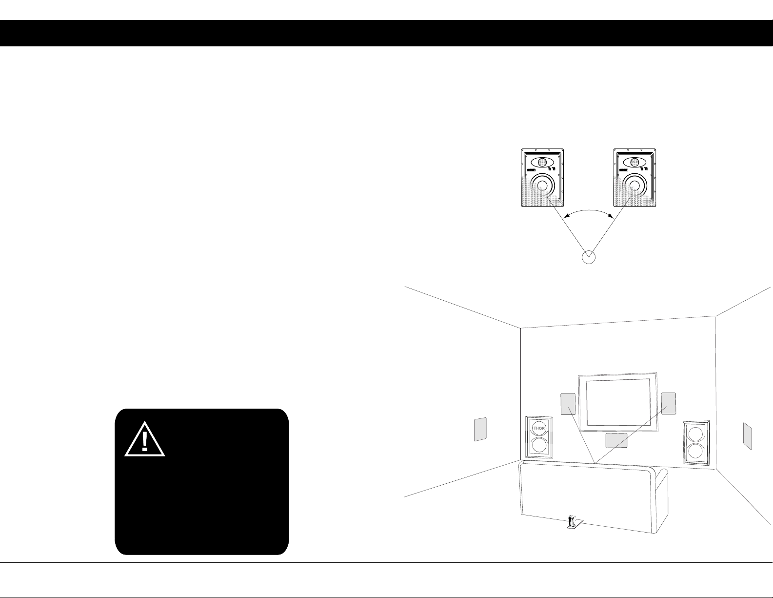
Speaker Placement:
The EWS Edgeless In-Wall Speakers are designed to be flush mounted in the walls or
ceilings. To optimize their acoustics you should follow these simple guidelines:
For best stereo reproduction the speakers should be placed an equal distance from
your listening position and separated so that the angle between them is between forty
(40) and sixty (60) degrees. The units should be placed with the tweeters near the ear
level of the seated listener.
BASS
TREBLE
+3
+3
®
0
0
-3
-3
40 - 60°
Figure 1
BASS
TREBLE
+3
+3
®
0
0
-3
-3
In-Wall Speakers
WARNING: These products are
capable of generating high
sound pressure levels. You
should exercise caution when
operating these speakers. Long
EWS800
IW-SUB10
EWS800
EWS530C
EWS800
THOR
IW-SUB10
EWS800
term exposures to high levels of
sound pressure will cause permanent damage
to your hearing. Sound pressure levels
exceeding 85dB can be dangerous with
constant exposure, set your audio system to a
comfortable loudness level. Earthquake
Sound Corporation does not assume liability
for damages resulting from the direct use of
Earthquake speakers , and urges users to play
volume at moderate levels.
2
Specifications are subject to change without notice
www.earthquakesound.com
Q10B
Tactile Transducer
Figure 2
3
Page 3

Easy Installation Steps
Specifications
LOCATE & MARK THE 2x4’s
1
Outline the hole using the supplied speaker
template - stay clear from the 2x4’s.
CUT THE DRYWALL
2
Using a drywall saw, cut out the opening.
CONNECT THE SPEAKER
3
Attach speaker wire and insert the EWS Edgeless
In-Wall speaker into the wall opening.
SECURE THE SPEAKER
4
E WS 5 3 0 C S P E CI F I C ATI O N S
Frequency Response:
Sensitivity:
Nominal Impedance:
Power Handling:
Enclosure Material / Type:
Driver Components:
Outer Dimension:
Cut Out Dimension:
Mounting Depth:
Wire Gauge Recommended:
Weight Per Speaker:
Grille Finish: White / Paintable
40Hz - 20kHz
87dB @ 1W/1M
8-Ohm
350 Watts Max
Impact resist ABS plastic
Three-way system using:
two 5.25” low mass stiff kevlar
cone midbass, one 3” low mass
kevlar cone midrange and two 1”
silk dome swiveling NEO tweeter
13 3/4” (349mm) x 9 3/4” (248mm)
12 7/8” (326mm) x 8 13/16” (224mm)
3 3/16” (85mm)
12
6.8 lbs
Align the speaker in position and tighten the
screws evenly to secure the unit.
13 3/4” (349mm) x 9 3/4” (248mm)
PLACE THE GRILLE
5
Align the grille - speaker cover - in position. Gently
snap grille into place
12 7/8” (326mm) x 8 7/8” (224mm)
Simply tighten the screws by hand using a screwdriver to prevent the
mounting ears from snapping. Some resistance may occur the first few
turns of the screw as it makes its path through the plastic.
4
Specifications are subject to change without notice
www.earthquakesound.com
3 3/16”
(85mm)
5
Page 4

Specifications
Specifications
E WS 6 0 0 S P E C IF I C ATI O N S
Frequency Response:
Sensitivity:
Nominal Impedance:
Power Handling:
Enclosure Material / Type:
Driver Components:
Outer Dimension:
Cut Out Dimension:
Mounting Depth: 3 9/16” (90mm)
Wire Gauge Recommended:
Weight Per Speaker:
Grille Finish: White / Paintable
40Hz - 20kHz
87dB @ 1W/1M
8-Ohm
350 Watts Max
Impact resist ABS Plastic
Two-way system using:
one 6.5” low mass stiff kevlar
cone midbass and one 1” silk
dome swiveling NEO tweeter
8 9/16” (217mm) x 11 15/16” (303mm)
7 7/16” (188mm) x 10 7/8” (275mm)
12
3.5 lbs
E WS 8 0 0 S P E C IF I C ATI O N S
Frequency Response:
Sensitivity:
Nominal Impedance:
Power Handling:
Enclosure Material / Type:
Driver Components:
Outer Dimension:
Cut Out Dimension:
Mounting Depth:
Wire Gauge Recommended:
Weight Per Speaker:
Grille Finish: White / Paintable
30Hz - 20kHz
88dB @ 1W/1M
8-Ohm
500 Watts Max
Impact resist ABS plastic
Two-way system using:
one 8” low mass stiff kevlar
cone midbass and one 1” silk
dome swiveling NEO tweeter
9 3/4” (248mm) x 13 3/4” (349mm)
8 13/16” (224mm) x 12 7/8” (326mm)
4 1/16” (103mm)
12
4.2 lbs
11 15/16” (303mm) x 8 9/16” (217mm)
3 9/16” (90mm)
7 7/16” (188mm) x 10 7/8” (275mm)
6 7
Specifications are subject to change without notice
www.earthquakesound.com
9 3/4” (248mm) x 13 3/4” (349mm)
4 1/16” (103mm)
8 13/16” (224mm) x 12 7/8” (326mm)
 Loading...