

Page 1

Operator's Manual
CHAINSAWS
CS3814B, CS4116B
WARNING
BEFORE USING OUR PRODUCTS, READ THIS
MANUAL CAREFULLY TO UNDERSTAND
THE PROPER USE OF YOUR UNIT.
Get parts online at www.getearthquake.com
P/N: 838184
ECN: 10304
REV6: 05/15/14
© 2014 Ardisam, Inc.
All Rights Reserved
Page 2
Operator's Manual
CS3814B, CS4116B Chainsaws
INTRODUCTION
Thank You....
for purchasing a chainsaw from Earthquake. We have worked to ensure that this chainsaw meets high standards for usability and
durability. With proper care, your chainsaw will provide many years of service. Take the time to read this manual carefully to learn
how to correctly operate and maintain your chainsaw. This manual should be considered a permanent part of your chainsaw. Due
to continuous eort to perfect our product, certain procedures and specications are subject to change without notice.
CONTENTS
Registration ........................................................................................................................................................................................................................................2
Warnings and Safety Precautions .........................................................................................................................................................................................3-11
Features .............................................................................................................................................................................................................................................12
Specications ...................................................................................................................................................................................................................................13
Assembly ...........................................................................................................................................................................................................................................14
Operation ................................................................................................................................................................................................................................... 15-16
Maintenance and Storage .................................................................................................................................................................................................... 17-20
Troubleshooting and Repair ................................................................................................................................................................................................20-21
Parts Breakdown ...................................................................................................................................................................................................................... 22-26
Declaration of Conformity ..........................................................................................................................................................................................................27
Warranty ..................................................................................................................................................................................................................................... 29-31
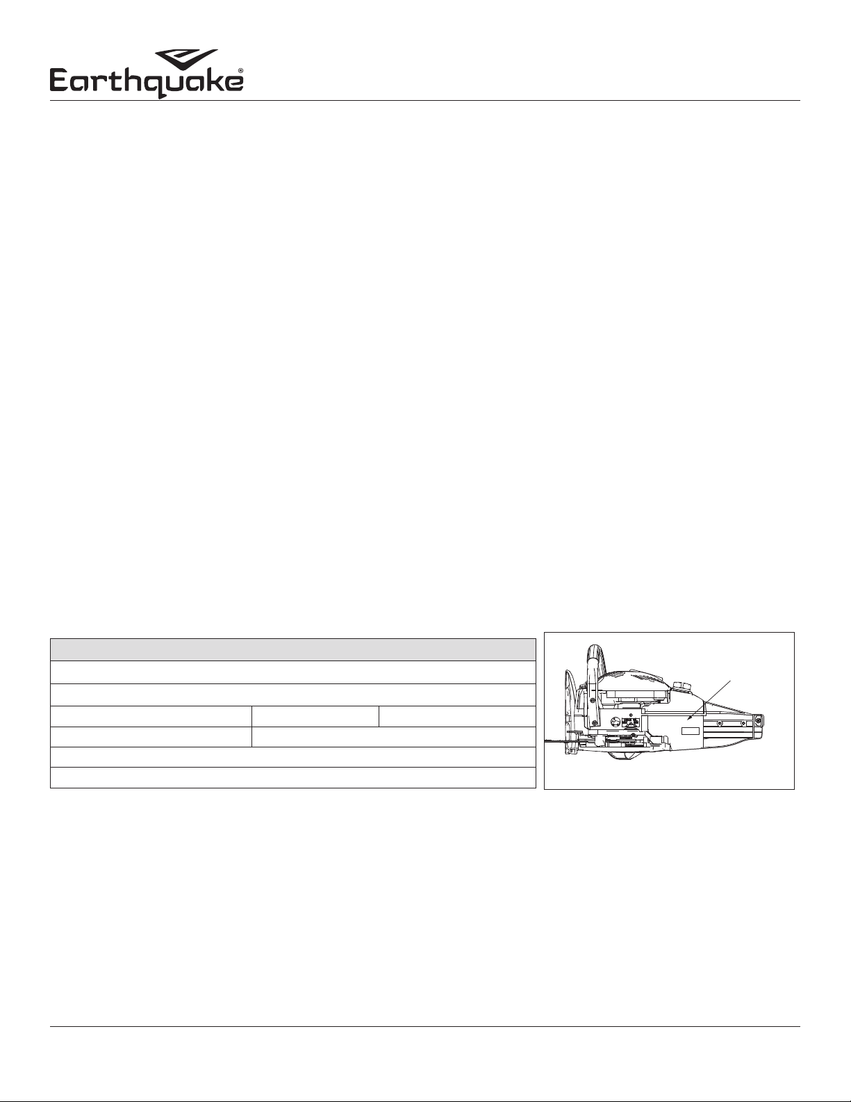
Record the model number and serial number in the space provided for easy reference. SEE FIGURE 1. Warranty is valid only if the
completed registration is received by Ardisam within 30 days of purchase. You can register your warranty online by visiting www.
getearthquake.com. If you do not have a computer, call our customer service department at (800) 345-6007 Mondays through
Fridays from 8 a.m. to 5 p.m. CST.
Registration, Service And Maintenance Log
OWNERSHIP RECORDS
Owner’s Name:
SERIAL NUMBER
Owner’s Address:
City: State/Province: Zip/Postal Code:
X0X0X0X0X0X0X0X
Model Number: Serial Number:
Date of Purchase:
Notes:
FIGURE 1
Federal Emission Information
Earthquake warrants to the retail purchaser, that this small, o-road engine was designed, built and equipped to conform at the
time of initial sale to all applicable regulations of the U.S. Environmental Protection Agency (EPA). All weights, specications, and
features are approximate and are subject to change without notice. Due to continuous product improvements, product image
may not be exact items.
This manual may contain information for several models. Read and keep this manual for future reference. This manual contains
important information on SAFETY, ASSEMBLY, OPERATION, AND MAINTENANCE. The owner must be certain that all the product
information is included with the unit. This information includes the MANUAL, the REPLACEMENT PARTS and the WARRANTIES. This
information must be included to make sure state laws and other laws are followed. This manual should remain with the engine
even if it is resold.
2
Check for parts online at www.getearthquake.com or call 800-345-6007 M-F 8-5
Page 3
WARNINGS AND SAFETY PRECAUTIONS
Operator's Responsibility
Accurate assembly and safe and eective use of the machine is
the operator's responsibility.
• Read and follow all safety instructions.
• Carefully follow all assembly instructions.
• Maintain the machine according to directions and
schedule included in this operator’s manual.
• Ensure that anyone who uses the machine is familiar
with all controls and safety precautions.
Special Safety Messages
Your manual contains special messages to bring attention to
potential safety concerns, machine damage as well as helpful
operating and servicing information. Read all the information
carefully to avoid injury and machine damage.
Operator's Manual
CS3814B, CS4116B Chainsaws
WARNING
WARNING INDICATES A HAZARD WHICH, IF NOT
AVOIDED, COULD RESULT IN DEATH OR SERIOUS
INJURY TO PERSONNEL AND/OR PROPERTY
DAMAGE.
CAUTION
CAUTION INDICATES YOUR EQUIPMENT CAN BE
DAMAGED IF THE SAFETY INSTRUCTIONS THAT
FOLLOW THIS SIGNAL WORD ARE NOT OBEYED.
IMPORTANT
INDICATES HELPFUL INFORMATION FOR PROPER
ASSEMBLY, OPERATION, OR MAINTENANCE OF
YOUR EQUIPMENT.
NOTE: General information is given throughout the
manual that may help the operator in the
operation or service of the machine.
This symbol points out important safety
instructions which if not followed could endanger
your personal safety.
Before Operating Engine:
WARNING
READ ENTIRE OPERATING AND MAINTENANCE
INSTRUCTIONS FOR THIS PRODUCT. FAILURE
TO FOLLOW INSTRUCTIONS COULD RESULT
IN SERIOUS INJURY OR DEATH. OPERATE
THE ENGINE ACCORDING TO THE SAFETY
INSTRUCTIONS OUTLINED HERE AND INSERTED
THROUGHOUT THE TEXT. ANYONE WHO USES
THIS PRODUCT MUST READ THE INSTRUCTIONS
AND BE FAMILIAR WITH THE CONTROLS.
WARNING
CALIFORNIA PROPOSITION 65 WARNING
ENGINE EXHAUST FROM THIS PRODUCT
CONTAINS CHEMICALS KNOWN TO THE STATE OF
CALIFORNIA TO CAUSE CANCER, BIRTH DEFECTS,
OR OTHER REPRODUCTIVE HARM.
WARNING
YOU MUST READ, UNDERSTAND AND COMPLY
WITH ALL SAFETY AND OPERATING INSTRUCTIONS
IN THIS MANUAL BEFORE ATTEMPTING TO SETUP
AND OPERATE YOUR MACHINE.
FAILURE TO COMPLY WITH ALL SAFETY AND
OPERATING INSTRUCTIONS CAN RESULT IN LOSS
OF MACHINE CONTROL, SERIOUS PERSONAL
INJURY TO YOU AND/OR BYSTANDERS, AND RISK
OF EQUIPMENT AND PROPERTY DAMAGE. THE
TRIANGLE IN THE TEXT SIGNIFIES IMPORTANT
CAUTIONS OR WARNINGS WHICH MUST BE
FOLLOWED.
Intended Use /
Foreseeable Misuse
This machine is a saw that utilizes a toothed, rotating chain
powered by an IC engine to be used in the cutting of cordwood. This product shall not be used for any other purpose.
Check for parts online at www.getearthquake.com or call 800-345-6007 M-F 8-5 3
Page 4

Operator's Manual
CS3814B, CS4116B Chainsaws
General Safety Rules
• Read, understand, and follow all instructions on the
machine and in the manual(s). Be thoroughly familiar
with the controls and the proper use of the machine
before starting.
• Use this equipment for its intended purpose only.
• Familiarize yourself with all of the safety and operating decals on this equipment and on any of its attachments or accessories.
• Do not put hands or feet near or under rotating parts.
• Only allow responsible individuals who are familiar
with the instructions to operate the machine. Do not
allow children to operate this machine. Do not allow
adults to operate the machine without proper instruction.
• Thoroughly inspect the area where the machine is to
be used and remove all foreign objects. Your equipment can propel small objects at high speed causing
personal injury or property damage. Stay away from
breakable objects, such as house windows, automobiles, greenhouses, etc.
• When operating the machine, wear appropriate clothing such as a long-sleeved shirt or jacket. Also wear
long trousers or slacks. Do not wear shorts. Never
wear sandals, sneakers, or open shoes, and never
operate the machine with bare feet.
• Do not wear loose clothing or jewelry. They can get
caught in moving parts. Always keep hands, feet, hair
and loose clothing away from any moving parts on
engine and machine.
• Always wear safety goggles or safety glasses with side
shields when operating the machine to protect your
eyes from foreign objects which can be thrown from
the unit. Always wear a protective hearing device.
• Always wear work gloves and sturdy footwear. Wear
footwear that will improve footing on slippery surfaces. Leather work shoes or short boots work well for
most people. These will protect the operator’s ankles
and shins from small sticks, splinters, and other debris.
• It is advisable to wear protective headgear to prevent
the possibility of being struck by small ying particles,
or being struck by low hanging branches, twigs, or
other objects which may be unnoticed by the operator.
• Do not operate the machine without proper guards or
other safety protective devices in place.
• See manufacturer’s instructions for proper operation
and installation of accessories. Only use accessories
approved by the manufacturer.
• Operate only in daylight or good articial light.
• Do not operate product when fatigued or under the
inuence of alcohol, drugs or other medication which
can cause drowsiness or aect your ability to operate
this machine safely.
• Never operate machine in wet grass. Always be sure
of your footing; keep a rm hold on the handle and
walk; never run.
• Watch for trac whenever you are operating near, or
when
crossing roads.
• If the equipment should start to vibrate abnormally,
stop the engine (motor), disconnect the spark plug
wire and prevent it from touching the spark plug.
Check immediately for cause. Vibration is generally a
warning of trouble. If the noise or vibrations of the
machine increase, stop immediately and perform an
inspection.
• Never leave the machine unattended when the engine is running. Remove the wire from the spark plug.
• Regularly inspect the machine. Make sure parts are
not bent, damaged or loose. Keep all screws, nuts and
bolts tight.
• Temperature of muer and nearby areas may exceed
150° F (65° C). Allow muer and engine areas to cool
before touching.
• Do not transport the machine from one place to another with the engine running.
• Prolonged exposure to noise and vibration from gasoline
engine-powered equipment should be avoided. Take
intermittent breaks and/or wear ear protection from
engine noise as well as heavy work gloves to reduce
vibration in the hands.
• When moving the packaged machine, always do so
with a partner.
• Check local regulations for age restrictions on use of
this machine.
Product-Specic Safety Rules
• After striking a foreign object, stop the engine.
Remove the wire from the spark plug. Inspect the
chainsaw for damage. If damaged, repair before starting and operating the chainsaw.
• The cutting chain of the chainsaw should not rotate
when the engine is idling. If it does rotate when engine is idling, contact Earthquake for instructions.
4
Check for parts online at www.getearthquake.com or call 800-345-6007 M-F 8-5
Page 5
• If an object becomes lodged in the saw, turn engine
o, remove the wire from the spark plug and secure,
allow to cool before attempting to remove the foreign
object.
• The clutch will transfer maximum power after about
two hours of normal operation. During this break-in
period clutch slippage may occur. The clutch should
be kept free of oil or other moisture for ecient
operation.
• Never cut in high wind, bad weather, when visibility
is poor, or in very low temperatures. Always check
the tree for dead branches that could fall during the
felling operation.
• Never start cutting until you have a clear work area,
secure footing and a planned retreat path away from
the falling tree.
• Always hold the chainsaw rmly with both hands
when the engine is running. Use a rm grip with
thumb and ngers encircling the chainsaw handles.
• When carrying from one place to another, always stop
the engine and hold the saw with the guide bar and
saw chain behind you and the muer away from your
body.
• Always inspect the chainsaw for worn, loose, or damaged parts. Never operate a chainsaw that has been
damaged, improperly adjusted, or is not completely
and securely assembled.
• Use extreme caution when cutting small brush and
saplings. Thinner material may be caught by the
chain and could whip back toward you or pull you o
balance.
• When cutting limbs under tension, stay alert for
“spring back” so you are not struck when the tension
in the wood bers is released.
• Always shut o the engine before setting the chainsaw down.
• Keep the handles dry, clean, and free of lubricants, oils
and fuel.
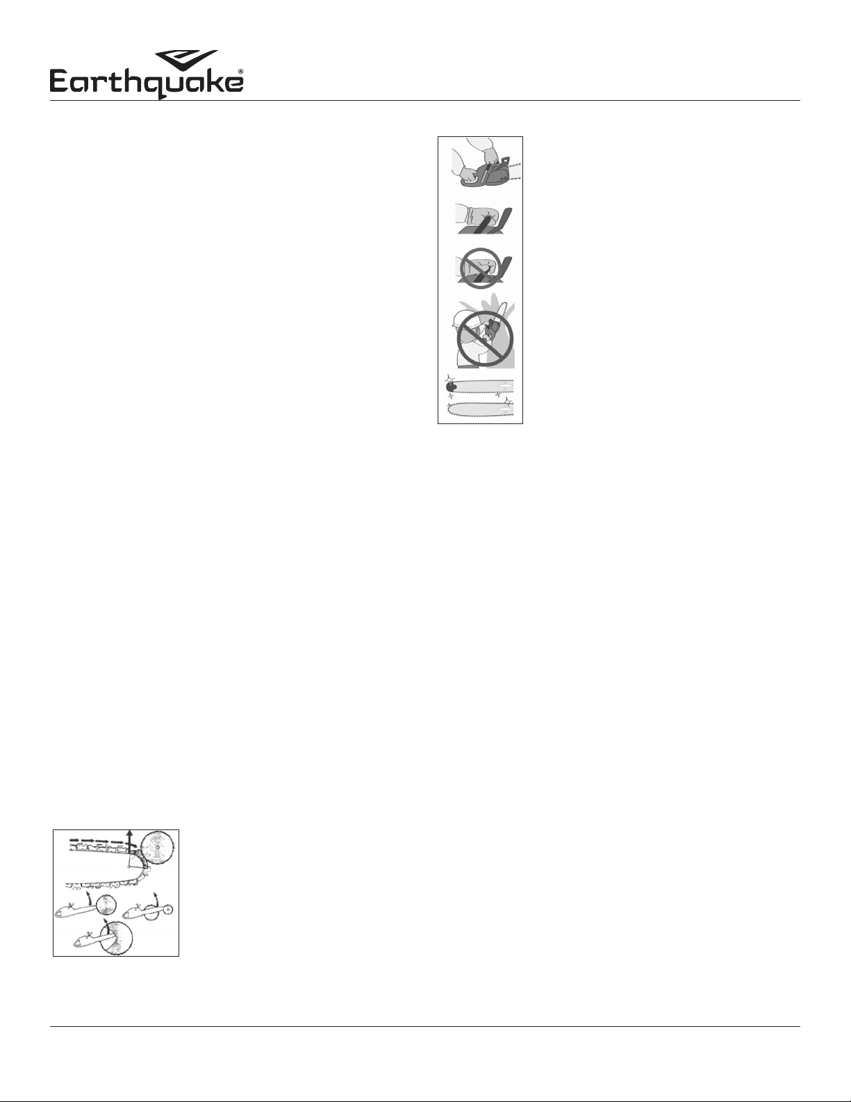
Kickback
Kickback may occur when the guide
bar nose or tip comes into contact with
a foreign object, or when the “saw kerf”
(gap in the wood being cut) closes in
on the bar and pinches the saw chain.
Operator's Manual
CS3814B, CS4116B Chainsaws
Tip contact in some cases may cause a
lightning-fast reverse action, kicking the
guide bar up and back toward the operator.
Pinching the saw chain along the top of the
guide bar may push the guide bar and the
saw unit backward toward the operator.
Either of these reactions may cause the
operator to lose control of the chainsaw,
which could result in serious personal injury
or death.
Do not rely exclusively on the safety devises
built into your saw. As a chainsaw user, it is
your responsibility to understand the inherent dangers of chainsaw use and the precautions necessary to minimize those dangers.
Precautions to Avoid Kickback:
• Always grip the chainsaw rmly with both hands; the
right hand on the rear handle, and the left hand on
the forward grip.
• Make certain the area in which you are cutting is free
from obstructions. Do not let the guide bar nose
come into contact with a log, branch, rock or other
objects while cutting. Such contact could result in a
kickback.
• Always make cuts at high engine speeds.
• Do not over-reach or cut above shoulder height.
• Always maintain a sharp and clean saw chain. Follow
manufacturer’s sharpening and maintenance instructions for the saw chain.
• Only use replacement bars and chains specied by
the manufacturer or an appropriate equivalent.
Sawing
• This saw is provided for the sole intended purpose of
cutting wood. Do not cut other materials with this
saw.
• Do not attach other tools or accessories to the output
shaft of the power unit. Doing so will void the manufacturer’s warranty.
• Do not apply excessive pressure to force the saw
through the cut. Run the engine at full throttle and
apply only light pressure.
• Always maintain a rm footing.
• Never cut from a stepladder or while in a tree.
Check for parts online at www.getearthquake.com or call 800-345-6007 M-F 8-5 5
Page 6
Operator's Manual
CS3814B, CS4116B Chainsaws
• Never use the guide bar as a means to lift, pry, move
or split objects.
• Never mount the chainsaw on a xed stand.
• If the guide bar and saw chain become pinched in a
cut, do not race the engine or pull the saw out of the
cut by force. Use a wedge or lever to open the cut
and pull the saw free.
Felling a Tree
• Felling refers to the process of cutting down a
standing tree. Numerous factors must be taken into
consideration when felling a tree. First consider the
environmental factors which will determine the felling direction:
• Wind is a major determining factor of felling direction.
• Location and number of heavy branches and the lean
of the tree.
• Ease of bucking and clean-up after felling
• Nearby standing timber in which the felled tree could
hang up.
• Location of power, telephone and data utilities, buildings, roads, bodies of water, property lines, etc.
• Wood structure and condition (i.e. rotten heartwood
or core).
• Keep all bystanders at least 2-1/2 tree lengths away
from the base of the tree to be cut. This area is considered a danger zone and must be avoided before
and during the felling operation.
Retreat Path
• Plan two (2) retreat paths away from the felling
direction of the tree. Do not retreat in the opposite
direction from the falling tree. Instead, retreat at a
45-degree angle to either side.
• Clear the retreat paths of all obstacles.
• Place all excess tools and equipment a safe distance
from the tree, but not in the retreat paths.
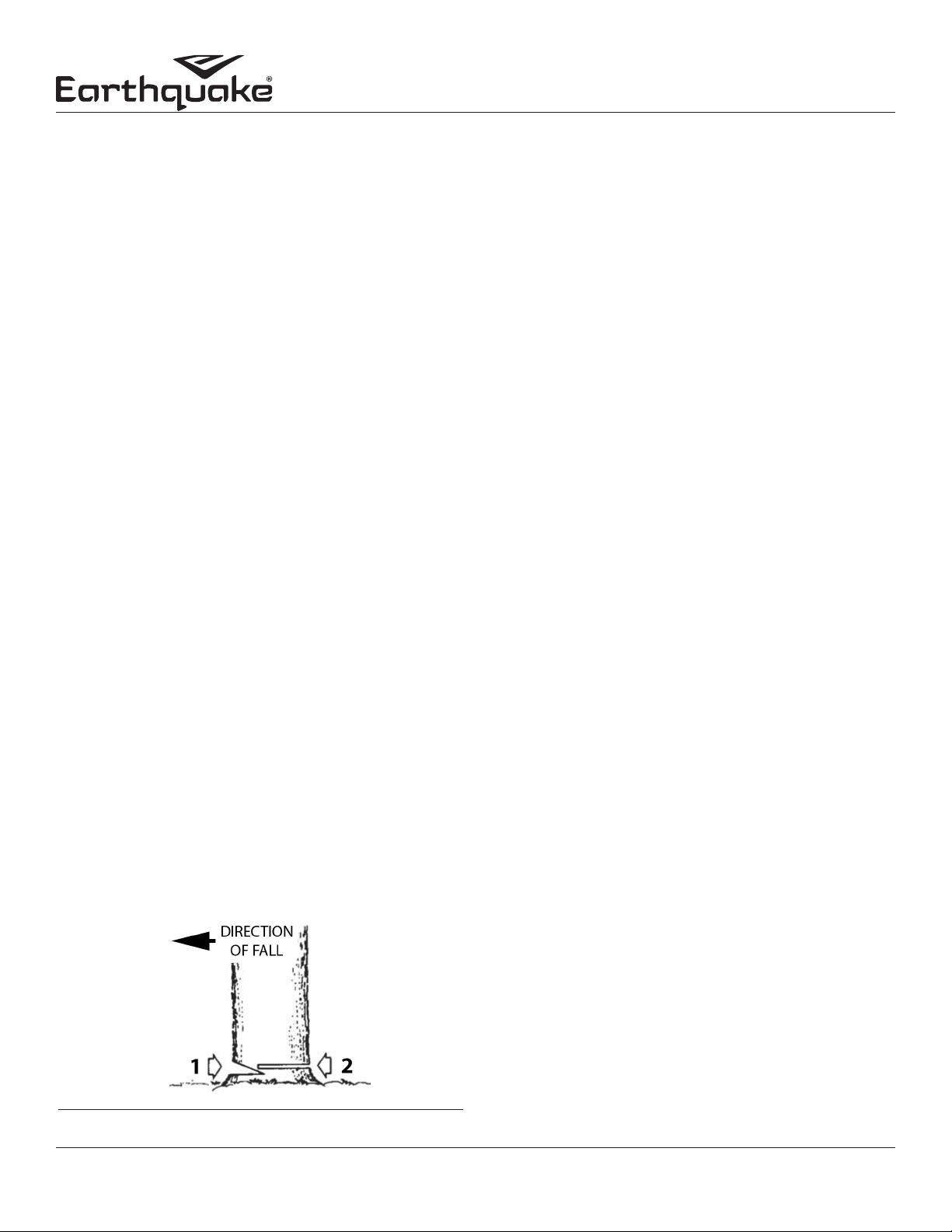
Felling Notch
The felling notch (1) is the rst cut when felling a tree. SEE FIGURE
2. The notch will act as a hinge and will direct the tree to fall in
the desired direction.
1. Begin the felling notch (1) by lining up the guide bar
perpendicular to the desired felling direction.
2. Make a downward cut at 45-degress to a depth of about
1/5 to 1/4 of the overall diameter of the tree.
3. Finish the notch by making a horizontal cut
perpendicular to the desired felling direction.
4. Remove the resultant piece.
Felling Cut
Alert others in the area of imminent danger of the falling tree.
Double check that no one has entered the area in the felling
direction. SEE FIGURE 2.
1. Begin the felling cut (2) by making a horizontal cut
perpendicular to the intended felling direction and
approximately 1-2 inches above the bottom of the felling
notch.
2. Leave approximately 1/10 of the tree’s diameter uncut.
This will form the hinge.
3. Drive plastic or wooden wedges into the felling cut to
control the fall.
4. As the tree begins to fall, alert others and immediately
evacuate the area around the tree.
Limbing a Felled Tree
“Limbing” refers to removing the limbs from a fallen tree. There is an
extremely high danger of kickback during the limbing operation. Do
not work with the nose of the guide bar, as this could cause a kickback.
Use extreme caution and avoid contact between the nose of the bar
and the log or other limbs. Do not stand on the log while limbing it as
the log may roll as limbs are removed and the center of gravity shifts.
Start limbing by removing limbs from the top side of the log,
leaving limbs on the bottom to support the log up o the ground.
Limbs under tension may pinch the guide bar and saw chain.
Shut o the engine and lift the limb to remove the bar safely.
Bucking a Log
“Bucking” is the cross-cut operation of cutting a log into usable
sections. Do not stand on the log while bucking as it may
roll. When bucking on a slope, stand uphill of the log in case it
begins to roll unexpectedly. Cut only one log at a time.
• When bucking small logs, place them in a “V” shaped
bucking horse to keep them at a working level. Never
allow a bystander to hold the log. Never hold the log
with your leg or foot.
FIGURE 2
6
Check for parts online at www.getearthquake.com or call 800-345-6007 M-F 8-5
Page 7
Operator's Manual
CS3814B, CS4116B Chainsaws
WARNING
BE CAREFUL WHEN CUTTING TREES WITH ROTTEN
HEARTWOOD THE CORE OF THE TREE. THERE
IS AN INCREASED RISK THAT THE TREE COULD
SNAP OR SPLIT UNEXPECTEDLY DURING THE CUT.
CHECK FOR DEAD OR ROTTEN LIMBS BEFORE
BEGINNING THE CUT. DEAD LIMBS CAN VIBRATE
LOOSE FROM THE TREE AND FALL, STRIKING THE
OPERATOR.
CAUTION
LOGS AND LIMBS UNDER TENSION CAN SPRING
BACK WHEN CUT LOOSE. THIS LIGHTNING FAST
ACTION COULD CAUSE A LOSS OF CONTROL OF
THE CHAINSAW.
ONLY TRAINED AND EXPERIENCED
PROFESSIONALS SHOULD FELL TREES NEAR
OVERHEAD LINES AND BUILDINGS. A SLIGHT
MISJUDGMENT OF WIND DIRECTION OR NATURAL
LEAN OF A TREE COULD RESULT IN MAJOR
PROPERTY DAMAGE.
DO NOT CUT THROUGH THE HINGE. CUTTING
THROUGH THE HINGE INCREASES THE RISK OF
LOSING CONTROL OF THE FELLING DIRECTION.
• To buck a log on at ground, make perpendicular cuts
through about half of the diameter of the log. Roll the
log and nish the cuts from the other side.
• To buck a pillowed or supported log, always make a
relieving cut through about 1/3 the diameter of the log
from the compressed side. Finish with a bucking cut
from the tension side of the log.
TIP: When cutting rewood, make sure you know the
optimum length of the nished rewood ahead of
time. Use the guide bar as an approximate length
gauge.
Pruning
Pruning is removing limbs from a standing tree, often for
purposes of maintaining a tree’s health or aesthetics. Always
work with a rm footing. Never cut from a stepladder. Do not
over reach. Do not cut above shoulder height.
1. Begin pruning by making a relief cut about 3 inches away from
the trunk of the tree to a depth of about 1/3 the diameter of the
branch.
2. Complete the cut from above, just inside of the initial relief
cut.
3. Finish pruning by making a smooth even cut nearly ush to
the trunk. It is recommended to only prune trees while they
are dormant in the fall and winter to reduce the risk posed by
disease or insects.
WARNING
ENGINES GIVE OFF CARBON MONOXIDE, AN
ODORLESS, COLORLESS, POISONOUS GAS.
CARBON MONOXIDE MAY BE PRESENT EVEN
IF YOU DO NOT SMELL OR SEE ANY ENGINE
EXHAUST. BREATHING CARBON MONOXIDE
CAN CAUSE NAUSEA, FAINTING OR DEATH, IN
ADDITION TO DROWSINESS, DIZZINESS AND
CONFUSION.
IF YOU EXPERIENCE ANY OF THESE SYMPTOMS,
SEEK FRESH AIR AND MEDICAL ATTENTION
IMMEDIATELY.
ENGINE FUEL CAN BE FLAMMABLE AND
EXPLOSIVE.
ENGINE SAFETY PRECAUTIONS
If your product comes with a separate engine manual, be
sure to read and follow all safety and warning precautions
outlined there, in addition to any in this manual.
Preventing Carbon Monoxide Poisoning
• Always start and run engine outdoors. Do not start or
run engine in an enclosed area, even if doors or windows are open.
• Never try to ventilate engine exhaust indoors. Carbon
monoxide can reach dangerous levels very quickly.
• Never run engine outdoors where exhaust fumes may
be pulled into a building.
• Never run engine outdoors in a poorly ventilated area
where the exhaust fumes may be trapped and not
easily taken away. (Examples include: in a large hole
or areas where hills surround your working area.)
• Never run engine in an enclosed or partially enclosed
area. (Examples include: buildings that are enclosed
on one or more sides, under tents, car ports or basements.)
• Always run the engine with the exhaust and muer
pointed in the direction away from the operator.
• Never point the exhaust muer towards anyone.
People should always be a safe distance away from
the operation of the engine and its attachments.
• Do not change the engine governor settings or overspeed the engine.
Gasoline Fires and Handling Fuel Safely
• When storing extra fuel be sure that it is in an appropriate container and away from any re hazards.
• Prevent re and explosion caused by static electric
discharge. Use only nonmetal, portable fuel
Check for parts online at www.getearthquake.com or call 800-345-6007 M-F 8-5 7
Page 8
CAUTION
HOT GASES ARE A NORMAL BYPRODUCT OF A
FUNCTIONING CATALYTIC CONVERTER. FOLLOW
ALL SAFETY INSTRUCTIONS TO PREVENT BURNS
AND FIRES.
DO NOT ALTER/MODIFY ENGINE:
NEVER ALTER OR MODIFY THE ENGINE FROM
THE FACTORY. SERIOUS INJURY OR DEATH MAY
OCCUR IF ENGINE IS MODIFIED OR ALTERED.
WHEN WORKING ON OR REPLACING PARTS FOR
THE ENGINE OR PRODUCT, YOU MUST ALWAYS
DISCONNECT SPARK PLUG WIRE FROM THE SPARK
PLUG AND KEEP IT AWAY FROM THE SPARK PLUG.
containers approved by the Underwriter’s
Laboratory (U.L.) or the American Society for Testing
& Materials (ASTM).
• Always ll fuel tank outside in a well ventilated area.
Never ll your fuel tank with fuel indoors. (Examples
include: basement, garage, barn, shed, house, porch,
etc.) Never ll tank near appliances with pilot lights,
heaters, or other ignition sources.
• If the fuel must be drained, this should be done
outdoors. The drained fuel should be stored in a
container specically designed for fuel storage or it
should be disposed of properly.
• Never remove the fuel cap or add fuel with the engine running. Stop engine and allow to cool before
lling.
• Do not smoke while handling fuel.
• Never drain fuel from engine in an enclosed area.
• Always wipe up excess (spilled) fuel from engine
before starting. Clean up spilled fuel immediately. If
fuel is spilled, do not start the engine but move product and fuel container from area. Clean up spilled
fuel and allow to evaporate and dry after wiping and
before starting.
• Allow fuel fumes/vapors to escape from the area
before starting engine.
• Test the fuel cap for proper installation before starting and using engine.
• Always run the engine with fuel cap properly installed on the engine.
• Do not store engine with fuel in fuel tank indoors.
Fuel and fuel vapors are highly explosive.
Operator's Manual
CS3814B, CS4116B Chainsaws
• Never pour fuel from engine fuel tank.
• Never siphon fuel by mouth to drain fuel tank.
• Always have an adult ll the fuel tank and never allow
children to ll the engine.
• Never allow an adult or anyone under the inuence of
drugs or alcohol to ll engine.
• When storing gasoline or equipment with fuel in the
tank, store away from furnaces, stoves, water heaters
or other appliances that have a pilot light or other ignition source because they can ignite gasoline vapors.
Burns and Fires
The muer, muer guard and other parts of the engine become extremely hot during the operation of the engine. These
parts remain extremely hot after the engine has stopped.
Prevention of Burns and Fires
• Never remove the muer guard from the engine.
• Never touch the muer guard because it is extremely
hot and will cause severe burns.
• Never touch parts of the engine that become hot after
operation.
• Always keep materials and debris away from muer
guard and other hot parts of the engine to avoid res.
• This engine is designed to operate using a catalytic
converter which contributes to the engine’s compliance with the EPA.
Children and bystanders
Tragic accidents can occur if the operator is not alert to the presence of children and/or bystanders. Never assume that others
will remain where you last saw them.
• Keep the area of operation clean of all persons, especially small children and pets. Keep children under
the watchful care of a responsible adult.
• Be alert and turn machine o if children enter the
area.
• Before and while moving backwards, look behind and
down for small children.
• Never allow children to operate the machine.
• Use extra care when approaching blind corners,
shrubs, trees, or other objects that may obscure vision.
8
Check for parts online at www.getearthquake.com or call 800-345-6007 M-F 8-5
Page 9

Service
• Always stop the engine whenever you leave the
equipment, before cleaning, repairing or inspecting
the unit. Engine should be turned o and cool, spark
plug wire must be removed from spark plug before
any repairs or adjustments are attempted. Never
make adjustments or repairs with the engine (motor)
running. Disconnect the spark plug wire, and keep
the wire away from the plug to prevent accidental
starting. Remove the ignition key if equipped with an
electric start.
• Always wear eye protection when you make adjustments or repairs.
• Keep all nuts and bolts tight and keep equipment in
good condition.
• Never tamper with safety devices. Check their proper
operation regularly.
• When servicing or repairing the machine, do not tip the
machine over or up unless specically instructed to do
so in this manual. Service and repair procedures can be
done with the machine in an upright position. Some
procedures will be easier if the machine is lifted on a
raised platform or working surface.
• To reduce re hazard, keep machine free of grass,
leaves, or other debris build-up. Clean up oil or fuel
spillage. Allow machine to cool before storing.
• Stop and inspect the equipment if you strike an object. Repair, if necessary, before restarting.
• Do not change the engine governor setting or overspeed the engine.
• Clean and replace safety and instruction decals as
necessary.
• To guard against engine over-heating, always have
engine debris lter mounted and clean.
• Inspect machine before storage. When not in use,
disconnect spark plug lead and store indoors in a dry
place locked or otherwise inaccessible to children.
• Use only original equipment parts from Earthquake,
including all nuts and bolts.
Operator's Manual
CS3814B, CS4116B Chainsaws
Check for parts online at www.getearthquake.com or call 800-345-6007 M-F 8-5 9
Page 10
Operator's Manual
CS3814B, CS4116B Chainsaws
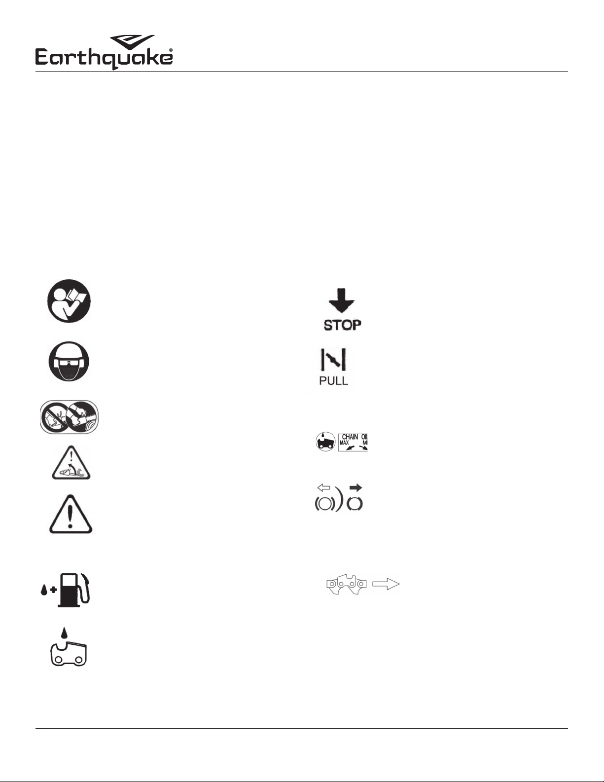
SAFETY DECALS
Reading this manual and the safety instructions it contains will provide you with the necessary basic knowledge to operate this
equipment safely and eectively. Several safety labels are placed on the chainsaw to remind you of this important information
when you operate the unit.
These important safety labels are illustrated below, and are shown here to help familiarize you with the location and content of the
safety messages you will see as you perform normal cutting operations. Review these labels now. If you have any questions regarding their meaning or how to comply with these instructions, reread the complete safety instruction text on the preceding pages, or
contact your local dealer.
Should any of the safety labels become unreadable because of being worn, faded, or otherwise damaged during the use of your
chainsaw, use the part number information provided to order a replacement label from your local authorized dealer.
The safety labels are easily applied, and will act as a constant visual reminder to you, and others who may use the equipment. Follow
the safety instructions necessary for safe, eective operation of your chainsaw.
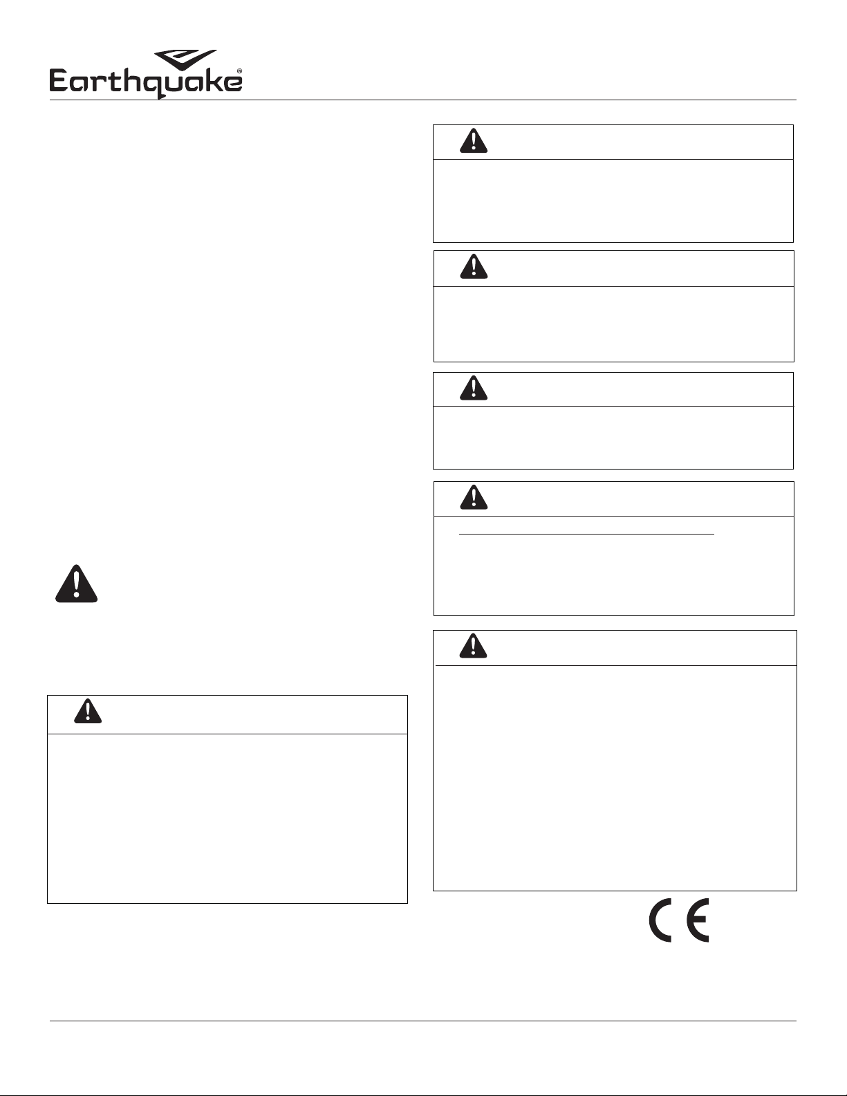
(1) Read operator’s instruction book
before operating this machine.
(2) You must wear appropriate ear, eye,
and head protection.
(3) Use two hands when operating the
chainsaw.
(4) Warning! Danger of kickback.
(5) Read, understand and follow all
warnings.
For safe operation and maintenance, additional symbols
are engraved on the machine.
(6) Indicates the port for refueling the
gas/oil mixture.
Location: Near the fuel cap.
(7) Indicates the port to rell the chain
oil.
Location: Near the oil cap
(8) Indicates the engine operation ON/OFF
switch. Flipping the switch to the “O”
position immediately stops the engine.
Location: Near the rear at the left side of
the rear handle.
(9) Indicates the choke knob location. Pull
out the choke knob and the choke closes;
push in the choke knob and the choke
opens. (Sets High Idle.)
Location: Near the rear at the right side of the
rear handle.
(10) Indicates the oil pump adjustment location.
Turn the rod using a screwdriver and follow
the arrow to the MAX position to increase
chain oil ow. Turning the rod to the MIN
position decreases chain oil ow.
Location: Bottom of the power unit.
(11) Indicates the directions that the chain
break is released (white arrow) and activated (black arrow)
Location: Front of the chain cover.
(12) Indicates the direction of the saw chain in-
stallation.
Location: Front of the chain cover.
10
Check for parts online at www.getearthquake.com or call 800-345-6007 M-F 8-5
Page 11

110
CE MODEL SAFETY WARNINGS AND MARKINGS FOR EUROPEAN MODELS
The following markings and labels are applied to the product, in addition to those shown in the original instructions.
A B C
D E F G
Decal Descriptions:
A: WARNING!
B: WARNING! Danger of kickback
Operator's Manual
CS3814B, CS4116B Chainsaws
H
Apprêt à Combustible
Fuel Primer
19716
C: Use two hands while operating chainsaw
D: Read operator instructions
E: Always wear protective head, eye, and ear gear
F: Always wear protective gloves when using product
G: Always wear protective foot gear when operating unit
H. Fuel Primer
NAMEPLATE DECALS
ARDISAM, INC.
1160 8th Avenue | Cumberland, WI 54829 | USA
Model: CS38 Type: Chain Saw
Year: Mass: 5.3 kg
Max. Operating Speed: 11,000 rpm
10806
Decal Description:
Pull recoil out slightly
before giving a full arm
pull.
ARDISAM, INC.
1160 8th Avenue | Cumberland, WI 54829 | USA
Model: CS41 Type: Chain Saw
Year: 2012 Mass: 5.3 kg
Max. Operating Speed: 11,000 rpm
Decal Description:
Guaranteed noise level
decal
10807
Check for parts online at www.getearthquake.com or call 800-345-6007 M-F 8-5 11
Page 12

Operator's Manual
BREAK ON
BREAK OFF
CS3814B, CS4116B Chainsaws
SAFETY FEATURES
This saw is equipped with certain safety features and devices
to protect the user from harm in the event the saw reacts
unexpectedly to external forces:
1. Chain Brake: The saw is equipped with a chain brake
designed to stop the chain instantaneously upon
activation. The chain brake can be activated in one of
two ways:
• The forward hand guard doubles as an activation
lever for the hand brake. It can be activated manually,
or it may be activated by the user’s arm if a kickback
occurs.
• The saw is also equipped with an “Inertial Chain
Break.” The same mechanism as above is activated by
the inertial force created when a counterweight under
the forward hand guard accelerates toward the bar
nose during a kickback.
• Proper cleaning and care of the chain brake system
are required to ensure reliable operation in the eld.
You should also check your chain brake for proper
operation regularly. To check your chain brake:
• Manually activate the chain brake by pushing the
forward hand guard toward the bar nose (SEE
FIGURE 3-A). There will be an audible click when the
chain brake engages. If there is no audible click, the
chain brake may already be engaged. Pull back on
the forward hand guard to deactivate the brake (SEE
FIGURE 3-B). An audible click should be heard when
the brake disengages. If there is still no audible click,
the brake is not functioning properly. Remove the
clutch cover, clean and reassemble, and re-test. If no
audible click is heard, contact customer service for
further assistance.
• With the saw’s engine shut o and the chain brake
disengaged, rmly grasp both handles and hold the
saw over a log or low stump. Swing the bar nose
sharply down until it makes contact. This should
create enough inertial force to automatically activate
the chain brake. When the chain brake engages, an
audible click should be heard. If no audible click is
heard, the brake is not functioning properly. Remove
the clutch cover, clean and reassemble, and re-test. If
no audible click is heard, contact customer service for
further assistance.
2. Throttle Interlock: This saw is equipped with a throttle
interlock designed to prevent accidental engagement of
the throttle control. The throttle interlock is disengaged
by depressing the red tab on top of the rear handle. This
is usually accomplished when the user grasps the rear
handle to operate the saw.
3. Chain Catcher: Each saw is equipped with a chain
catcher beneath the clutch cover. If the chain is ever
thrown from the guide bar, or if the chain breaks, the
chain catcher is designed to capture the chain and
prevent it from whipping back toward the operator.
NOTE: Inspect the chain catcher before each use. Replace
if missing or badly damaged.
4. Kickback Reduction Guide Bar and Saw Chain: This
saw has been equipped with a Double Guard® 91 guide
bar and 91P S-Series Low Kickback saw chain by Oregon®.
The features of this bar and chain combination are design
to reduce the risk of kickback. To maintain adequate
kickback prevention, only use these components
when replacing guide bar or saw chain. (Refer to the
Maintenance section of this manual for full details.)
A - chain break ON
B - chain break OFF
NOTE: Chain break must be in the OFF position to run the
chainsaw.
FIGURE 3
Check for parts online at www.getearthquake.com or call 800-345-6007 M-F 8-5 12
Page 13

FEATURES
Operator's Manual
CS3814B, CS4116B Chainsaws
13
11
12
1
10
2
3
4
5
6
9
78
13
1
14
1. Front hand guard And chain brake cover 6. Rear handle 11. Front handle
2. Starter handle 7. Throttle trigger 12. Saw chain
3. Air lter cover 8. Engine switch 13. Guide bar
4. Choke knob 9. Fuel tank cap 14. Primer Bulb
5. Throttle trigger lock-out 10. Oil tank cap
Check for parts online at www.getearthquake.com or call 800-345-6007 M-F 8-5
Page 14

Operator's Manual
CS3814B, CS4116B Chainsaws
SPECIFICATIONS
SPECIFICATIONS
Displacement 37.2cc (CS3814B)
40.1cc (CS4116B)
Fuel mixture Mixture (Unleaded Gasoline, 50: two-cycle oil 1)
Fuel type Minimum 87 octane gasoline with NO ethanol content
NOTE: If using an ethanol blended fuel, a fuel stabilizer, mixed to
manufacturer specications, is recommended
Engine Oil Engines are lubricated by Viper Engine Oil Part No. 16890 specially
formulated for air-cooled 2-cycle gasoline engine use. If oil is not
available, use an antioxidant added quality oil expressly labeled for
air-cooled 2-cycle chain saw engine use.
Fuel tank capacity 310 ml
Chain oil Bar chain oil for proper season
Oil tank capacity 210 ml
Carburetor Diaphragm type
Fuel consumption at maximum engine power 560 g/kw.h
Idling speed 3000 rpm max / rpm +/- 150
Maximum speed with cutting attachment 11,000 r/min
Ignition system CDI with timing advance function
Spark Plug Torch L8RFT, Champion RCJ7Y or NGK BPMR7A
Oil feeding system Mechanical plunger pump with adjuster
Sprocket Teeth x Pitch 6T x .375”
Dimensions (L x W x H) 710-76 x 235 x 240 mm
28” - 30” x 9.25” x 9.5”
Dry weight (without guide bar and chain, empty tanks 9.26 lb
Guide Bar Type Sprocket Nose
Guide Bar Size 14” (CS3814B) Oregon® 140SDEA041
16” (CS4116B) Oregon® 160SDEA041
Saw Chain Type Oregon® 91VG or 91P S52 (CS3814B)
Oregon® 91VG or 91P S57 (CS4116B)
Pitch 3/8” Low Prole
Gauge 0.050”
Specications are subject to change without notice.
This saw is intended primarily for the consumer or occasional user as dened in ANSI B175.1.
SOUND AND VIBRATION LEVELS
Model 2006/42/EC Operator Ear
LPA (dBA)
2006/42/EC Sound Power Level
LWA (dBA)
2006/42/EC Hand/Arm Vibration
Max m/s
CS3814B 100 110 10.5
CS4116B 100 110 10.5
CS4518B 102 110 12.5
Sound levels tested in accordance with ISO3744 & ISO 11201 - Grade 2 (Engineering ) Method. Readings taken with engine at full throttle.
EAV = Exposure Action Value, ELV = Exposure Limit Value
Check for parts online at www.getearthquake.com or call 800-345-6007 M-F 8-5 14
2
Page 15

ASSEMBLY
The Earthquake chainsaw carton includes the following
• Power Unit: Pre-assembled engine, handles, fuel tank,
oil tank, and chain brake handle.
• Guide Bar: Oregon® Double Guard 18”.
• Saw Chain: Oregon® 91VG or 91P S62
• “Scwrench” Multi-tool: Combination plug/bar wrench
and screwdriver
• Bar Scabbard: Plastic guard that ts over the guide bar
and saw chain.
• 5/32 inch round chain le
• Bar and chain have been installed for your
convenience.
Bar and Chain Removal and Assembly
1. Place the power unit on a at, stable work surface with
the muer facing to your right.
2. Pull back (toward the forward handle) on the chain brake
lever to ensure that the chain brake is disengaged.
3. Using the “Scwrench” multi-tool, loosen and remove the
bar nuts securing the clutch cover to the power unit. Set
the clutch cover aside. Tip: If working in the eld, place the
bar nuts in the clutch cover to keep from losing them in
grass or foliage.
4. Install the guide bar on the bar studs, and slide the bar
back until it comes into contact with the drive sprocket.
5. Protective gloves should be used when handling the
chain. Carefully remove the saw chain from its package.
Stretch the chain out into a long horizontal loop. The
cutting teeth on the top length of chain should face
away from the power unit. The cutting teeth on the
bottom length of the chain should face toward the power
unit.
6. Wrap the chain around the drive sprocket rst, and lay
the drive links of the chain into the groove along the
outer perimeter of the guide bar. Lay the chain over the
nose (tip) of the guide bar.
7. Slide the bar forward until the bar mates with the
tensioning tab. Make sure that the drive links of the
chain are seated within the groove around the perimeter
of the bar. If the bar will not slide forward far enough, use
the screwdriver end of the Scwrench to turn the tension
screw counter-clockwise. The tension screw is located on
the front of the power unit, next to the guide bar.
Operator's Manual
CS3814B, CS4116B Chainsaws
WARNING
FAILURE TO PROPERLY TENSION THE CHAIN
COULD RESULT IN DAMAGE TO THE UNIT OR
SEVERE INJURY OR DEATH. OVER TENSIONING
COULD CAUSE DAMAGE TO THE SAW’S POWER
UNIT OR GUIDE BAR. LACK OF TENSION COULD
CAUSE THE CHAIN TO DISENGAGE THE BAR
COMPLETELY, ALLOWING IT TO WHIP BACK
WHERE IT COULD CONTACT THE OPERATOR
CAUSING SEVERE INJURY OR DEATH.
NOTE: Make sure the chain brake is OFF.
8. Replace the clutch cover over the bar, and turn the bar
nuts onto the bar studs. Only nger tighten the bar nuts at
this step.
9. Locate the tension screw on the front of the power unit
next to the guide bar. Use the Scwrench to turn the
tension screw clockwise. This will take the slack out of
the saw chain. When properly tensioned, two conditions
must be met:
• The chain should not hang or droop away from the
guide bar.
• You should be able to pull the chain slightly away from
the guide bar, but not so far as to be able to disengage
the drive links from the groove around the perimeter of
the bar.
10. Pull up on the guide bar’s nose and use the Scwrench to
tighten the bar nuts. Check that the chain spins freely
around the bar by hand. If there is resistance, the chain
may be too tight.
11. Place the bar scabbard over the guide bar and saw chain.
This guard will help to protect the user from the sharp
cutting teeth as well as help keep the cutting teeth sharp
when the saw is not in use.
12. Check the tension of the saw chain frequently during
use, especially during the rst two hours of use on a new
chain. Re-tension as needed.
13. Always release the tension in the chain after nishing
work and before the saw chain and guide bar cool
completely. As the saw chain heats up during operation,
it will expand and stretch, requiring re-tensioning on
occasion. As the saw cools down the saw chain will
shrink, and if left tensioned, could cause severe and
permanent damage to the guide bar or the power unit’s
drive components.
15
Check for parts online at www.getearthquake.com or call 800-345-6007 M-F 8-5
Page 16

Operator's Manual
CS3814B, CS4116B Chainsaws
OPERATION
Filling Fuel Tank
1. Shut o engine and allow engine to completely cool
before relling the fuel tank.
2. Move to a well-ventilated area, outdoors, away from
ames and sparks.
3. Clean debris from area around the fuel cap.
4. Loosen fuel cap slowly.
5. Carefully add fuel without spilling.
Note: Use a minimum 87 octane gasoline with NO
ethanol content (50:1 mixture). If using an
ethanol blended fuel, a fuel stabilizer, mixed to
manufacturer specications, is recommended.
6. Do not ll gas tank completely full; allow space for fuel to
expand.
7. Immediately replace fuel cap and tighten. Wipe o
spilled fuel and allow to dry before starting engine.
The saw chain needs to stay lubricated during operation of
the unit. Aside from the fuel reservoir on the chainsaw, there
is also a bar and chain oil reservoir. Use only oil that has been
designed specically for use with chainsaws. Bar and chain oil
has chemical properties which allow it to adhere to the saw
chain and provide better lubrication while the chain is in motion.
The saw is equipped with an adjustable automatic oiler.
The oiler and oil reservoir are designed such that a full tank of
fuel will run out before a full tank of oil. This ensures that the
bar and chain will receive a constant ow of oil during operation. Always top o your oil reservoir when re-fueling.
To adjust the automatic oiler you must rst locate the oiler
screw positioned on the under-side of the chainsaw (SEE
FIGURE 4). Turn the screw counter-clockwise to increase and
clockwise to decrease oil ow.
NOTE: It is recommended for the use of your chainsaw to
leave the automatic oiler on full ow.
Filling the Bar and Chain Oil Reservoir
1. While the engine is cool for re-fueling, clean debris from
area around the bar and chain oil cap.
2. Loosen oil cap slowly.
3. Carefully add bar and chain oil without spilling.
4. Do not ll oil reservoir completely full; allow space for oil
to expand.
5. Replace cap and tighten. Wipe o any spilled oil before starting
engine.
NOTE: Do not use waste or recycled oil. Waste or recycled
oil could contain contaminants which will cause
damage to the oil pump.
WARNING
CHAIN BRAKE WILL NOT PREVENT A KICKBACK.
IN THE EVENT OF A KICKBACK, THE CHAIN BRAKE
IS DESIGNED TO REDUCE THE RISK OF INJURY TO
THE OPERATOR.
DO NOT MODIFY OR ALTER THE FUNCTIONALITY
OF THE THROTTLE INTERLOCK IN ANY WAY. DOING
SO WILL ALLOW ACCIDENTAL ENGAGEMENT
OF THE THROTTLE WHICH WILL RESULT AN
UNEXPECTED OPERATION OF THE SAW CHAIN.
CHAIN CATCHER IS INTENDED TO PREVENT INJURY
IN THE EVENT OF A CHAIN MALFUNCTION. NEVER
OPERATE A SAW WITHOUT A CHAIN CATCHER.
REPLACE IF MISSING OR BADLY DAMAGED.
X0X0X0X0X0X0X0X
ADJUSTABLE
OILER SCREW
FIGURE 4
Check for parts online at www.getearthquake.com or call 800-345-6007 M-F 8-5 16
Page 17

Pre-Start Inspection
1. Check that all safety guards are in place and all nuts and
bolts are secure.
2. Inspect air cleaner for cleanliness.
3. Check the fuel supply. Fill the fuel tank no closer than 1/2”
from top of tank to provide space for expansion.
4. Check the bar and chain oil level.
5. Be sure spark plug wire is attached and spark plug is
tightened securely.
6. Examine underneath and around engine for signs of oil or
fuel leaks.
7. Inspect fuel hoses for tightness and fuel seepage.
8. Look for signs of engine damage.
9. Remove excessive debris from muer area and recoil
starter.
Start-Up
Before starting the engine, inspect the immediate area. Check
that there are no bystanders nearby. Make sure that you have
a rm and stable footing and remove tripping hazards. Clear
all objects that the saw chain could catch on and cause a pullin, push-back, or kickback reaction.
There are two safe and approved positions for cold-starting.
Starting on the ground:
1. Place saw on a at, stable patch of ground free of
vegetation and check that the saw chain is not in contact
with the ground.
2. Place right foot on the base of the rear handle and rmly
grip the forward handle with left hand.
Starting In A Raised, Standing Position:
1. Place the rear handle between knees or thighs and rmly
grip the forward handle with left hand.
Cold Engine Start Procedure:
1. Set the chain brake to the ON position by pulling the
front hand guard away from the front handle.
NOTE: See the Safety Features section for more
instruction on how to engage and disengage the
chain brake.
2. Grip the rear handle with right hand, depressing the
throttle interlock with right palm, and pull the throttle
control to check for smooth operation.
3. Push the primer bulb until it lls with fuel (3-4 pushes).
Operator's Manual
CS3814B, CS4116B Chainsaws
WARNING
DO NOT RUN A SAW THAT IS NOT PROVIDING PROPER
OIL COVERAGE UNDER ANY CIRCUMSTANCES. DOING
SO WILL RESULT IN PERMANENT DAMAGE TO THE
GUIDE BAR AND SAW CHAIN.
4. Put the power unit’s ignition switch in the ON position.
NOTE: The ON position is when the toggle switch is up.
5. Pull the choke all the way out to the CHOKE position.
NOTE: This will close the choke and set throttle to high
idle.
6. Pull starter rope 1-4 times. DO NOT pull more than 4
times. After pull 4, push the choke in without touching
throttle (this maintains the throttle in high idle). Pull
starter rope an additional 1-4 times with the choke
pushed all the way in. The engine should start. If engine
does not start, continue with Step 5 of Cold Engine Start.
Failure to follow these starting instructions may cause
your engine to ood.
NOTE: Proper starting form begins with grasping the
starter handle rmly with right hand and slowly
pull until it provides resistance. Without letting
the starter handle retract, pull rope with a rapid
full arm stroke. Let it return to its original position
very slowly until unit res or starts. Repeat this
technique ever time the starter rope is pulled.
7. After engine starts running, depress throttle interlock
with right palm and pull throttle control with right index
nger.
NOTE: This will automatically reset the choke to the RUN
position and disengage high idle and go to normal
idle.
8. Release the chain brake. To set the chain brake to the OFF
position, push the front hand guard towards the front
handle.
Warm engine Start Procedure:
1. Put ignition switch in the ON position.
2. Pull the choke all the way out.
3. Push choke all the way back in without touching throttle
(this sets throttle to high idle).
4. Pull starter rope 1-4 times, engine should start. If engine
does not start, continue with Step 5 of the Cold Engine
Start.
17
Check for parts online at www.getearthquake.com or call 800-345-6007 M-F 8-5
Page 18

Operator's Manual
CS3814B, CS4116B Chainsaws
Hot Engine Start Procedure:
1. Put ignition switch in the ON position.
2. Pull rope 1-2 times to start.
3. If engine does not re, refer to Warm Engine Start.
Stopping The Engine:
1. Let the saw idle for up to one minute to continue blowing
air through the engine to aid the cool-down process.
Doing so will help prolong the life of the saw.
NOTE: The engine is still running. Always maintain a rm,
controlling grip on the unit while the engine is
running.
2. Put the unit’s ignition switch in the OFF position.
3. Once cooled down and o, remove tension from the
chain.
Maintenance Item Every Refueling
Check Engine and Check Hardware
MAINTENANCE AND STORAGE
Good maintenance is essential for safe, economical, and
trouble-free operation. It will also help reduce air pollution. To
help you properly care for your engine, the following pages include simple maintenance procedures using basic hand tools.
Other service tasks that are more dicult, or require special
tools, are best handled by professionals and are normally performed by a technician or other qualied mechanic.
NOTE: Maintenance, replacement or repair of the
The maintenance schedule applies to normal operating conditions. If you operate your engine under unusual conditions
(such as sustained high-load or high-temperature operation) or
use it in unusually wet or dusty conditions, consult your servicing dealer for recommendations applicable to your individual
needs and use.
X x
emissions control devices and systems may
be performed by any non-road engine repair
establishment or individuals. However, items must
be serviced by an authorized dealer to obtain “no
charge” emissions control service.
Every 8
Hours
Every 20
Hours
Each Year
Air Filer
(See Air Filter Section)
Spark Plug
(Gap 0.025” or 0,0635mm)
See Spark Plug Section
Chain Tension Check/Adjust
Chain
(See Chain Sharpening Section)
Guide Bar
(See Check Guide Bar Section)
Oiler Port Clean
Drive Sprocket
(See Drive Sprocket Section)
Check x
Clean X X
Replace X X
Check/Adjust
Replace X
Check/Sharpen
Clean X
Replace X
Check X
Clean x
Check/Clean
Grease
x
x
X
X
X X
X X
Check for parts online at www.getearthquake.com or call 800-345-6007 M-F 8-5 18
Page 19

Operator's Manual
CS3814B, CS4116B Chainsaws
BAR AND CHAIN OIL
The saw is equipped with an adjustable chain oiler. The oil
pump, driven by the drive sprocket, will only pump oil when
the engine is running at high enough speeds to engage the
clutch and rotate the chain. Furthermore, the ow of oil is
adjustable to accommodate variations in chain oil due to
temperature.
To adjust the oil pump, insert a screwdriver in the small notch
beneath the clutch and drive sprocket. To increase the ow of
oil, turn the screwdriver counter-clockwise. To decrease the
ow of oil, turn the screwdriver clockwise. For optimum performance, use a higher rate of ow with thicker oil or in colder
temperatures, and a lower rate of ow with thinner oil or in
warmer temperatures.
The guide bar and saw chain need to be well lubricated during operation to prevent permanent damage from friction
and heat. Be sure to check the oil supply to the bar and chain
before use.
1. After starting the engine, hold the saw up with the chain
suspended in front of or above a test surface.
2. Run the engine at about half throttle.
3. Oil should be ung o of the rotating chain onto the test
surface.
If the saw chain seems dry, but there is some oil present on the
bar or test surface, the oil pump may be set too low. Increase
the setting by turning the adjustment screw, located on the
under-side of the saw, counter-clockwise (SEE FIGURE 4). If
the saw chain and guide bar are dry and there is no oil on the
test surface, the oiler port and guide bar may need cleaning.
Remove the clutch cover, bar, and chain, and clean under the
clutch cover with a brush and clean the guide bar with a wire
or small screwdriver.
Reassemble and retest for oil presence. If no oil is present after
adjusting the oiler setting and cleaning the oiler port, the oil
pump may not be functioning. Discontinue use of the unit
and contact your local authorized service center or customer
service for assistance.
In compliance with EPA regulations, any adjustments to the
carburetor must be made by an authorized service center. An
authorized service center is capable of troubleshooting carburetor problems, adjusting carburetors to perform correctly, and
adjusting carburetors to compensate for altitude.
ENGINE MAINTENANCE
Cooling Fins
1. Cooling ns, air inlets, and linkages must be free from any
debris before each use.
Air Filter
1. Never run engine without air cleaner properly installed.
Added wear and engine failure may occur if air cleaner is not
installed on engine.
2. Service air cleaner every 3 months or after 20 hours
of operation. Clean lter daily in extremely dusty
conditions.
Steps for Cleaning Air Filter
1. Remove the air cleaner cover by turning the thumb screw
on top of the power unit counter-clockwise and lifting the
cover o.
2. To remove the lter, lift the lter element o of the threaded
stud.
3. Larger surface dust and dirt particles can be removed from the
lter element by lightly tapping a corner of the lter against a
hard surface.
4. To clean ner dust trapped in the mesh screens, split the
lter by inserting a at screwdriver between the dogs on
one corner of the lter element and twisting.
5. Using an air compressor at a low pressure or a store-bought
compressed air duster, blow air through the mesh from the
inside.
6. Press the two lter halves back together by squeezing around
the rim. Do not place pressure on the mesh or a puncture
could occur.
7. Place the lter back over the threaded rod, making sure
to seat the lter on the O-ring on the carburetor.
8. Place the air cleaner cover back on the saw body and turn
the thumb screw clockwise until nger tight.
NOTE: Carburetor is set at factory. Further adjustment
must be performed by an authorized service center.
Contact customer service for a list of authorized
service centers.
19
Check for parts online at www.getearthquake.com or call 800-345-6007 M-F 8-5
Page 20

Operator's Manual
CS3814B, CS4116B Chainsaws
Spark Plug
The recommended spark plug is a NGK BPMR7A, Champion
RCJ7Y, or Torch L8RFT.
Steps for Removing the Spark Plug
1. Remove the air cleaner cover by turning the thumb screw
on top of the power unit counter-clockwise and lifting the
cover o.
2. Disconnect the spark plug cap and clean any debris from
around the spark plug area.
3. Remove spark plug using the “Scwrench” multi-tool.
Replace if any of the following occur; pitted electrodes,
burned electrodes, cracked porcelain, or deposits around
the electrodes.
4. After analysis, seat spark plug and hand turn until nger
tight.
Installing Spark Plug
1. Reinstall original spark plug, tighten additional 1/2 turn.
2. Installing new spark plug, adjust spark plug gap to 0.025”
(0,635mm) and tighten additional 1/8 – 1/4 turn.
NOTE: Loose spark plug may overheat and damage
engine. Over tightened spark plug may damage
threads in the cylinder head.
Carburetor
NOTE: Never tamper with the factory setting of the
carburetor.
Saw Chain Tension Maintenance
Keeping the saw chain at the proper tension is necessary for safe
operation and will help prolong the life of the saw chain and the
guide bar. Never tighten a warm/hot chain.
1. Shut the power unit o and allow the saw to cool.
2. The saw chain should not hang down from the bottom
edge of the guide bar.
3. Wearing protective gloves, hold the guide bar with one
hand and pinch the chain with the free hand.
4. Pull down on the chain. It should pull away from the
bar, but the drive links should not disengage the groove
around the perimeter of the guide bar.
5. Add or remove tension as needed with the adjustment
screw at side of bar.
6. Hold up on the guide bar nose and tighten the bar nuts
with the Scwrench.
• Add tension at the beginning of every work session.
• Check tension at every re-fueling.
• Remove tension at the end of every work session.
Saw Chain Maintenance
Keeping the saw chain sharp is a critical component to operating a chainsaw. A dull saw chain will drastically reduce cutting
eciency and can pose certain safety hazards.
• Avoid unintentionally striking foreign objects. This
can cause a kickback, but will also reduce the sharpness or permanently damage the saw chain.
• Avoid cutting wood that has been drug on the
ground. Sand, dirt, and mud stuck to the log will dull
the saw chain.
• Avoid cutting wood that may contain metal such as
nails, staples, or wire.
• Avoid cutting all the way through when bucking a
log. This could allow the chain to come into contact
with the soil below, dulling the saw chain.
Sharpening Saw Chain Cutters (Teeth)
The saw chain included with this saw is a 91VG Chamfer
Chisel™ or 91P Chamfer Chisel™ and requires a 5/32 inch round
le (included in the original packaging).
When to have your saw chain sharpened:
• Sawdust becomes powder-like
• You need to force the saw into the cut
• The saw tends to cut through at an angle instead of
making a straight cut
• Vibration increases
• Fuel consumption increases
Always inspect your saw chain prior to use and sharpening.
Check for the following:
• Bent or burred drive links
• Broken cutters or tie-straps
• Loose rivets or broken rivet heads
• Dull, nicked, or damaged cutters.
If broken components are found, discard the chain immediately.
To properly sharpen you saw chain:
1. Be sure to have the correct size le and le guide.
2. When hand ling it’s important that 1/5, or 20 percent,
of the le’s diameter is always held above the cutter’s top
plate.
3. Keep the correct top-plate ling angle line on your le
guide parallel with the chain.
4. Sharpen all cutters on one side of the chain rst. Sharpen
by ling from the inside of each cutter to the outside.
After sharpening the rst side, turn the saw around and
repeat the process for cutters on the other side of the
chain.
Check for parts online at www.getearthquake.com or call 800-345-6007 M-F 8-5 20
Page 21

Operator's Manual
CS3814B, CS4116B Chainsaws
5. If the chrome surface of the top or side plates is
damaged, le back until such damage is removed.
6. Keep all cutters at an equal length. Begin ling on the
cutter with the most damage, and le all subsequent
cutters to the same length.
7. DO NOT alter or le the tops of bumper tie strap links
(between each cutter) on the 91VG chain.
8. File ONLY on the “Push” stroke, do not pull the le against
any metal object as this will damage the le.
It is also important to maintain the depth gauge setting
throughout the lifespan of the saw chain. 91VG and 91P
chains use a depth setting of 0.025”. This setting should be
checked and corrected every third or fourth time the saw
chain is sharpened.
1. Place the correct depth-gauge tool over the chain, with
one depth gauge protruding through the slot in the tool.
2. If the depth gauge extends above the slot, use a at le
to bring the depth gauge ush with the top of the tool.
Use only the push stroke of the le. Pulling the le will
damage the le.
3. Make sure to round over the leading edge of the depth
gauge to prevent kickbacks and tie strap breakage.
TROUBLESHOOTING & REPAIR
At Earthquake, we build quality and durability into the design
of our products; but no amount of careful design by us, and
careful maintenance by you, can guarantee a repair-free life
for your Earthquake chainsaw. Most repairs will be minor, and
easily xed by following the suggestions in the troubleshooting guide in this section.
The guide will help you pinpoint the causes of common problems and identify remedies.
For more complicated repairs, you may want to rely on your
retailer, an authorized service center or Earthquake. A parts
breakdown is located toward the end of this manual.
We will always be glad to answer any questions you have, or
help you nd suitable assistance. To order parts or inquire
about warranty, call or e-mail us using the contact information
found below.
ORDERING REPLACEMENT PARTS
Parts can be obtained from the store where the chainsaw was
purchased or direct from the factory. To order parts visit www.
getearthquake.com or call 1-800-345-6007.
For other general questions, you can e-mail us at info@getearthquake.com.
STORAGE
When storing the chainsaw for periods of three months or
longer:
1. Empty and clean the fuel tank in a well-ventilated area.
2. Dispose of fuel properly. Local regulations may apply.
Contact your local government or hazardous material
service for instructions.
3. Run the engine until the carburetor is dry. This will draw
the fuel out of the carburetor, preventing costly repairs to
clean gummed fuel from the fuel system.
4. Remove the saw chain and guide bar. Clean them
thoroughly and treat with a rust preventative before
storing.
5. Thoroughly clean the chain saw. Remove sawdust and
excess bar and chain oil from the clutch cover and the
area surrounding the clutch. Pay close attention when
cleaning the cylinder cooling ns and the air lter.
6. Store the unit in a dry location, out of the reach of
children and other unauthorized users.
Include the following information with your order:
1. Part numbers
2. Part description
3. Quantity
4. Model number and serial number
21
Check for parts online at www.getearthquake.com or call 800-345-6007 M-F 8-5
Page 22

TROUBLESHOOTING AND REPAIR
TROUBLESHOOTING GUIDE
While normal care and routine maintenance will extend the life
of your chainsaw, prolonged or constant use may eventually
require that service be performed to allow it to continue operating properly. The troubleshooting guide below lists the most
common problems, causes and remedies.
PROBLEM CAUSE REMEDY
Starting failure • Check fuel for water or
substandard mixture
Operator's Manual
CS3814B, CS4116B Chainsaws
WARNING
PRACTICE SAFETY AT ALL TIMES. ENGINE MUST
BE TURNED OFF AND ALLOWED TO COOL, AND
SPARK PLUG WIRE MUST BE DISCONNECTED
AND SECURED BEFORE ATTEMPTING ANY
MAINTENANCE OR REPAIR.
FAILURE TO COMPLY WITH THIS SAFETY
CAN RESULT IN SERIOUS PERSONAL INJURY TO
YOU OR BYSTANDERS.
• Replace with proper fuel
Note: Use a minimum 87 octane gasoline with
NO ethanol content (50:1 mixture). If using an
ethanol blended fuel, a fuel stabilizer, mixed to
manufacturer specications, is recommended.
• Remove and dry the spark plug
• Pull the starter again with no choke
• Replace spark plug with a new plug
REQUIREMENT
Lack of power / Poor acceleration / Rough idling
Oil does not come out •Check saw and bar oil passage
If the unit seems to need further service, consult with an authorized service shop in your area.
• Check for water or
substandard mixture
• Check air lter and fuel
lter for clogging
• Check carburetor for
inadequate adjustment
and ports for clogging
• Check oil for substandard
quality
•Check oil pump pressure
• Replace with proper fuel
• Clean
• Have an authorized service center adjust the
carburetor.
• Clean
• Replace
OIL PASSAGE
•Adjust oil pump pressure
Check for parts online at www.getearthquake.com or call 800-345-6007 M-F 8-5 22
Page 23

ILLUSTRATED PARTS BREAKDOWN
1
1
Operator's Manual
CS3814B, CS4116B Chainsaws
3
3
2
1
1
2
2
2
6
3
7
6
6
6
FIGURE 1
17
18
14
18
18
4, 24
4
5
32
14
18
5, 24
4, 5
11, 24
11
11, 24
11
11 11
11
13
13
23
FIGURE 2
17
17
17
Check for parts online at www.getearthquake.com or call 800-345-6007 M-F 8-5
Page 24

ILLUSTRATED PARTS BREAKDOWN
8
Operator's Manual
CS3814B, CS4116B Chainsaws
8
8
27
28
28
28
28
15
15
37
15
15
16
16
8
9
9
35, 36
33, 34
14
14
10
15
15
10
17
26
26
23
FIGURE 3
Check for parts online at www.getearthquake.com or call 800-345-6007 M-F 8-5 24
23
FIGURE 4
Page 25

ILLUSTRATED PARTS BREAKDOWN
2
19
19
Operator's Manual
CS3814B, CS4116B Chainsaws
19
19
19
19
FIGURE 5
19
19
21 or 22
(varies by model/not serviced)
12
19
25
25
FIGURE 6
Check for parts online at www.getearthquake.com or call 800-345-6007 M-F 8-5
Page 26

12, 15
ILLUSTRATED PARTS BREAKDOWN
20
20, 24
20
20
20
Operator's Manual
CS3814B, CS4116B Chainsaws
20
20
20
FIGURE 7
29
29
29
12, 13
12, 17
12, 13
12, 13
12, 13
12, 13
12, 15
12, 15
12, 13
12, 15
12, 15
12, 15
12, 15
12, 15, 30
12, 15
12
12, 15
15
12, 13
12, 15
12, 15
12, 15
FIGURE 8
Check for parts online at www.getearthquake.com or call 800-345-6007 M-F 8-5 26
12, 15
12, 15
12, 15
Page 27

ILLUSTRATED PARTS BREAKDOWN
KEY # PART # DESCRIPTION QT Y.
1 838108*** KIT FORWARD HANDLE 38 AND 41CC 1
2 838106 ASSEMBLY CYLINDER SHROUD 38 AND 41CC 1
3 838136*** KIT AIR CLEANER COVER 38 AND 41CC 1
4 838111 ASSEMBLY FUEL CAP 38 AND 41CC 1
5 838112 ASSEMBLY OIL CAP 38 AND 41CC 1
6 838107*** KIT RECOIL CHAINSAW 38 AND 41CC 1
7 838105 AIR FILTER CHAINSAW 38 AND 41CC 1
8 838113 ASSEMBLY CLUTCH W/ WASHER 38 AND 41CC 1
9 838114 CLUTCH DRUM W/NEEDLE BEARING 38 AND 41CC 1
10 838116*** KIT PUMP ADJUSTABLE OIL 38 AND 41CC 1
11 838118*** KIT CARBURETOR REPLACEMENT 38 AND 41CC 1
12 3841CSKIT KIT REPLACEMENT HANDLE AND TANK 1
13 838122 KIT TRIGGER ASSY 38 AND 41CC 1
14 838128*** KIT WORM GEAR WITH SHIM 38 AND 41CC 1
15 838129*** KIT COMPLETE OIL/FUEL LINES 38 AND 41CC 1
16 838130*** KIT OILER COVER PLATE 38 AND 41CC 1
17 838132*** KIT COMPLETE ELECTRICAL 38 AND 41CC 1
18 838133*** KIT FLYWHEEL REPLACEMENT 38 AND 41CC 1
19 838134*** KIT VIBRATION DAMPENING COMPLETE 1
20 838137*** KIT MUFFLER COMPLETE 38 AND 41CC 1
21* -- SHORT BLOCK 38CC CHAINSAW W/CHASIS 1
22* -- SHORT BLOCK 41CC CHAINSAW W/CHASIS 1
23 10728*** KIT CHAINSAW ACCESSORY PACK 1
24 10729*** KIT CARBURETOR REPAIR AND ENGINE GASKETS 1
25 838100 ASSY CLUTCH COVER 1
26 838138*** KIT CHAIN CATCHER 38 AND 41CC 1
27 838127 BAR STUDS 2
28 10825*** KIT GUIDE BAR BASE 1
29 10573*** KIT BUCKING SPIKE 1
30 FILTER FUEL FILTER 1
31 838154 SCREW M4.8-1.6 TYPE B X 25 BLK OX 1
32 35906 SPARK PLUG L8RFT, NGK BPMR7A, CHAMPION RCJ7Y 1
33 845120 GUIDE BAR 14IN CHAINSAW (**Oregon® 140DGEA041) 1
34 845121 GUIDE BAR 16IN CHAINSAW (**Oregon® 160SDEA041) 1
35 845123 SAW CHAIN S52 14IN CHAINSAW 1
36 845124 SAW CHAIN S57 16IN CHAINSAW 1
37 838101 BAR NUT 1
* For ordering information, contact customer service for availability.
** Oregon® bars and chains are sold at many retail stores.
*** All item with this callout # are included in the kit.
Operator's Manual
CS3814B, CS4116B Chainsaws
27
Check for parts online at www.getearthquake.com or call 800-345-6007 M-F 8-5
Page 28

Operator's Manual
CS3814B, CS4116B Chainsaws
Check for parts online at www.getearthquake.com or call 800-345-6007 M-F 8-5 28
Page 29

Operator's Manual
CS3814B, CS4116B Chainsaws
Warranty Terms and Conditions
PRODUCT WARRANTY: 1YEAR LIMITED WARRANTY
Ardisam, Inc. (Ardisam) warrants the product(s) under a one-year limited warranty to be free from defects in the material or
workmanship or both for a period not exceeding twelve consecutive months from the date of original purchase by the rst
retail consumer or rst commercial end user. “Consumer use“ means personal recreational use by a retail consumer. “Commercial use“ or “commercial application“ means all other uses, including use for commercial, income producing or rental
purposes. Once a product has experienced commercial use, it shall thereafter be considered as a commercial use product
for the purpose of this warranty. This warranty does not cover cracked windows, tent tears, fading or discoloring of fabric
or damaged poles due to use in high wind, inclement weather conditions, unattended use or uses other than those listed
in the owner’s manual. This warranty applies to the original owner that provides a proof of purchase. The warranty is not
transferable. The warranty period begins on the date of purchase by the rst retail consumer or commercial end user, and
continues for the twelve month consecutive period thereafter. Any unit used in a commercial application is covered for a
period of 90 days after purchase by the rst commercial end user. For the warranty to be valid, the product must be registered online, or the warranty card must be lled out and received by Ardisam, within 30 days of purchase. Ardisam shall not
be obligated to ship any repair or replacement product to any location outside of the United States of America or Canada.*
For replacement parts, phone 800-345-6007.
*This warranty policy applies only to products which have not been subjected to negligent use, misuse, uses other than
those indicated in the product’s operator’s manual, alteration, accident, use of unauthorized parts, failure to perform periodic maintenance as specied in product’s operator’s manual, normal wear and tear, use of unauthorized parts or repairs
performed at unauthorized service centers. There is no other expressed warranty. Implied warranties, including those of
merchantability and tness for a particular purpose, are limited to one year from purchase, or to the extent permitted by
law. All other implied warranties are excluded. Liability for incidental or consequential damages are excluded to the extent
exclusion is permitted by law. Ardisam does not assume, and does not authorize any other person to assume for Ardisam,
any liability in connection with the sale of Ardisam products. To be at “No Charge,” warranty work must be sent directly
to and performed by Ardisam or an Ardisam Authorized Warranty Service Facility. To obtain warranty service and/or
replacement instructions, contact the Ardisam Customer Service Department at 800-345-6007. If you choose to ship your
product to Ardisam for warranty repair, you must rst have prior approval from Ardisam by calling the Ardisam Customer
Service Department for a return material authorization number (RMA#). Under these circumstances, all items must be shipped
prepaid. Ardisam will at no charge, repair or replace, at the discretion of Ardisam, any defective part which satises all conditions stated above. Ardisam retains the right to change models, specications and price without notice. Ardisam shall not
be obligated to ship any repair or replacement product to any location outside of the United States of America or Canada.
17648-REV1
Check for parts online at www.getearthquake.com or call 800-345-6007 M-F 8-5 29
Page 30

Operator's Manual
CS3814B, CS4116B Chainsaws
FEDERAL EMISSION CONTROL WARRANTY STATEMENT
YOUR WARRANTY RIGHTS AND OBLIGATIONS
The United States Environmental Protection Agency (EPA), together
with Ardisam, Inc. (Ardisam), are pleased to explain the Emission
Control System Warranty on your small o-road engine (SORE). New
small o-road engines must be designed, built and equipped to meet
stringent anti-smog standards the federal government. Ardisam will
warrant the emission control system on your engine for the periods of
time listed below provided there has been no abuse, neglect, modication or improper maintenance of your engine.
The emission control system includes all components whose failure
would increase the emissions of any regulated pollutant. These
components are listed in the emission-related parts list located in a
subsequent section of this emissions warranty statement. Ardisam
will repair your engine at no cost to you for diagnosis, replacement
parts and labor, should a warrantable condition occur.
MANUFACTURER’S WARRANTY COVERAGE:
The emission control system is warranted for two years. If, during such
warranty period, any emission-related part on your engine is found to
be defective in materials or workmanship, repairs or replacement will
be performed by a Ardisam Authorized Warranty Service Facility.
PURCHASER’S/OWNER’S WARRANTY RESPONSIBILITIES:
As the SORE purchaser/owner, you are responsible for the completion of all required maintenance as listed in your factory supplied
Manual(s). For warranty purposes, Ardisam recommends that you
retain all receipts covering maintenance on your SORE. However,
Ardisam cannot deny warranty solely because of the lack of receipts
or for your failure to ensure the completion of all scheduled maintenance.
As the SORE purchaser/owner, you should, however, be aware that
Ardisam may deny any and/or all warranty coverage or responsibility
if your SORE or a part/component thereof, has failed due to abuse,
neglect, improper maintenance or modications, or the use of counterfeit and/or “grey market” parts not made, supplied or approved by
Ardisam.
You are responsible for presenting your SORE to an Ardisam Authorized Warranty Service Facility as soon as a problem occurs. The warranty repairs should be completed in a reasonable amount of time,
not to exceed 30 days.
Warranty service can be arranged by contacting either your selling
dealer or a Ardisam Authorized Warranty Service Facility. To locate the
Ardisam Authorized Warranty Service Facility nearest you, call our free
number:
800-345-6007
IMPORTANT NOTE: This warranty statement explains your rights and
obligations under the Emission Control System Warranty (ECS War-
ranty), which is provided to you by Ardisam pursuant to federal law.
See also the Ardisam “Product Warranty” (non-emission warranties),
which is enclosed herewith on a separate sheet or located in additional materials accompanying this product. The ECS Warranty applies
only to the emission control system of your new engine. If there is
any conict in terms between the ECS Warranty and the Ardisam
Warranty, the ECS Warranty shall apply except in circumstances where
the Ardisam Warranty may provide a longer warranty period. Both the
ECS Warranty and the Ardisam Warranty describe important rights
and obligations with respect to your new engine.
Warranty service can be performed only by an Ardisam Authorized
Warranty Service Facility. When requesting warranty service, evidence must be presented showing the date of the sale to the original
purchaser/owner. Ardisam will not be responsible for any and/or all
damages or losses incurred while the engine is being transported/
shipped for inspection or warranty repairs.
IF YOU HAVE ANY QUESTIONS REGARDING YOUR WARRANTY RIGHTS
AND RESPONSIBILITIES, YOU SHOULD CONTACT ARDISAM AT THE
FOLLOWING ADDRESS:
II. EMISSION CONTROL SYSTEM WARRANTY
Emission Control System Warranty (ECS Warranty) for equipment using small o-road engines:
(a) Applicability: This warranty shall apply to equipment that uses
small o-road engines. The ECS Warranty Period shall begin on the
date the new engine or equipment is purchased by/delivered to its
original, end-use purchaser/owner and shall continue for 24 consecutive months thereafter.
(b) General Emissions Warranty Coverage: Ardisam warrants to the
original, end-use purchaser/owner of the new engine or equipment
and to each subsequent purchaser/owner that each of its engines is...
(1) Designed, built and equipped so as to conform with all applicable regulations adopted by the EPA pursuant to their respective
authority, and
(2) Free from defects in materials and workmanship which, at
any time during the ECS Warranty Period, may cause a warranted
emissions-related part to fail to be identical in all material respects
to the part as described in the engine manufacturer’s application
for certication.
The ECS Warranty only pertains to emissions-related parts on your
engine, as follows:
(1) Any warranted, emissions-related parts that are not scheduled
for replacement as required maintenance in the Maintenance
Schedule (located in the section of the Manual(s) pertaining to
maintenance) shall be warranted for the ECS Warranty Period. If any
such part fails during the ECS Warranty Period, it shall be repaired
or replaced by Ardisam according to Subsection (4) below. Any
such part repaired or replaced under the ECS Warranty shall be
30
Check for parts online at www.getearthquake.com or call 800-345-6007 M-F 8-5
Page 31

Operator's Manual
CS3814B, CS4116B Chainsaws
warranted for the remainder of the ECS Warranty Period.
(2) Any warranted, emissions-related part that is scheduled only
for regular inspection as specied in the Maintenance Schedule
(located in the section of the Manual(s) pertaining to maintenance)
shall be warranted for the ECS Warranty Period. A statement in such
written instructions to the eect of “repair or replace as necessary”
shall not reduce the ECS Warranty Period. Any such part repaired or
replaced under the ECS Warranty shall be warranted for the remainder of the ECS Warranty Period.
(3) Any warranted, emissions-related part that is scheduled for replacement as required maintenance in the Maintenance Schedule
(located in the section of the Manual(s) pertaining to maintenance)
shall be warranted for the period of time prior to the rst scheduled
replacement point for that part. If the part fails prior to the rst
scheduled replacement, the part shall be repaired or replaced by
Ardisam according to Subsection (4) below. Any such emissionsrelated part repaired or replaced under the ECS Warranty shall be
warranted for the remainder of the ECS Warranty Period prior to the
rst scheduled replacement point for such emissions-related part.
(4) Repair or replacement of any warranted, emissions-related part
under this ECS Warranty shall be performed at no charge to the
owner at a Ardisam Authorized Warranty Service Facility.
(5) When the engine is inspected by a Ardisam Authorized Warranty
Service Facility, the owner shall not be held responsible for diagnostic costs if the repair is deemed warrantable.
(6) Ardisam shall be liable for damages to other original engine
components or approved modications proximately caused by a
failure under warranty of any emission-related part covered by the
ECS Warranty.
(7) Throughout the ECS Warranty Period, Ardisam shall maintain a
supply of warranted emission-related parts sucient to meet the
expected demand for such emission-related parts.
(8) Any Ardisam authorized and approved emission-related
replacement part may be used in the performance of any ECS Warranty maintenance or repairs and will be provided without charge
to the purchaser/owner. Such use shall not reduce Ardisam’s ECS
Warranty obligations.
(9) Unapproved, add-on, modied, counterfeit and/or “grey market”
parts may not be used to modify or repair a Ardisam engine. Such
use voids this ECS Warranty and shall be sucient grounds for
disallowing an ECS Warranty claim. Ardisam shall not be held liable
hereunder for failures of any warranted parts of a Ardisam engine
caused by the use of such an unapproved, add-on, modied, counterfeit and/or “grey market” part.
EMISSION-RELATED PARTS INCLUDE THE FOLLOWING
(IF EQUIPPED):
(1) Fuel Metering System
(i) Carburetor and internal parts (and/or pressure regulator or
fuel injection system).
(ii) Air/fuel ratio feedback and control system.
(iii) Cold start enrichment system.
(iv) Fuel Tank.
(2) Air Induction System
(i) Controlled hot air intake system.
(ii) Intake manifold.
(iii) Air lter.
(3) Ignition System
(i) Spark Plugs.
(ii) Magneto or electronic ignition system.
(iii) Spark advance/retard system.
(4) Exhaust Gas Recirculation (EGR) System
(i) EGR valve body, and carburetor spacer if applicable.
(ii) EGR rate feedback and control system.
(5) Air Injection System
(i) Air pump or pulse valve.
(ii) Valves aecting distribution of ow.
(iii) Distribution manifold.
(6) Catalyst or Thermal Reactor System
(i) Catalytic converter.
(ii) Thermal reactor.
(iii) Exhaust manifold.
(7) Particulate Controls
(i) Traps, lters, precipitators, and any other device used to cap-
ture particulate emissions.
(8) Miscellaneous Items Used in Above Systems
(i) Electronic controls.
(ii) Vacuum, temperature, and time sensitive valves and
switches.
(iii) Hoses, belts, connectors, and assemblies.
Check for parts online at www.getearthquake.com or call 800-345-6007 M-F 8-5 31
Page 32

Earthquake, Division of Ardisam, Inc.
1160 8th Avenue, PO Box 666
Cumberland, WI 54829
800-345-6007 | Fax 715-822-2223
E-mail: info@getearthquake.com
All weights, specications and features are approximate and are subject to change without notice. Due to continuous product
improvements, product images may not be exact. Items used for props not included. Some assembly may be required.
Check for parts online at www.getearthquake.com or call 800-345-6007 M-F 8-5
 Loading...