

Page 1
Instruction Manual for the 3 Axis G-Force MicroSensor
Model Numbers: GFORCE-LOW, GFORCE-HIGH
Document Version 1.2
Thank you for your purchase! This instruction manual will guide you through the installation and operation of your G-Force MicroSensor
(the G-Sensor). The latest version of this manual is available in the Product Manuals section of the Support tab on
http://www.eagletreesystems.com. The online manual includes any updates that were made after this manual was printed. Please read the
entire manual carefully before proceeding.
Packing List
Your package should include the following: The G-Sensor, the Standalone Cable, and a printed version of this manual.
Intended Uses
The G-Sensor is intended exclusively for recreational use in radio control models and model rockets. Other uses are not supported.
Further, using the G-Sensor in situations where its use or failure could result in loss of life, bodily injury or property damage is
expressly prohibited.
Want to use the G-Sensor for your own hardware/firmware project? Read on in the manual for more information!
Have questions or Feedback?
Eagle Tree is committed to providing great customer service. If you’ve read the manual and something is not clear, just ask. We’d much
prefer to take the time to answer your questions, rather than having you waste your valuable time struggling with an issue.
To get help, visit the Eagle Tree G-Sensor support thread at http://www.rcgroups.com/forums/showthread.php?t=1454098. Chances are
someone has posted a solution to your problem already. If not, posting your problem there will get a very quick response from the Eagle Tree
community. If you prefer to not post on the forum, or you feel there is a problem with your Eagle Tree hardware, please open a support ticket
with us at http://ticket.eagletreesystems.com
What the G-Sensor Does
The G-Sensor is a precision 3 axis accelerometer that constantly measures change in acceleration in the X, Y and Z axes. The unit of
acceleration measurement is the “g,” which equals the force of gravity (9.81 m/s2). So, when the G-Sensor reads 2 g, for example, this
equals 2 times the force of gravity.
The GFORCE-LOWG model measures and records acceleration to at least +/- 7 g in each axis. The GFORCE-HIGHG model measures to
at least +/- 38 g in the X and Y axes, and to at least +/- 7 g in the Z axis. The readings may be inaccurate if these values are exceeded.
When used standalone, the G-Force sensor repeatedly displays the maximum acceleration encountered in each of its 3 axes, on the built in 7
segment LED display. These maximum values are stored to non-volatile memory, so when power is disconnected they are preserved.
Additionally, the G-Sensor can be connected to your eLogger V4 or V3 to provide acceleration data for your entire flight. When connected
to the eLogger, the acceleration in each axis can be displayed and graphed using the eLogger’s Windows software. NOTE: the G-Sensor is
NOT compatible with our prior eLogger V1 or V2 or our Data Recorder products.
Installing the G-Sensor in your Model
The G-Sensor can be mounted with double sided tape, Velcro, or similar. The G-Sensor is normally mounted flat in the model, with the label
down, and the “Y” arrow on the label facing toward the direction of travel. When mounted this way, the Y axis points in the direction the
model travels, the X axis is horizontally perpendicular to the direction that the model travels, and the Z axis points toward the top of the
model (normally toward the sky). With this mounting configuration, acceleration in the forward direction will show up as positive Y values,
and acceleration in the up direction will result in positive Z values. Note that the force of gravity is 1G, normally in the direction of the Z
axis.
Copyright © 2011 Eagle Tree Systems, LLC
http://www.eagletreesystems.com
Page 2
Page
2
If you have the High G sensor, and wish to measure vertical force greater than 8 g, you can mount the sensor so that either the X or Y axis is
vertical.
Range check: It is extremely unlikely that the installation of the G-Sensor will affect your model’s radio range or control. But, as always
after making an electronics change to your model, it is very important that you range and function test your model once the G-Sensor is
installed to ensure that there is no impact on your system.
Using the G-Sensor in Standalone Mode
Powering the G-Sensor in Standalone Mode
For standalone mode (not connected to an eLogger), connect the Standalone Cable
to the gold pins of the G-Sensor, as shown in Figure 1. The polarity of the
connection is as follows:
RED = Positive (Vdd)
BLACK = Negative (ground)
Note that the RED wire of the standalone cable corresponds with the red dot on the
label.
The JR/Universal servo end of the Standalone Cable connects to a spare Receiver
channel or small battery. Note that the voltage must be between about 4V and 16V
(4V to 6V for the High G sensor). Do not exceed 16V with the low G sensor, or 6V with the High G sensor!
IMPORTANT: Ensure that you connect the Standalone Cable with the correct polarity, or the G-Sensor could be damaged, voiding
the warranty! Note that in Standalone Mode, the 4 wire cable built into the G-Sensor must NOT be connected to anything!
The Trigger G-Force
Upon power up, the G-Sensor will display a single digit representing the “trigger” G-Force. This represents the number of g’s (either positive
or negative) that the sensor must experience on at least one of its axes before it will overwrite the previous session’s maximum values with
new readings (after power is disconnected and reconnected). The trigger G-Force can be changed as described below.
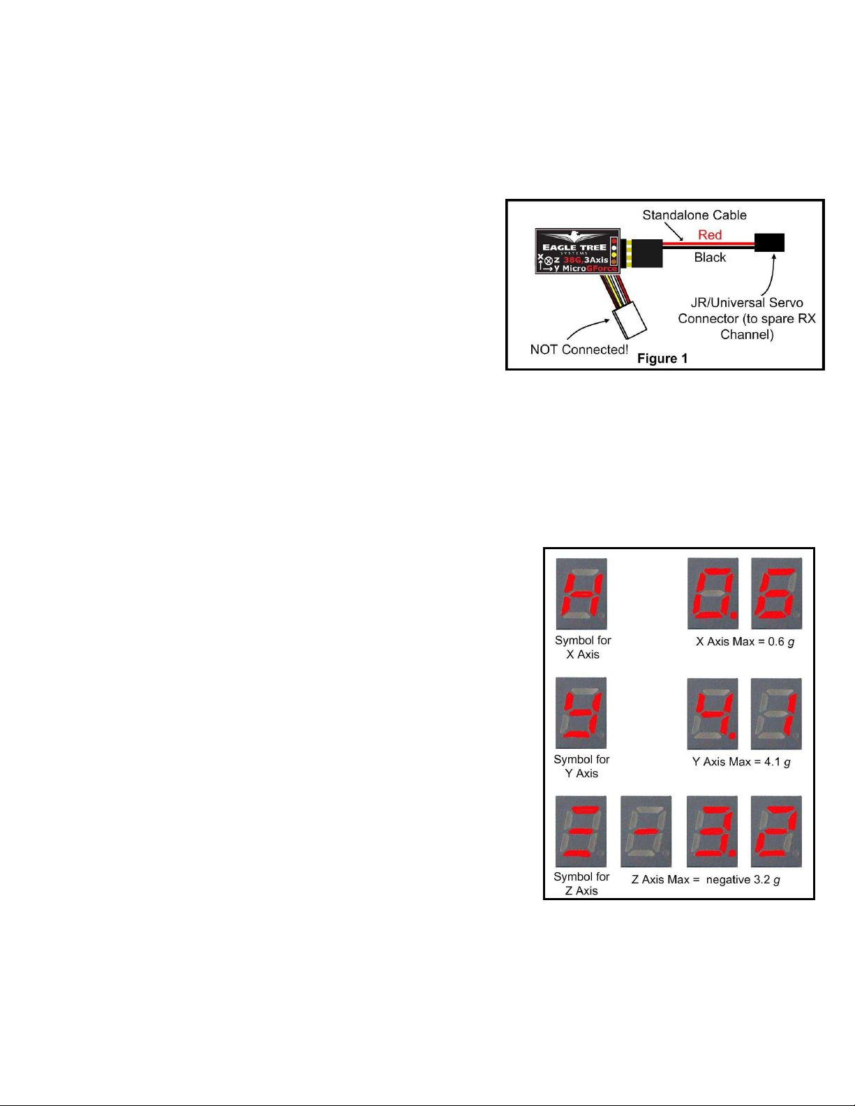
Display of the Maximum Values Encountered
After power up, the G-Sensor repeatedly displays the maximum values that were last
captured, cycling through the X, Y and Z axes. When displaying the values, the LED
first displays the axis symbol, then the G-Force reading for that axis. It does this
sequentially for each axis in the order of X, Y and Z.
The value itself for each axis is displayed with the sign first (if negative), then the most
significant digit, followed by each successive digit down to the first decimal place.
In the example at right, the maximum values detected during the session were: X = 0.6 g,
Y = 4.1 g,and Z= - 3.2 g.
Note that the “absolute value” of readings is used to compute the maximum. For
example, a value of -2 g sensed by the G-Sensor is greater than a value of +1.5 g, and
hence -2 will be displayed for that axis.
During a session, once the trigger G-Force is encountered on any axis, the sensor then
records all the values at that moment as the maximum values. Then, during the rest of
the session, any value for a particular axis that is greater than the presently recorded
value for that axis, replaces the prior recorded value. So, at the end of the session, the
maximum values encountered in each axis are displayed.
Rearming the Trigger G-Force
When the G-Sensor is disconnected from power and reconnected, the values stored from the last session are still displayed. But, the power
cycle rearms the trigger G-Force. When this trigger G-Force is encountered in your next session, the values from your last session are
overwritten with the new maximum values, even if the new maximum values are less than the maximum values you encountered in your last
session.
Changing the Trigger G-Force
By default, the trigger G-Force is set as 2 g. The other available values are 3, 4, and 5 g.
Copyright © 2011 Eagle Tree Systems, LLC
http://www.eagletreesystems.com
Page 3

Page
3
Note that the force of gravity is 1 g. So, when configured for 2 g, the MicroSensor will easily be triggered by normal handling. For
example, lifting it at a rate that causes an additional 1 g of acceleration on the Z axis will trigger the sensor. Along these lines, it is important
to handle the sensor with care when reading the last session’s maximum values or
they could be lost and replaced.
To change the G-Force trigger value, connect the Standalone Cable as described
above, but don’t power the G-Sensor. Then, connect a small piece of wire between
the unconnected pins of the Standalone Cable’s 4 pin connector, corresponding to the
brown and yellow dots on the label, as shown in Figure 2. This creates a jumper
between the brown and yellow labeled pins.
Then, power the G-Sensor via the Standalone Cable. Upon power up, the LED will display the previous G-Force trigger value, and then
flash the new value five times before beginning to display the last session’s max G-Force values. Each time the power is applied with the
jumper connected, the trigger value will increase by one, until reaching 5 g, at which time the trigger G-Force will return to 2 g. To change
the trigger value, just repeatedly disconnect and reconnect power, until the desired trigger value is flashed 5 times.
Using the G-Sensor with your eLogger V4 or V3
Windows Software and Firmware Update
To use the G-Sensor with your eLogger, you must update your software to Eagle Tree Windows Software version 9.45 or later. To
update, download the latest software from the support page of our website, located at http://eagletreesystems.com/Support/apps.htm . After
downloading and installing the software, if you have not already done so, set up the Recorder software as described in your eLogger
instruction manual. Then the firmware of your eLogger will need to be updated. To upgrade your firmware, just click “Hardware,
Firmware Control” and click the Update button for the eLogger.
Connecting the G-Sensor to the eLogger V4/V3
The G-Sensor plugs into the “LCD/OSD” or “LCD/TX” port of your eLogger V4 or V3, as shown in Figure 3. If you have a PowerPanel
or other MicroSensors, those can “daisy chain” connect to the pins on the side of your G-Sensor, with the polarity as indicated on the GSensor label. NOTE: The Standalone Cable must not be used when the G-Sensor is connected to the eLogger!
Configuring the G-Sensor with the Windows Software
Choose one or more of the G-Sensor options below:
Logging G-Force
To log G-Force, just click “Hardware -> Choose Parameters to
Log in the Recorder” and check the “3 Axis G-Force X, Y and
Z” box.
Displaying G-Force in the Windows Software
To display the G-Sensor Gauge and/or Numeric G-Force
readings, click “Software, Choose Instruments to Display on the PC Screen” and check one or more of the following:
* G-Force X Axis Meter, G-Force Y Axis Meter, and/or G-Force Z Axis Meter
* G-Force X Axis Numeric, G-Force Y Axis Numeric, and/or G-Force Z Axis Numeric
Then, after downloading data from your eLogger and clicking the “Play” button in the software, or running the eLogger in USB Live Mode,
the gauges and/or numeric displays will show the values corresponding to the G-Sensor readings.
Graphing G-Force
To graph G-Force, after downloading data from your eLogger, click “Data/2D Chart” and select G-Force X, G-Force Y and/or G-Force Z
for graphing. Also note that live G-Sensor readings can be displayed on the graph, by clicking the “Live Mode” button on the chart.
Displaying G-Force on the PowerPanel LCD
Select “Hardware, Configure PowerPanel Display”, and choose G-Force X Axis, G-Force Y Axis, G-Force Z Axis for PowerPanel
display.
Using the MicroSensor with your own Firmware/Microcontroller
Please see this document for information on using the MicroSensor with your own firmware:
http://www.eagletreesystems.com/support/manuals/microsensor-i2c.pdf
Copyright © 2011 Eagle Tree Systems, LLC
http://www.eagletreesystems.com
Page 4

Page
4
Troubleshooting
Below is a list of problems that may be encountered, and steps to remedy them. If your particular issue is not addressed by the below, visit
the Eagle Tree G-Sensor support thread at http://www.rcgroups.com/forums/showthread.php?t=1454098. Chances are someone has posted a
solution to your problem already. If not, posting your problem there will get a very quick response from the Eagle Tree community. If you
prefer to not post on the forum, or you feel there is a problem with your Eagle Tree hardware, please open a support ticket with us at
http://ticket.eagletreesystems.com
Issue: G-Force doesn’t vary in my recordings
Solutions:
• Ensure that the G-Sensor is connected correctly to the eLogger
• Ensure that you are logging G-Force, under “Hardware, Choose Parameters to Log in the Recorder”
Specifications (Approx)
• Acceleration recording limits:
o GFORCE-LOWG: to at least +/- 7 g (up to 8 g) in each axis.
o GFORCE-HIGHG: to at least +/- 38 g (up to 40 g) in the X and Y axis, and at least +/- 7 g (and up to 8 g) in the Z axis.
•
Resolution: approx. 0.05 G in each axis
•
Power input (Standalone Mode) : 4V to 16V (4V to 6V with the High G Sensor)
•
Weight: approximately 4 grams (0.15 oz)
•
Dimensions: approximately 28 mm x 16 mm x 10 mm (1.1” x 0.62” x 0.4”)
•
Precalibrated – no user calibration required
Limited Warranty
Eagle Tree Systems, LLC, warrants the G-Sensor to be free from defects in materials and workmanship for a period of one (1)
year from the date of original purchase. This warranty is nontransferable. If your unit requires warranty service during this
period, we will replace or repair it at our option. Shipping cost to us is your responsibility. To obtain warranty service, email
support@eagletreesystems.com for further instructions.
This limited warranty does not cover:
• The Software. See the Software license agreement for more information on Software restrictions.
• Problems that result from:
o
External causes such as accident, abuse, misuse, or problems with electrical power
o
Servicing not authorized by us
o
Usage that is not in accordance with product instructions
o
Failure to follow the product instructions
THIS WARRANTY GIVES YOU SPECIFIC LEGAL RIGHTS, AND YOU MAY ALSO HAVE OTHER RIGHTS WHICH
VARY FROM STATE TO STATE (OR JURISDICTION TO JURISDICTION). OUR RESPONSIBILITY FOR
MALFUNCITONS AND DEFECTS IN HARDWARE IS LIMITED TO REPAIR AND REPLACEMENT AS SET FORTH IN
THIS WARRANTY STATEMENT. ALL EXPRESS AND IMPLIED WARRANTIES FOR THE PRODUCT, INCLUDING,
BUT NOT LIMITED TO, ANY IMPLIED WARRANTIES AND CONDITIONS OF MERCHANTABILITY AND FITNESS
FOR A PARTICULAR PURPOSE, ARE LIMITED IN TIME TO THE TERM OF THE LIMITED WARRANTY PERIOD AS
DESCRIBED ABOVE. NO WARRANTIES, WHETHER EXPRESS OR IMPLIED, WILL APPLY AFTER THE LIMITED
WARRANTY PERIOD HAS EXPIRED. SOME STATES DO NOT ALLOW LIMITATIONS ON HOW LONG AN IMPLIED
WARRANTY LASTS, SO THIS LIMITATION MAY NOT APPLY TO YOU.
WE DO NOT ACCEPT LIABILITY BEYOND THE REMEDIES PROVIDED FOR IN THIS LIMITED WARRANTY OR
FOR CONSEQUENTIAL OR INCIDENTAL DAMAGES, INCLUDING, WITHOUT LIMITATION, ANY LIABILTY FOR
THIRD-PARTY CLAIMS AGAINST YOU FOR DAMAGES, FOR PRODUCTS NOT BEING AVAILABLE FOR USE, OR
FOR LOST DATA OR LOST SOFTWARE. OUR LIABILITY WILL BE NO MORE THAN THE AMOUNT YOU PAID
FOR THE PRODUCT THAT IS THE SUBJECT OF A CLAIM. THIS IS THE MAXIMUM AMOUNT FOR WHICH WE
ARE RESPONSIBLE. SOME STATES DO NOT ALLOW THE EXCLUSION OR LIMITATION OF INCIDENTAL OR
CONSEQUENTIAL DAMAGES, SO THE ABOVE LIMITATION OR EXCLUSION MAY NOT APPLY TO YOU.
Copyright © 2011 Eagle Tree Systems, LLC
http://www.eagletreesystems.com
 Loading...