

Page 1

Instruction Manual for the Seagull Jet ECU Interfaces
Document Version 1.2
Model #’s ECU-JETCAT, ECU-AMT, ECU-FADEC
Thank you for your purchase! This instruction manual will guide you through the installation and operation of your Seagull
Jet ECU Interface. Please read the entire manual carefully before proceeding. If, after you read the manual (including the
Troubleshooting section!!), you have further questions or problems, see the Support page on
http://www.eagletreesystems.com
Features and Benefits of the Jet ECU Interface
The Jet ECU Interface, in conjunction with our Seagull Pro Flight System, provides real-time data and audible feedback
about the state of your Model Jet, while you are flying! Think of the Jet ECU Interface as a Wireless Engine Data
Terminal/GSU for your Jet.
Data such as ECU Turbine RPM, Turbine temperature, Throttle %, ECU Pack and Pump Voltage, and ECU status
messages are retrieved from your ECU and transmitted wirelessly to the Seagull Dashboard. Audible alarms can be
programmed for low Turbine RPM and temperature for early flameout alert, and for ECU pack voltage for low battery
indication. All these parameters are in addition to the standard data parameters that are available on the Pro System.
In addition to display on the LCD screen of the Wireless Dashboard, if the Dashboard is connected to a laptop via USB,
all the ECU data are available live with the Windows Virtual Cockpit application!
Packing List
Your package should include the following: Jet ECU Interface Cable (either AMT Netherlands, JetCat or FADEC), and a
printed version of this manual. Please check your box for printed addenda to this manual which may be included if
changes were made after printing.
Requirements
The Jet ECU Interface requires a Seagull Pro Flight System, with Windows application version 3.39 or later. The latest
version is available on the support page of our website. The Recorder and Dashboard firmware needs to be updated using
“Tools, Firmware Control.”
For JetCat users, version 4.00g of the JetCat ECU is required. For AMT Netherlands users, the Recorder must be
powered with a 4 cell (4.8v pack).
Do you have an ECU that is not currently supported? If so, email us at info@eagletreesystems.com
to help!
How the Jet ECU Interface Works
The Jet ECU Interface cable plugs between the Pro Flight Recorder the data/telemetry port of your ECU. After simple
Windows configuration, the Recorder reads the ECU parameter data and transmits it to the Wireless Dashboard.
for additional information, or email us at support@eagletreesystems.com.
and we may be able
Copyright © 2005 Eagle Tree Systems, LLC
http://www.eagletreesystems.com
Page 2
Page 2
Installing and Powering the Recorder in Your Jet
First, read the Seagull Pro Flight System user manual for overall Seagull installation information.
The Recorder can be powered from your Jet’s receiver battery pack, via the included Y cables, or from its own battery,
plugged into one of the Pro system’s servo connectors.
The AMT Netherlands ECU Interface REQUIRES a 4.8v battery pack. The other ECU Interfaces should operate
correctly on either a 4.8v or 6v pack. See the Seagull Pro Flight System user manual for more information on powering
the recorder.
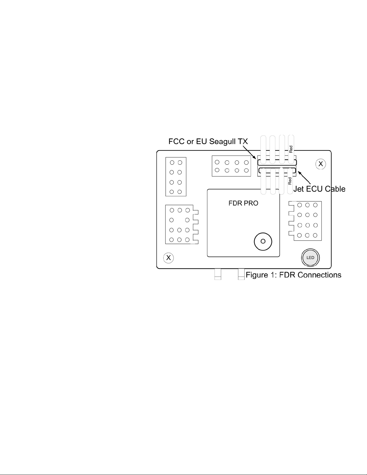
Connecting the Jet ECU Cable
The Jet ECU Interface cable connects to the “GPS/EU Tx” port on the Pro Recorder, with the Brown wire to the left, as
shown in Figure 1.
NOTE: If you have the EU TX, you must
connect the TX to the “FCC” port, as shown in
the figure. Before doing so, the recorder must
be configured for this mode. Please see your
Seagull Pro Flight System manual for
information on how to do this, under the
“Connecting the Seagull Transmitter to your
Data Recorder” under the “Using GPS”
subsection.
The other end of the cable plugs into your ECU
as follows:
JetCat: the cable plugs into the Data Bus port
of your ECU, or into the Data Bus port of your
ECU sensor board. Additionally, the cable can
be plugged into the second port of your GSU, if
you desire to see both GSU and Seagull
information about the ECU on the ground.
AMT Netherlands: the cable plugs into the 3 pin Telemetry wire of the ECU. If desired, a standard servo Y cable
(NOT the custom Y cables included with the Recorder) can be used to ‘Y” the Data Terminal and the Seagull
simultaneously.
FADEC: The cable plugs into the data port of the ECU. It might be possible to build a Y cable to allow simultaneous
Data Terminal and Seagull operation, but we have not tested this.
Note: it is fine to hot plug and unplug the Seagull ECU cable to/from the ECU, as desired.
Configuring the Jet ECU Interface with the System
Configuration of the Seagull Pro system with the ECU Interface is straightforward.
First, make sure you have installed our latest application from the website, and updated the firmware on the Recorder and
Dashboard, as described above in the Requirements section.
Once this is complete, run the application, connect the Recorder to USB, and choose “Tools, Jet ECU Setup.” Select the
type of ECU you have, and click “OK.”. The application will then prompt you to attach the Dashboard to USB, and the
“Seagull Dashboard Data Setup Utility” application page should appear, as shown below:
Copyright © 2005 Eagle Tree Systems, LLC
http://www.eagletreesystems.com
Page 3

Now, you should see the list of ECU
parameters that can be displayed on the
Dashboard, as well as the other Seagull
Parameters. Select the desired
parameters and configure alarms on the
new ECU parameters as described in your
Seagull Pro Flight System manual.
Here is specific information about the
ECU parameters:
ECU Throttle % - this indicates the
throttle deflection percentage
ECU Turbine Temperature – this
indicates the turbine temperature. Note
that it is ALWAYS in Degrees C on the
Dashboard, even if English units are
selected in the application
ECU Turbine RPM – this indicates the
turbine RPM. IMPORTANT: please
make sure that you place the RPM display
on either the left upper or left lower
display location (not on the right side of
the screen). This is because RPM can go
about 99,999, which means it won’t
display properly on the right side.
ECU Status – this page on the Dashboard
indicates the status of the ECU. The messages vary depending on which ECU you have, and should be similar to the
messages your Data Terminal/GSU currently displays. When no ECU is detected, “ECU NOT DETECTED” is displayed
on the ECU status page of the dashboard.
ECU Pack Voltage – this indicates the voltage of the ECU’s main power supply.
ECU Pump Voltage – this indicates the current pump voltage. NOTE: on the FADEC, this indicates the pump duty
cycle.
Page 3
Live Mode Application Display
All of the ECU parameters can be displayed in application Live Mode, when either the Dashboard or the Recorder is
connected to your PC/Laptop via USB. To configure the parameters to display in Live Mode, click “Tools, Choose
Instruments to Display on PC Screen” and the ECU options should appear on the righthand side of this page.
Range Checking and Flying
IMPORTANT: It is unlikely that the installation of the Eagle Tree system will cause problems with radio range. But, as
always, it is critical to do an antenna-down range check, per your jet/radio manufacturer’s instructions, after making any
changes to your jet’s electronics (and frankly before every flight session). Eagle Tree recommends that the range check
be done with the turbine running, to completely verify operation (if this can be done safely).
Happy Flying! We’d love to see pictures of your installation and get your feedback. Just email us at
info@eagletreesystems.com.
Troubleshooting
Below is a list of problems that may be encountered, and steps to remedy them. If your particular issue is not addressed
by the below, see the Support page on http://eagletreesystems.com
Copyright © 2005 Eagle Tree Systems, LLC
http://www.eagletreesystems.com
or email us at support@eagletreesystems.com.
Page 4

Include a full description of your problem, your machine configuration, brand/model/version of ECU, application version,
Dashboard and Recorder firmware version and any other relevant details.
Issue: “ECU NOT DETECTED” appears on the ECU Status page of the LCD Dashboard, after configuration
Solution:
• Make sure you have downloaded the latest Windows application and installed the latest firmware, as described in
the Requirements section above.
• Make sure you have followed the application configuration instructions above.
• Make sure that you have connected the ECU Interface cable appropriately, as described above.
• Plug in your Engine Data Terminal/GSU, if you have one, and verify that it is reading correctly.
Issue: I have reduced antenna-down range with the ECU Interface installed
Solution:
• Try isolating the problem – disconnect the ECU Interface cable, and see if the range improves. If it does not
improve, please see the Troubleshooting section in the Seagull Pro Flight System user manual. If range does
change when disconnecting the ECU Interface cable, please contact Eagle Tree Systems immediately.
Page 4
Limited Warranty
Eagle Tree Systems, LLC, warrants the Jet ECU Interface Cable to be free from defects in materials and workmanship for
a period of one (1) year from the date of original purchase. This warranty is nontransferable. If your unit requires
warranty service during this period, we will replace or repair it at our option. Shipping cost to us is your responsibility.
To obtain warranty service, email us to request an RMA number. No returns will be accepted without this number.
This limited warranty does not cover:
• The Software included with the System. See the Software license agreement for more information on Software
restrictions.
• Problems that result from:
o External causes such as accident, abuse, misuse, or problems with electrical power
o Servicing not authorized by us
o Usage that is not in accordance with product instructions
o Failure to follow the product instructions
THIS WARRANTY GIVES YOU SPECIFIC LEGAL RIGHTS, AND YOU MAY ALSO HAVE OTHER RIGHTS
WHICH VARY FROM STATE TO STATE (OR JURISDICTION TO JURISDICTION). OUR RESPONSIBILITY FOR
MALFUNCITONS AND DEFECTS IN HARDWARE IS LIMITED TO REPAIR AND REPLACEMENT AS SET
FORTH IN THIS WARRANTY STATEMENT. ALL EXPRESS AND IMPLIED WARRANTIES FOR THE
PRODUCT, INCLUDING, BUT NOT LIMITED TO, ANY IMPLIED WARRANTIES AND CONDITIONS OF
MERCHANTABILITY AND FITNESS FOR A PARTICULAR PURPOSE, ARE LIMITED IN TIME TO THE TERM
OF THE LIMITED WARRANTY PERIOD AS DESCRIBED ABOVE. NO WARRANTIES, WHETHER EXPRESS OR
IMPLIED, WILL APPLY AFTER THE LIMITED WARRANTY PERIOD HAS EXPIRED. SOME STATES DO NOT
ALLOW LIMITATIONS ON HOW LONG AN IMPLIED WARRANTY LASTS, SO THIS LIMITATION MAY NOT
APPLY TO YOU.
WE DO NOT ACCEPT LIABILITY BEYOND THE REMEDIES PROVIDED FOR IN THIS LIMITED WARRANTY
OR FOR CONSEQUENTIAL OR INCIDENTAL DAMAGES, INCLUDING, WITHOUT LIMITATION, ANY
LIABILTY FOR THIRD-PARTY CLAIMS AGAINST YOU FOR DAMAGES, FOR PRODUCTS NOT BEING
AVAILABLE FOR USE, OR FOR LOST DATA OR LOST SOFTWARE. OUR LIABILITY WILL BE NO MORE
THAN THE AMOUNT YOU PAID FOR THE PRODUCT THAT IS THE SUBJECT OF A CLAIM. THIS IS THE
MAXIMUM AMOUNT FOR WHICH WE ARE RESPONSIBLE.
SOME STATES DO NOT ALLOW THE EXCLUSION OR LIMITATION OF INCIDENTAL OR CONSEQUENTIAL
DAMAGES, SO THE ABOVE LIMITATION OR EXCLUSION MAY NOT APPLY TO YOU.
Copyright © 2005 Eagle Tree Systems, LLC
http://www.eagletreesystems.com
 Loading...