

Eagle Tech PCI30G, PCI30GA32, PCI30G32, PCI30GA, PCI30F User Manual

PCI30FG Series
PCI PnP Analog Input Board
User’s Manual
PCI30G, PCI30GA, PCI30G32, PCI30GA32
PCI30F, PCI30FA, PCI30F32, PCI30FA32
Eagle Technology – Cape Town, South Africa
Copyright © 1999-2002
www.eagledaq.com

PCI30FG User Manual
Analog Input Boards
Data Acquisition and Process Control
© Eagle Technology
31-35 Hout Street • Cape Town • South Africa
Phone +27 21 423 4943 • Fax +27 21 424 4637
Email eagle@eagle.co.za
Eagle Technology © Copyright 2002 i

PCI30FG User Manual
Copyright
All rights reserved. No part of this publication may be reproduced, stored in a
retrieval system, or transmitted, in any form or any means, electronic,
mechanical, by photographing, recording, or otherwise without prior written
permission.
Copyright © Eagle Technology, South Africa
August 2002
Revision 1.2
Information furnished in this manual is believed to be accurate and reliable;
however no responsibility is assumed for its use, or any infringements of
patents or other rights of third parties, which may result from its use.
Trademarks and Logos in this manual are the property of their respective
owners.
Product Warranty
Eagle Technology, South Africa, warrants its products from defect in material
and workmanship from confirmed date of purchase for a period of one year if
the conditions listed below are met. The product warranty will call the Eagle
Technology Data Acquisition Device short as ETDAQD.
• The warranty does not apply to an ETDAQD that has been previously
repaired, altered, extended by any other company or individual outside the
premises of Eagle Technology.
• That a qualified person configure and install the ETDAQD, and damages
caused to a device during installation shall make the warranty void and
null.
• The warranty will not apply to conditions where the ETDAQD has been
operated in a manner exceeding its specifications.
Eagle Technology, South Africa, does not take responsibility or liability of
consequential damages, project delays, damaging of equipment or capital
loss as a result of its products.
Eagle Technology, South Africa, holds the option and final decision to repair
or replace any ETDAQD. Proof of purchase must be supplied when
requesting a repair.
Eagle Technology © Copyright 2002 ii

PCI30FG User Manual
TABLE OF CONTENTS
1 INTRODUCTION 1
Features 1
Applications 1
Key Specifications 2
Software Support 2
2 INSTALLATION 3
Package 3
Hardware Installation 3
Software Installation 4
Windows 98 4
Post installation 7
Windows NT/2000 8
Configuration 9
Accessories 9
3 INTERCONNECTIONS 10
External Connectors 10
Pin Assignments 10
Signal Definitions 12
Analog Input 12
Single Ended Inputs 12
Differential Inputs 13
Analog Output 14
Digital Input/Output 14
Counter-Timer 14
4 PROGRAMMING GUIDE 15
EDR Enhanced API 15
Eagle Technology © Copyright 2002 iii

PCI30FG User Manual
Digital Inputs/Outputs 16
Reading the Digital Inputs 16
Writing to the Digital Outputs 16
Counters 17
Writing the initial counter value 17
Reading a counter 17
Configuring a counter 18
Analog Output 19
Writing to a DAC channel 19
Analog Input 20
Reading a single voltage from a channel 20
Configuring the ADC subsystem for scanning 20
Starting and Stopping the ADC process 22
Getting data from the driver buffer 23
Querying the ADC subsystem 23
5 CALIBRATION 25
Requirements 25
Software 25
Connection 26
Variable Resistor Description 26
A/D Calibrating Procedure 27
Calibrating the PCI30Gx series 27
A. SPECIFICATION 28
B. CONFIGURATION CONSTANTS 29
Query Codes 29
Error Codes 30
Digital I/O Codes 30
C. LAYOUT DIAGRAM 31
D. ORDERING INFORMATION 32
Eagle Technology © Copyright 2002 iv

PCI30FG User Manual
Table of Figures
Figure 2-1 Add New Hardware Wizard Step1 ..................................................4
Figure 2-2 Add New Hardware Wizard Step2 ..................................................5
Figure 2-3 Add New Hardware Wizard Step3 ..................................................5
Figure 2-4 Add New Hardware Wizard Step4 ..................................................6
Figure 2-5 Add New Hardware Wizard Step5 ..................................................6
Figure 2-6 Restart Your Computer...................................................................7
Figure 2-7 System Properties...........................................................................7
Figure 2-8 EagleDAQ.......................................................................................8
Figure 2-9 A/D Span Jumper............................................................................9
Figure 3-1 Single ended analog input ............................................................13
Figure 3-2 Differential Analog Inputs..............................................................13
Figure 4-A EDR Enhanced Design.................................................................15
Figure 6-1 A/D Calibration Connections.........................................................26
Eagle Technology © Copyright 2002 v

PCI30FG User Manual
Table of Tables
Table 3-1 External Analog Connector - SCSI-II-50F CENT............................11
Table 3-2 Internal DIO/CT Connector – IDC-40M ..........................................11
Table 3-3 External DIO/CT Connector - DB-37M ...........................................11
Table 3-4 Signal definitions............................................................................12
Table 4-1 Counter Assignment.......................................................................17
Table 4-2 Counter Configuration ....................................................................18
Table 6-1 VR Assignment ..............................................................................26
Table D-1 Ordering Information......................................................................32
Eagle Technology © Copyright 2002 vi

PCI30FG User Manual
1 Introduction
The PCI30FG series are 32-bit bit PCI bus architecture data acquisition
boards. They are available in two basic models, the G and F series. They can
samples at 100kHz or 330kHz respectively. Addition to analog input, they also
have analog output, digital input/output and counter-timer capabilities. For this
reason the PCI30FG is an excellent all purpose data acquisition device with
extensive analog input capabilities.
Features
The PCI30FG does have some very unique features and are short listed
below:
• 32-bit PCI bus Revision 2.1 compliant
• 8/16 differential or 16/32 single-ended A/D inputs
• 2K word A/D FIFO
• Auto channel scanning
• Software controlled input ranges and gains
• 3 x 8-bit I/O ports
• 4 x 16-bit user counter-timers
Applications
The PCI30FG can be used in the following applications:
• Voltage monitoring
• Voltage control
• FFT signal calculation
• General process control
• Frequency measurement
• Pulse counting
Eagle Technology © Copyright 2002 1

PCI30FG User Manual
Key Specifications
• A/D resolution: 12-bits
• D/A resolution: 12-bits
• DIO width: 8-bits
• CT width: 16-bits
• A/D non-linearity: less than ±0.75LSB
• A/D ranges: ±5V, ±10V, 0-10V
• A/D scan rate: 100kHz or 330kHz
• A/D, D/A interfaces via a 50 way SCSI right angle female centronics
connector
• Digital I/O, Counter-timer via IDC40 Header
Software Support
The PCI30FG is supported by EDR Enhanced and comes with an extensive
range of examples. The software will help you to get your hardware going very
quickly. It also makes it easy to develop complicated control applications
quickly. All operating system drivers, utility and test software are supplied on a
CD-Rom.
Eagle Technology © Copyright 2002 2
PCI30FG User Manual
2 Installation
This chapter describes how to install and configure the PCI30FG for the first
time. Minimal configuration is necessary; almost all settings are done through
software. The PCI BIOS will assign an I/O base address and interrupt level.
Package
PCI30FG package will contain the following:
• PCI30FG PCI board
• EDR Enhanced Software Development Kit CD-Rom
Hardware Installation
This section will describe how to install your PCI30FG into your computer.
• Switch off the computer and disconnect from power socket.
Failure to disconnect all power cables
can result in hazardous conditions, as
there may be dangerous voltage levels
present in externally connected
• Remove the cover of the PC.
• Choose any open PCI slot and insert PCI30FG.
• Insert bracket screw and ensure that the board sits firmly in the PCI
socket.
• Install digital I/O connector cable.
• Replace the cover of the PC.
• Reconnect all power cables and switch the power on.
• The hardware installation is now completed.
cables.
Eagle Technology © Copyright 2002 3

PCI30FG User Manual
Software Installation
Windows 98
Installing the Windows 98 device driver is a very straightforward task.
Because it is plug and play Windows will detect the PCI30FG as soon as it is
installed. No setup is necessary. You simply only have to supply Windows
with a device driver.
Wait until Windows detects the new hardware
Figure 2-1 Add New Hardware Wizard Step1
Select Next
Eagle Technology © Copyright 2002 4
PCI30FG User Manual
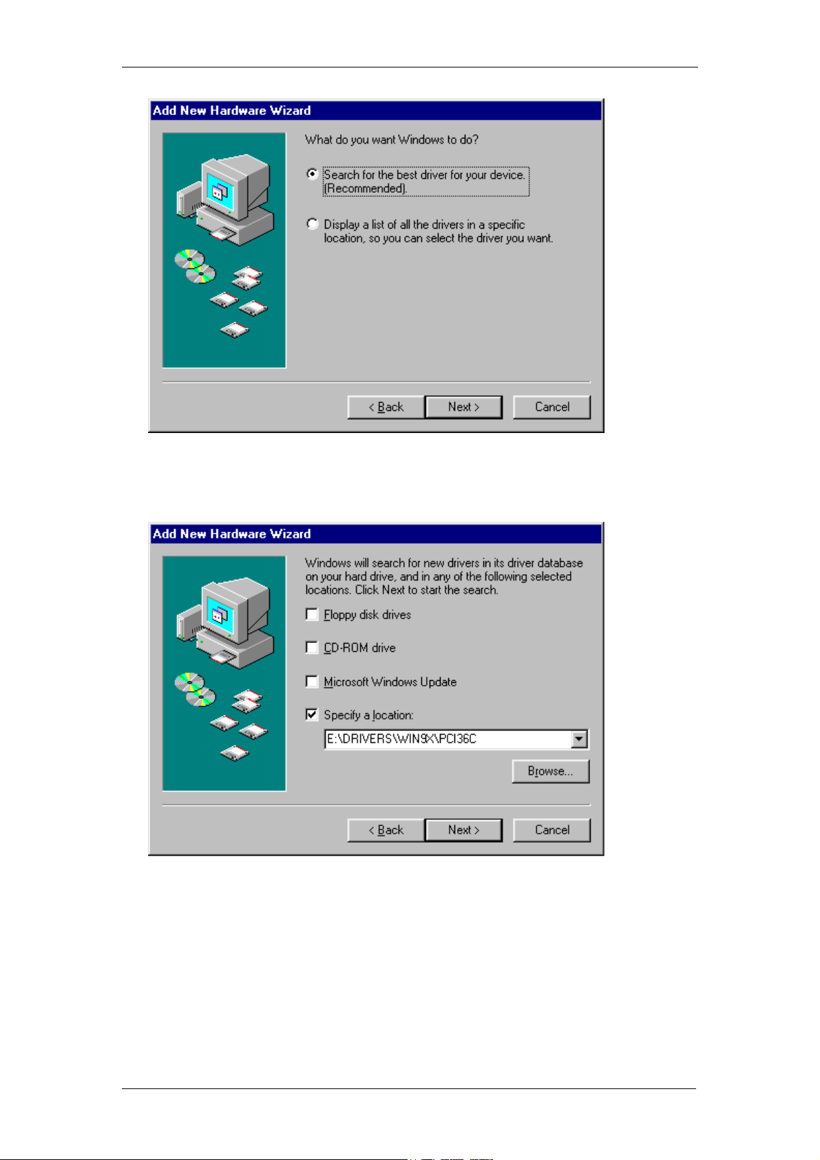
Figure 2-2 Add New Hardware Wizard Step2
Select default option, search for best driver and select next
Figure 2-3 Add New Hardware Wizard Step3
Select specify a location and enter the directory location of the driver
on your EDR Enhanced SDK CD Rom
<CDROM>\EDRE\DRIVERS\WDM\PCI30FG
Select Next to proceed
Eagle Technology © Copyright 2002 5
 Loading...