

TECHNICAL MANUAL
200852
Count Advanced
3 PRESET COUNTER
with BATCHING
and TOTALIZER
MAX count Advanced is a Powerful three preset
counter with a presettable Batch Counter and a
Background Totalizer. MAX features guided
programming using English prompts for easy setup
and operation. MAX is clearly the best choice for
industrial counting applications.
FEATURES
• Simultaneous Counter , T otalizer , and
Batching
• “ON THE FL Y” Preset Programming
• A-B, A+B and Quadrature operation
• Three Preset, Six Decade Main Counter
• Six Decade Start count Preset
• Six Decade Single Preset Batch Counter
• Six Decade Background T ot alizer
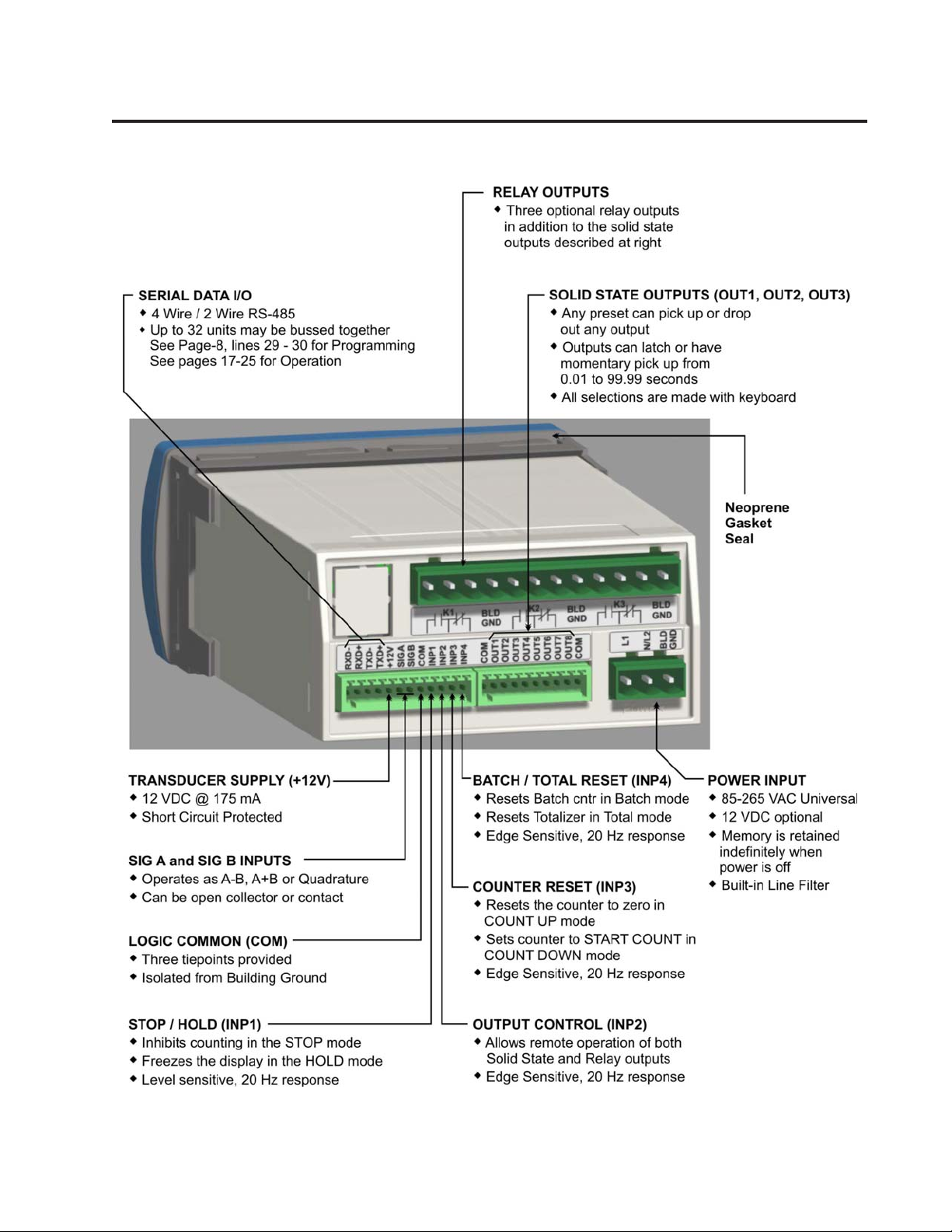
• 4 Wire / 2 Wire RS-485 Provides LOCAL
and REMOTE process Control Capability
Modbus RTU protocol
• COUNTER RESET , STOP / HOLD input s
• BA TCH / TOTAL RESET input
• OUTPUT CONTROL input
• Non-Volatile Memory (FRAM) for Counters
& Programmed parameters
• Built In Self- Diagnostics
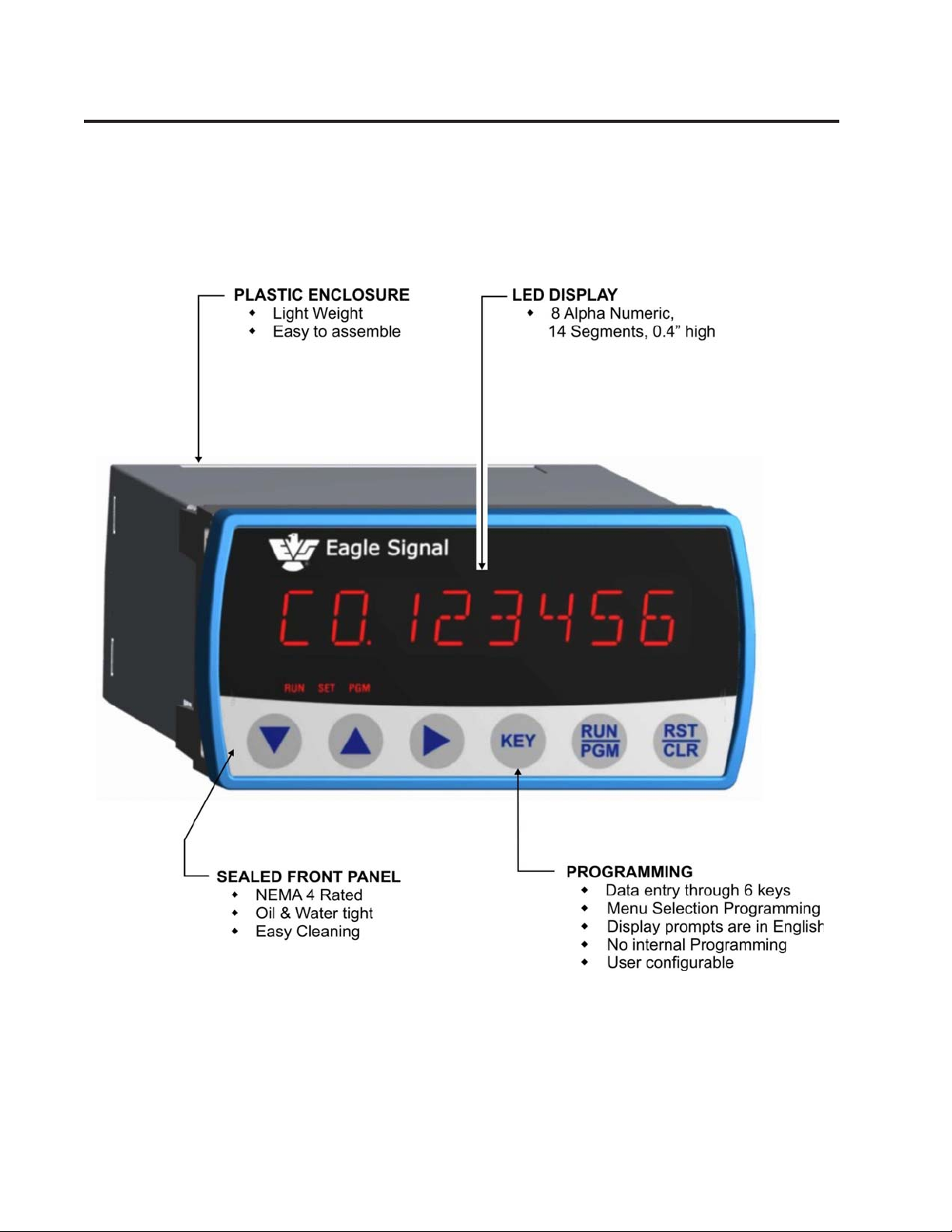
• Eight Alpha Numeric,14 Segments LED
display
KEY SPECIFICATIONS
• DC to 40kHz Operation
• Programmable Input Logic (x1,x2, or x4)
• Five Decade Calibrator
• Three Relay and Three Transistor Outputs
• 10Amp Relay Contact Rating
• Programmable Relay Hold Time xx.xx sec
• +12VDC @ 175mA Transducer Supply
• 85-265 V AC Operation (12VDC Optional)
INDEX TO CONTENTS
Overview p. 2,3
Specification p. 4
Front Panel Controls p. 5
Programming p. 6 - 11
Applications p. 12 - 13
Installation p. 14 - 16
Serial Communication Overview p. 17
Serial Interface Protocol p. 18 - 25
Ordering Information p. 26
OVERVIEW ...
Page 2
OVERVIEW ...
Page 3

SPECIFICATIONS ...
Page 4
Input Power: 85-265 VAC, 50-60Hz, 20 VA
12 VDC @ 0.5 A. Optional
Accessory Supply: 12 VDC @ 175 mA.
Main Counter:
Range: 6 Decades
Presets: 3 Individual with 6 decade range
Operation: A-B, A+B, Quadrature
Reset Input: External and front panel
Count Rate: 40 kHz internal
(40kHz external input frequency
with x1 logic)
(20 kHz external input frequency
with x2 logic)
(10 kHz external input frequency
with x4 logic)
Calibrator:
Range: 5 Decade, 0.0001 to 9.9999
Operation: Calibrates Main Counter and
totalizer
Totalizer:
Range: 6 Decade
Operation: Totalizes calibrated input counts
Batch Counter:
Range: 6 Decade
Presets: 1 with 6 Decade range
Operation: Count UP by detecting Auto
Resets of main counter.
Output: Programmable assignment
Signal A and B Inputs:
Input Frequency: DC to 40kHz,
(40kHz external input frequency
with x1 logic)
(20 kHz external input frequency
with x2 logic)
(10 kHz external input frequency
with x4 logic)
Input Type: Single ended, Current Source
Input Logic: x1,x2,x4
Input High Level: 3.25 VDC min.
Input Low Level: 1.75 VDC max.
Input Impedance: 1.0 kΩ to common
Input current: 3.25mA. steady state
Input Response: 10µs. min high and low time
Control Inputs:
Input Frequency: DC to 20Hz Max. each input.
RESET input 100Hz response
Input Type: Single ended, current sinking
Input Logic: Both edge & Level sensitive as
defined by input use
Input High Level: 10VDC min. to 20 VDC max.
Input Low Level: 0 VDC min. to 2 VDC max.
Input Impedance: 4.7 kΩ pullup to +12 Vdc
Input Current: 2.5 mA. Steady state
Input Response: 25 ms. make and break time
Display:
Decades: Eight Alpha Numeric, 0.4" red LED
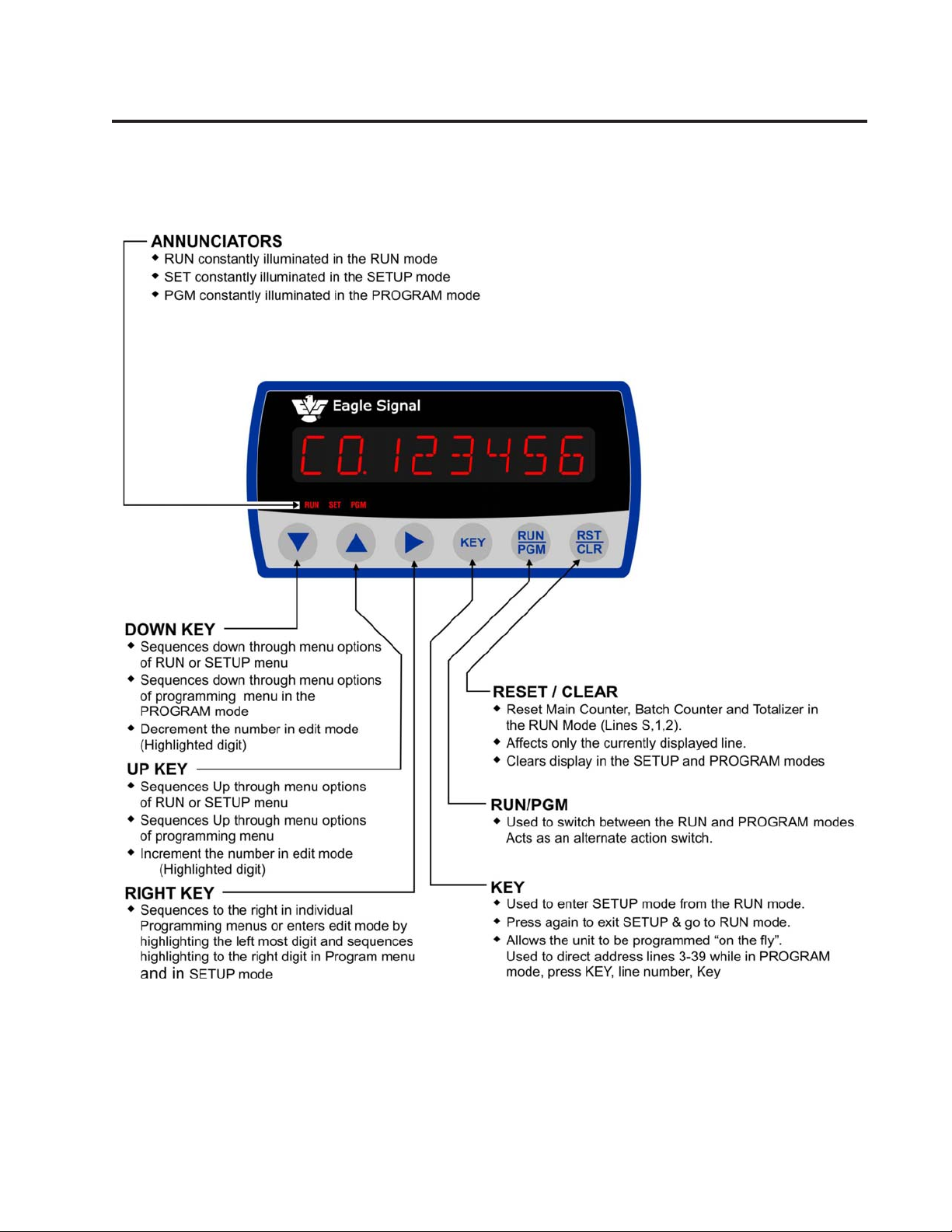
Annunciators: Three Annunciators RUN, SET, PGM
Decimal Point: User programmable
Range: x.xxxxx to xxxxxx
Keyboard: Sealed tactile feel, 6 positions
Program Security: Program LOCK for lines 3-39
Control Outputs:
Type: 3 Solid State,
100mA sink max., 24 VDC max.
Optional: 3 SPDT Relays, rated
10Amp 30VDC/270VAC Resistive
Serial Interface:
Type: RS-485 compatible (4 or 2
wire options with modbus support)
Baud Rate: Selectable; 1200, 2400, 4800 or 9600
Data: Binary
Format: 1 START Bit, 8 Bit data , 1 ST OP Bit
Protocol: ModBus RTU
I.D. Number: Programmable 1 to 32: Allows
multidrop systems.
Diagnostics:
Test 0: Keyboard Test
Test 1: FRAM Test
Test 2: Input Test
Test 3: Output Test
Test 4: Display Test
Test 5: Flash Memory Test
Test 6: Date Code Test
Test 7: Serial I/O Test
Test 8: Return to Factory Programming
Mechanical:
Enclosure Plastic Moulded
2.0” High x 4.0 Wide x 5.56”Deep
Cutout 1.77”[ 45mm] x 3.62” [92mm]
Panel Thickness 1/16” to 1/4”
Panel Depth 5.68” Minimum
Weight 0.68 lb [308 gm]
Environmental:
Operating Temp: -15°C to +65°C
Storage Temp: -30°C to +85°C
Ambient Humidity: 90% and noncondensing
Controller Error Codes
1. Low AC Line Voltage ( Displays LOW AC)
2. Input Frequency Too fast (Displays FREQ MAX)
Pess To clear Error Code
FRAM Error Codes
1. Run Mode parameters corrupted (FRUNFAIL).
2. Program Mode parameters corrupted (FPGMFAIL).
Note: Power cycle to clear the FRAM error
FRONT PANEL CONTROLS...
Page 5

PROGRAMMING ...
Page 6
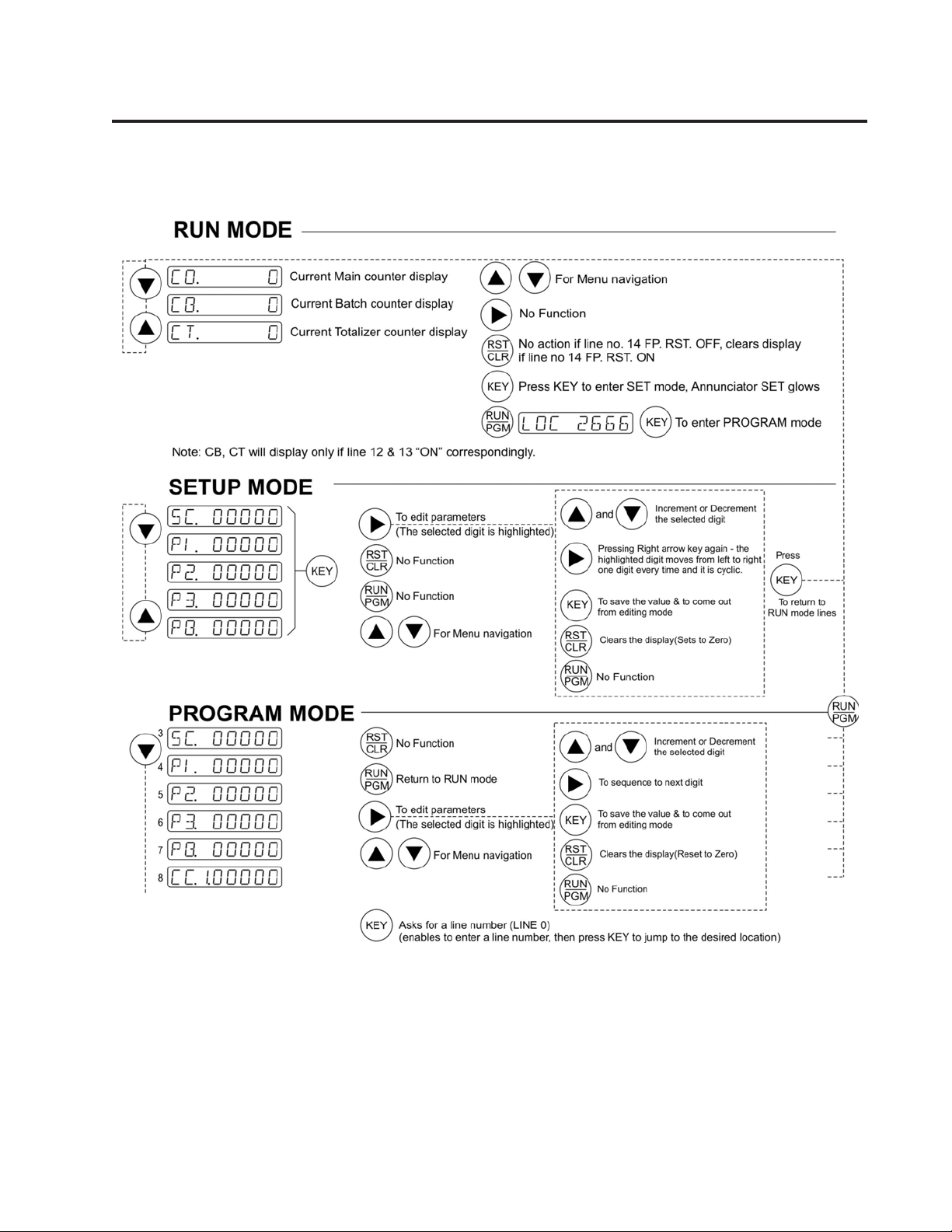
RUN MODE:
LINE FUNCTION DESCRIPTION
S COUNT VALUE Indicates current Count
1 BA TCH COUNT V ALUE Indicates current Batch Count. Conditional: Batch Counter (line 12)
must be ‘ON’.
2 TOT AL COUNT V ALUE Indicates current T ot alizer Count. Conditional: Totalizer (line 13)
must be ‘ON’).
SETUP MODE: SETUP MODE (inhibited by the PRESET LOCK being ‘ON’)
3 STAR T COUNT Numeric V alue for “set to a number”. Conditional: Direction (line 10)
must be ‘Down’.
4 PRESET 1 Numeric value for Preset 1. Conditional: P1 (line 23) must have
assignment.
5 PRESET 2 Numeric value for Preset 2. Conditional: P2 (line 24) must have
assignment.
6 PRESET 3 Numeric value for Preset 3. Conditional: P2 (line 25) must have
assignment.
7 BA TCH PRESET Numeric value for Batch Preset. Conditional: Batch Counter (line
12) must be ‘ON’ and Batch Preset (line 26) must have assignment.
PROGRAM MODE
3 STAR T COUNT Numeric value for “Set to a number” (for Count Down mode only).
4 PRESET 1 Numeric value of Preset 1.
5 PRESET 2 Numeric value of Preset 2.
6 PRESET 3 Numeric value of Preset 3.
7 BA TCH PRESET Numeric V alue for Batch Preset.
8 CORRECTION CONSTANT Numeric constant for inputs A & B. See p age-12.
PROGRAMMING ...
Page 7

PROGRAMMING ...
9 INPUT MODE Selects A-B, A+B X1 for open collector or contact inputs;
Selects A-B, A+B X2 or Quadrature X2, X4 for open collector inputs
10 COUNT DIRECTION Select “reset to zero” for UP or “set to number” for DOWN
11 DECIMAL POINT Decimal point position for Count, Total Count, and Presets.
12 BATCH COUNTER Select ON or OFF
13 TOTALIZER Select ON or OFF
14 FRONT PANEL RESET Select ON or OFF
15 PRESET LOCK Select ON or OFF. Affects entry into SETUP mode
16 COUNTER RETENTION Select ON or OFF (Saves count value during power outages).
17 RESET TYPE Select open collector or contact closure input types
18 STOP / HOLD MODE Select STOP count or Display HOLD function via external input.
19 BATCH / TOT AL RESET MODE Select BATCH reset or TOTALIZER reset functions via external input
20 OUTPUT 1 Select latched or pulsed operation for output 1
21 OUTPUT 2 Select latched or pulsed operation for output 2
Page 8
22 OUTPUT 3 Select latched or pulsed operation for output 3
23 P1 ASSIGNMENT Assign output operations to Preset 1
24 P2 ASSIGNMENT Assign output operations to Preset 2
25 P3 ASSIGNMENT Assign output operations to Preset 3
26 BA TCH PRESET ASGMNT Assign output operations to Batch Preset.
27 RESET INPUT ASGMNT Assign output operations to Reset Input
28 OUTPUT CONTROL ASGMNT Assign output operations to Output control input.
29 BAUD RA TE Selects OFF,1200, 2400, 4800 or 9600 baud.
30 ID NUMBER Serial ID Number. Programs unit serial ID. (01 - 32)

PROGRAMMING ...
Page 9

PROGRAMMING ...
The MAX Count Advanced controller provides a group of diagnostics to self test the controller and field wiring as
well as helps the user diagnose machinery malfunctions. Nine diagnostic tests are provided and may be run only
while the unit is in the PROGRAM mode. These tests should be done “offline” (user’s process not being controlled).
The tests are outlined below along with the keyboard commands to control them.
LINE DIAGNOSTIC DESCRIPTION
31 TEST 0 Keyboard Test: Display echoes on each key press.
32 TEST 1 FRAM Memory Test.
33 TEST 2 Input Tests: Test for “Closures” on Inputs.
34 TEST 3 Output Test: Press X key to select the Relays 1-3 using Sand T, press X Key to
turn ON. Press CLR to Turn ‘OFF’.
35 TEST 4 Display Test: Illuminates all segments.
36 TEST 5 Flash Memory test: Checksum comparison for program memory .
37 TEST 6 Version code Test: Displays date code version of firmware.
38 TEST 7 Serial Test: Provides loop-back test of the serial transmitter and receiver (will
indicate ‘FAIL’ if the loop back connectors are not made).
39 TEST 8 Returns controller to the factory programmed state.
T est T0: Display shows: T0. RDY
Press RIGHT key (in line 31)
Then it will display T0 RUN
The display with corresponding key press will be as shown below:
Page 10
Key Display
S UP KEY
T DOWN KEY
X RIGHT KEY
KEY Exits from the menu shows T0 RDY
RST/CLR RESET KEY
RUN/PGM RUN KEY
T est T1: Display shows: T1. RDY
Press RIGHT key (in line 32)
Then it will display PASS/FAIL indicating the FRAM test. Pass will be displayed if
FRAM is ok. If Fail displayed means there is a problem with FRAM call Eagle Signal.
Press KEY key to exit from the menu and the display show T1. RDY
Test T2: Display shows: T2. RDY
Press RIGHT key (in line 33)
Then it will display IN and the inputs connected to it (A and B) and it will
display the following for the control inputs when externally pulled low.
Control input Display
STOP/HOLD 1
BATCH/TOTAL reset 2
Counter reset 3
Output control 4
Press KEY key to exit from the menu and the display show T2. RDY

PROGRAMMING ...
Test T3: Display shows: T3. RDY
Press RIGHT key (in line 34)
Then the display shows OUTTST 1 and by scrolling up and down OUTTST 2, OUTTST 3
are displayed, press RIGHT key the corresponding Solid State / Relay output ON.
Press RST/CLR to make Solid S t ate / Relays output OFF.
Press KEY key to exit from the menu and the display show T3. RDY
Test T4: Display shows: T4. RDY
Press RIGHT key (in line 35)
Then all the LED’s and annunciators glows indicating that the test is passed.
Press KEY key to exit from the menu and the display show T4. RDY
Test T5: Display shows: T5. RDY
Press RIGHT key (in line 36)
Shows FAIL/PASS indicating Flash test whether it is failed or passed.
Press KEY key to exit from the menu and the display show T5. RDY
Test T6: Display shows: T6. RDY
Press RIGHT key (in line 37)
It displays the version of the current module. (VER 1)
Press KEY key to exit from the menu and the display show T6. RDY
Test T7: Display shows: T7. RDY
Press RIGHT key (in line 38)
Shows FAIL/P ASS indicating Serial communication is OK (if RXD+ shorted to TXD+ and
RXD- shorted to TXD-) or not.
Displays PASS if serial communication is OK
Displays FAIL if serial communication is not OK.
Press KEY key to exit from the menu and the display show T7. RDY
Page 11
Test T8: Display shows: T8. RDY
Press RIGHT key (in line 39)
Display shows T8 RUN. It loads all the factory programmed values.
Press KEY key to exit from the menu and the display show T8. RDY
EDITING PARAMETERS:
Enter the program mode by following the Note mentioned below. Reach a particular line which is required to
change by pressing DOWN key then press RIGHT Key , the first digit Highlight s, which indicate edit mode. Edit
value by using UP and DOWN keys, then press RIGHT key which will highlight the next digit. Af ter entering the
value, to confirm or exit from edit mode, press KEY key .
NOTE 1:
T o enter program mode from run mode, Press RUN/PGM key, Then the display shows LOC 0000, with the first
digit highlighted. Then edit the value by using UP and DOWN key for the first digit as 2, then press RIGHT key
which will take the highlighting to second digit. Enter value as 6, similarly enter 3rd and 4th digits as 6. After entering
the value for LOC as 2666, Press KEY key , it will enter to program mode.
If the LOC doesn’t match with 2666 then it will return to RUN Mode.

APPLICATIONS ...
NOTE 2:
While entering the value for a parameter , if the highlighting reaches the right most digit, and upon pressing RIGHT
key, the highlighting goes back to the left most digit.
INPUT MODE PROGRAMMING
The input mode (line 9) is provided to select all legal combinations of input logic, input mode and sensor type. This
allows the user to effectively increase the resolution of the count input transducer. (You cannot program X4 logic
with unidirectional input device or X1 logic with Quadrature input device). X2 logic detects the leading and trailing
edges of each pulse; X4 logic detects leading and trailing edges of both signals in Quadrature inputs.
CORRECTION CONSTANT PROGRAMMING:
The Correction constant (Line 8) has a user programmable range of five decades. This feature allows the user to
factor the incoming count into useful engineering units (inches, cm, mm, etc.). The resolution of the count transducer
and input logic should be chosen to take advantage of the best instantaneous accuracy of the calibrator . The best
instantaneous accuracy is obtained with a correction constant setting not exceeding 1.0000. The general form of
the equation for the correction constant is given below .
Displayed Value in Engineering units
CC = —————————————————————————————————
(Display Resolution) x Input pulses x Input logic
(Where input Logics is X1, X2 or X4)
Page 12
BATCH COUNTER and BACKGROUND TOTALIZER OPERATION:
The Batch counter increments each time an Auto Reset assignment is processed by the controller if the Batch
Counter is selected ‘ON’ (Line 12 of the Program table). The Batch Counter may be reset via the front panel by
scrolling to the Batch Counter display line, then pressing the RST/CLR key. The Batch counter may be reset
externally by selecting the BA TCH/TOT AL input in the Batch Reset(line 19). The Totalizer counts in parallel with
the main counter when selected ‘ON’ (line 13). The Totalizer may be reset via the front panel by scrolling the
Totalizer display line, then pressing the RST/CLR key. The Totalizer may be reset externally by selecting the
BA TCH/TOT AL input as the T ot alizer Reset (Line 19).
SETUP MODE OPERATION:
The Count and the Batch presets may be dynamically changed while in the RUN mode of operation by entering
the SETUP mode. The Counter continues to operate without loss of count while the operator is in the SETUP
mode. The SETUP mode is entered by pressing the KEY key. Entering the SETUP mode is only allowed if the
Preset lock (Line 15) is OFF . The annunciator ‘SET’ will glow signaling entry into the SETUP mode. The control
continues to operate, keeping track of the count and comparing presets.
While in the SETUP mode the CLR/RST, UP and DOWN keys are active allowing the data to be changed as
required. You may change any or all the SETUP mode lines. Changes to the operational presets (those used in
the RUN mode) are made upon exiting SETUP mode. Any changes that are made in the SETUP mode are saved
at any appropriate program lines when the SETUP mode is exited. Exit the SETUP mode by pressing KEY key
To display the Start Count (SC) in SET mode, the direction should be made DOWN (DIR DN) in Line 10, and to
display the presets P1, P2, P3 and PB the corresponding assignments should be made in Program Mode.

APPLICATIONS ...
WARNING: Use caution when editing presets in the SETUP mode. Preset comparisons will be made with
the edited presets upon exiting the SETUP mode and entering RUN mode. Preset comparisons are made
as follow: When the Preset changes from > the count value to < the Count value or when the Preset
changes form < the count value to > the Count V alue. External machine logic circuitry should be designed
to handle this.
STOP/HOLD CONTROL INPUT :
The STOP/HOLD input is programmable as either a STOP Count or as Display HOLD function (Line 18). When
selected as a STOP Count function, a contact closure causes the input counts to the Main and Totalizing
Counters to be inhibited (counters will not count). When selected as a Display HOLD function, a contact
closure causes the front panel display to be “frozen”, but lets the controller continue to count. The Display
HOLD function does not affect data being transmitted via the serial interface.
Page 13
APPLICATIONS

INSTALLATION ...
NOTES:
1. Installations must be made in accordance with EAGLE SIGNAL manual 845 - 130.
2. For application which require multiple products operation in parallel, see 845 - 130.
3. When replacing older products, consult 845 - 130 for information regarding circuitry changes.
Page 14
A. P ANEL MOUNTING:
Make Panel Cutout. Affix adhesive gasket
(if required) to panel. Remove the Unit holder and
slide unit through the cutout. Slide back the Unit
holder.
B. INPUT POWER
AC POWER
Connect AC power to the unit Connect terminal
BLD GND to BUILDING GROUND!
UNIT REQUIRES EXTERNAL
FUSE. USE 1/4A. FOR 115V (1/8A
FOR 230V) FAST -BL0W
85-265 V AC, 50 / 60Hz, 20 V A
DC POWER
Connect +12 VDC to terminal L1 and 12 V olt ground
to terminal N/L2. Connect terminal BLD GND to
BUILDING GROUND!
+12 VDC

INSTALLATION ...
Page 15
C. CONTROL INPUTS
STOP/HOLD (T erm INP1)
Level sensitive 20 Hz Response 4.7 kΩ to + 12
VDC (Shows ‘1’ during input diagnostic test).
OUTPUT CONTROL (T erm INP2)
Edge sensitive 20 Hz Response 4.7 kΩ to + 12 VDC
(Shows ‘2’ during input diagnostic test).
COUNTER RESET (Term INP3)
Edge sensitive 20 Hz Response 4.7 kΩ to + 12 VDC
(Shows ‘3’ during input diagnostic test).
E. COUNTER INPUTS
BIDIRECTIONAL ENCODERS
(T ype 42, 62 Rotopulser)
SIG A leads SIG B by 90 deg 1.0 kΩ to COM
UNIDIRECTIONAL ENCODERS
(Type 53 Pickup, 76 Roto)
SIG A Adds; SIG B Subtracts 1.0 k Ω to COM
OPEN COLLECTOR (NPN)
SIG A Adds; SIG B Subtract s 1.0 kΩ To COM
Customer supplied Pullup Resistor (typ)
2.2 kΩ max. to +12V; 470 Ω max to +5V
BA TCH / TOT AL RESET (Term INP4)
Selected on Line 19 Edge Sensitive 20 Hz Response
4.7 kΩ to + 12 VDC (Shows ‘4’ during input
diagnostic test).
D. CONTROL OUTPUTS
CONTACT CLOSURE / SWITCH
SIG A Adds; SIG B Subtract s 1.0 kΩ To COM
F. RELAY OUTPUTS
GENERAL WIRING RULES:
1. Use only Shielded cables for all signal wiring.
2. Separeat signal and load switching wiring.
3. Supply AC power through a sep arately fused circuit
4. Terminal connector plug accepts 20 - 28A WG wires

INSTALLATION ...
Replacement Arrangement: (To Mount MAX Count Advanced in 1/4 DIN p anel cutout )
Follow these steps to mount MAX Count Advanced in place of existing Max Sr. Product s, Panel cutout Size
of 5.43” x 2.68”.
a) Af fix adhesive gasket (if required) to panel.
b) Insert Large Bezel from front size.
c) Match the locking plates to the mounting holes of the bezel from inside and drive the screws.
d) Remove the Unit holder of the MAX Count Advanced and slide unit through Large Bezel from front and
slide back the unit holder.
Page 16

SERIAL COMMUNICATION ...
OVERVIEW
Page 17
The MAX Count Advanced is equipped with an RS-485
Serial interface for remote data collection, programming
and networking applications. Front panel keyboard and
some external control inputs are supported. Additionally ,
facilities are provided for individual (local) and group
(global) control of single and multiple unit configurations
respectively in a bus oriented system. Knowledge of serial
communications is required by the user who wishes to
use the remote capabilities or to integrate the control into
a larger system.
Two applications will be discussed. The first consists
of a single MAX Count Advanced and a display terminal. It explains the use of the serial commands that
mimic the keyboard operation and some control inputs.
These are the LOCAL commands. Next, an application of multiple units under the control of a host computer will be discussed. The GLOBAL commands will
be discussed in this section.
TERMINA TION
The RS-485 receivers require the termination to minimize
the effects of noise while the bus is not being driven. The
MAX and PM61 products incorporate the terminations
shown on the right internally . When connection is made to
RS-485 device other than a MAX or PM61, the receiver
should be terminated as shown.

SERIAL INTERFACE PROTOCOL ...
CABLE SELECTION
Page 18
The MAX serial interface uses a simple interconnect
scheme and low cost wiring making it superior to parallel
data transfer schemes. Through three (3) wire pairs,
remote operation at distances up to 5,000 feet can be
implemented. The following general guidelines should
be observed.
1. Use #24 A WG twisted pair, overall shielded cable.
2. Use a “daisy chained” connection scheme for
bus systems.
PROTOCOL : Modbus RTU
Modbus is the one of the industrial standard protocol.
There are two types of Modbus implementation, one is
‘ASCII’ and other is ‘RTU’, since R TU (Remote T erminal
Unit) is the more popular, MAX Count Advanced has
supported ‘Modbus RTU’ Protocol.
Modbus RTU protocol is supported by almost all
industrial standard automation products like PLCs ,
Motor Drives, DCS, and SCADA etc.
Modbus is a Message based master-slave type protocol,
where as there is a one master on a multi-drop
communication bus and several slaves connected which
are addressed as per their unique slave id. The master
sends a query to slaves to read the data from slave as
well as writes data on the slave.
Following is the serial port specifications:-
Baud Rate:- Programmable as OFF (OFF= no
communication) or 1200, 2400, 4800, 9600
Data format:- 8 bit , no parity, 1 start bit, 1 stop bit
Supported Modbus Queries: MAX Count Advanced
supports the three types of modbus commands,
1. Command 03 (Read Holding Register)
2. Command 16 (WRITE Holding Registers)
3. Command 04 (Read Input Register)
3. If a “multidrop” system is used, keep the drop length
at 10% of the main line.
4. Tie the cable shield to BUILDING GROUD at the MAX
end of the cable.
5. Crimp both the wires to a common lug for Multiple
unit wiring.
RECOMMENDED CABLE TYPES:
Belden #9503
Alpha #5493
are 32 bit long integers, the modbus master need to
read two concurrent integer words and combine them to
form a 32 bit long integer for processing.
Following is an example of how to do it.
Assume that the value of the Start Counts SC is 123456.
The Hex value will be 1E240H. The Holding Register
address of SC is (40000 : 40001) and hence, address
40000 will contain 01h (Most Significant word) and
address 40001 will contain E240h value (Least significant
word).
Note:
Ensure to switch OFF & ON the unit after editing
the programming parameters through the MODBUS
commands.
1 PLC: Programmable Logic controller,
2. DCS Distributed Control Systems
3. SCADA: Supervisory controls & Data Acquisition.
Description of modbus commands:-
Command 03 (Read Holding Register)
Read Multiple Holding Registers.
This command will allow the master to read Programmed
Parameters like presets settings etc. Using this
command maximum 2 numbers of 16 bit integers can
be read together in single query . That means, 3 or more
holding register read can not be done in a single query.
Multiple queries can be sent for different address to read
the data from instrument. Since most of the variables

SERIAL INTERFACE PROTOCOL ...
Command 03…
Format of command as per above example where SC is having 123456 value
Following will be a query from master followed by the response from the slave.
Byte No Hex Value Description Remarks
1 01 Slave ID Should be matching with Slave ID set on the
instrument
2 03 Command to read holding reg. Address of the register to read
3 00 Starting Address Hi byte
0000= SC Hi, 0001 = SC Lo etc
4 00 Starting Address Lo byte
5 00 Number of Registers Hi byte Number of registers to read in single command. Can
not be greater than 0002 for MAX products.
6 02 Number of Registers Lo byte
7 CRC Lo CRC Lo byte 16 bit CRC, Data validation code
8 CRC Hi CRC Hi byte
Page 19
Following will be the Response from the instrument. Multiple slave units may be connected to Modbus
RS485 bus, the instrument with Slave ID=1 will respond to this query.
Byte No Hex Value Description Remarks
1 01 Slave ID Should be matching with Slave ID set on the
instrument
2 03 Command to read holding reg.
3 04 Number of bytes of data being
sent
4 00 Hi byte of requested register
(40000 in this case)
5 01 Lo byte of requested register Data of the requested register
(40000 in this case)
6 E2 Hi byte of requested register
(40001 in this case)
7 40 Lo byte of requested register
(40001 in this case)
8 CRC Lo CRC Lo byte 16 bit CRC, Data validation code
9 CRC Hi CRC Hi byte

SERIAL INTERFACE PROTOCOL ...
Command 16: (WRITE Holding Registers)
This Command is used to write/Edit programmable Parameters. Following example illustrates how to write
P1 the values 345678 .
P1 setting value 345678 = 5464E hex.
Following is the Query through which SC and P1 values will be edited
Byte No Hex Value Description Remarks
1 01 Slave ID Should be matching with Slave ID set on the
instrument
2 16 Command to Write holding
register
3 00 Hi byte of requested register For 2 number of registers, 4 bytes of data .
(40000 in this case) will be sent
4 00 Lo byte of requested register
(40000 in this case)
5 00 Hi byte of requested number of Number of registers to update (Max 2)
registers.
6 02 Lo byte of requested number of
registers.
7 00 Hi byte of Data integer Data for register 40000
8 05 Lo byte of Data integer
9 46 Hi byte of Data integer Data for register 40001
1 0 4E Lo byte of Data integer
1 1 CRC Lo CRC Lo byte 16 bit CRC, Data validation code
12 CRC Hi CRC Hi byte
Page 20
Following will be the Response from the instrument. Multiple slave units may be connected to Modbus
RS485 bus, the instrument with Slave ID=1 will respond to this query as follows.
Byte No Hex Value Description Remarks
1 01 Slave ID Should be matching with Slave ID set on the
instrument
2 16 Command to Write holding reg.
3 00 Hi byte of requested register
(40000 in this case)
4 00 Lo byte of requested register
(40000 in this case)
5 00 Hi byte of requested number of
registers.
6 02 Lo byte of requested number of
registers.
7 CRC Lo CRC Lo byte 16 bit CRC, Data validation code
8 CRC Hi CRC Hi byte

SERIAL INTERFACE PROTOCOL ...
3. Command 04 (Read Input Register)
Command 04 works in similar way as command 03 except it reads input registers like counts Co, Cb, Ct
which are the process parameters, instead of programmable parameters like in command 03. The query and
response is exactly same as command 03, except that the command field will have 04 instead of 03 and the
data transaction will be related to input registers instead of holding registers. The process parameters like
Co,Cb,Ct can not be edited.
Following is the Modbus Address T able for Input registers:-
Address Description Remarks
30000 Co Hi MSB of the main counter
30001 Co Lo LSB of the main counter
30002 Cb Hi MSB of the Batch counter
30003 Cb Lo LSB of the Batch counter
30004 Ct Hi MSB of the Totalizer counter
30005 Ct Lo LSB of the T otalizer counter
Following is the Modbus Address Table for Holding registers:-
Address Description Remarks
Page 21
40000 Start Count Hi MSB of the Start count .The st art count value should not exceed 999999(F423Fh).If
the value exceeds, the start count will be replaced by the default value 000000.
40001 Start Count Lo LSB of the Start count. The start count value should not exceed 999999(F423Fh).If
the value exceeds, the start count will be replaced by the default value 000000.
40002 Preset 1 Hi MSB of the Numeric value of the Preset 1 value of 3 relays / Solid S tate Output.
The preset 1 value should not exceed 999999(F423Fh). If the value exceeds, the
Preset 1 value will be replaced by the default value 000000.
40003 Preset 1 Lo LSB of the Numeric value of the Preset 1 value of 3 relays / Solid S tate Output.
The preset 1 value should not exceed 999999(F423Fh). If the value exceeds, the
Preset 1 value will be replaced by the default value 000000.
40004 Preset 2 Hi MSB of the Numeric value of the Preset 2 value of 3 relays / Solid S tate Output.
The preset 2 value should not exceed 999999(F423Fh). If the value exceeds, the
Preset 2 value will be replaced by the default value 000000.
40005 Preset 2 Lo LSB of the Numeric value of the Preset 2 value of 3 relays / Solid S tate Output.
The preset 2 value should not exceed 999999(F423Fh). If the value exceeds, the
Preset 2 value will be replaced by the default value 000000.
40006 Preset 3 Hi MSB of the Numeric value of the Preset 3 value of 3 relays / Solid S tate Output.
The preset 3 value should not exceed 999999(F423Fh). If the value exceeds, the
Preset 3 value will be replaced by the default value 000000.
40007 Preset 3 Lo LSB of the Numeric value of the Preset 3 value of 3 relays / Solid S tate Output.
The preset 3 value should not exceed 999999(F423Fh). If the value exceeds, the
Preset 3 value will be replaced by the default value 000000.

SERIAL INTERFACE PROTOCOL ...
40008 Batch Preset Hi MSB of the Numeric value of the Batch Preset assignment of 3
relays. The Batch preset assignment value should not exceed
999999(F423Fh). If the value exceeds the Batch Preset assignment
will be replaced by the default value 000000.
40009 Batch Preset Lo LSB of the Numeric value of the Batch Preset assignment of 3
relays. The Batch preset assignment value should not exceed
999999(F423Fh). If the value exceeds the Batch Preset assignment
will be replaced by the default value 000000.
Page 22
40010 Correction Cnst Hi
4001 1 Correction Cnst Lo LSB of Numeric Constant for inputs A & B. The Correction Cnst value
40012 Input Mode Hi MSB of the Numeric value. Default value 0.
40013 Input Mode Lo LSB of the Numeric value used to select the A-B, A+B X1 for open
40014 Counter Dir Hi MSB of the Numeric value. Default value 0.
40015 Counter Dir Lo LSB of the count direction. The value of the count direction is either
40016 Decimal Point Hi MSB of the Numeric value. Default value 0.
40017 Decimal Point Lo LSB of the Decimal point position for count, T otal count and preset s.
MSB of Numeric Constant for inputs A & B. The Correction Cnst value
should not exceed 999999(F423Fh). If the value exceeds, the
Correction Cnst value will be replaced by the default value 100000.
should not exceed 999999(F423Fh). If the value exceeds, the
Correction Cnst value will be replaced by the default value 100000.
collector or contact inputs: select s A-B, A+B X2 or Quadrature X2, X4
for open collector inputs. The Input mode value should not exceed 7.
If the value exceeds, it will be loaded with AMINUSB_CONT ACT_X1.
0(direction UP) or 1(direction DWN). If the value given is greater then
1 then the default value of 0(direction UP) is loaded.
The value of Decimal point position should not exceed 5 .If the
value exceeds it will be replaced by 0. In MAX series, a
decimal point to be displayed is programmable, which makes long
integer to appear as float. For Example if the Counter value
displayed is 123.456, it is stored as 123456 in modbus register
and treated by embedded software as 123456 only . The decimal
point is just placed on 7 segment display to appear it to be 123.456.
While reading these all values one has to consider decimal point
applicable (i.e. 2nd position, 3rd positions etc.) if Modbus value is
read as 123456, and decimal point is on 2nd position, then actual
display on PC screen should be 1234.56. The software has to
divide the value by 100 and display it as “%6.2f” format. While
writing the values the same thing should be done. If user enters
1234 (can be 1234.00) as a value and if decimal point is on 2nd
position, then it is interpreted as 1234.00 and 123400 value should
be written. The software should read decimal point register to
determine decimal point position.

SERIAL INTERFACE PROTOCOL ...
40018 Batch Count Enable Hi MSB of the Numeric value. Default value 0.
40019 Batch Count Enable Lo LSB of the Numeric value used to select the batch counter enable.
The value can be either 0(BA TCHOFF) or 1(BA TCH ON). If the
value exceeds, the default value of 0 is loaded.
40020 Total Count Enable Hi MSB of the Numeric value. Default value 0.
40021 Total Count Enable Lo LSB of the Numeric value used to select the Totalizer counter
enable. The value can be either 0(TOT AL_OFF) or 1(TOT AL_ON).
If the value exceeds, the default value of 0 is loaded.
40022 Frnt Panel Rst Hi MSB of the Numeric value. Default value 0.
40023 Frnt Panel Rst Lo LSB of the Numeric value used to select the Front Panel reset.
The value can be either 0(FRNT_P ANL_RST_OFF) or 1
(FRNT_P ANL_RST_ON). If the value exceeds, the default value of
0 is loaded.
40024 Preset Lock Hi MSB of the Numeric value. Default value 0.
40025 Preset Lock Lo LSB of the Numeric value used to select the editable option of
the set up mode parameters. The value can be either 0
(PRST_LOC_OFF) or 1(PRST_LOC_ON). If the value exceeds,
the default value of 0 is loaded.
Page 23
40026 Cntr Retention Hi MSB of the Numeric value. Default value 0.
40027 Cntr Retention Lo LSB of the Numeric value used to select the Counter retention.
The value can be either 0 (CNTR_RETN_OFF) or 1
(CNTR_RETN_ON). If the value exceeds, the default value of 0 is
loaded.
40028 Reset Type Hi MSB of the Numeric value. Default value 0.
40029 Reset Type Lo LSB of the Numeric value used to select the open collector or
contact closure input types. The value can be either 0 (RESET_CC)
or 1 (RESET_OC). If the value exceeds, the default value of 0 is
loaded.
40030 Stop_Hold_Mode Hi MSB of the Numeric value. Default value 0.
40031 Stop_Hold_Mode Lo LSBof the Numeric value used to select the S top count or display
Hold function via external input. The value can be either 0
(STOP_MODE) or 1(HOLD_MODE). If the value exceeds, the
default value of 0 is loaded.
40032 Batch_Tot al_Rst Hi MSB of the Numeric value. Default value 0.

SERIAL INTERFACE PROTOCOL ...
40033 Batch_Tot al_Rst Lo LSB of the Numeric value used to select the batch reset or totalizer
reset function via external input. The value can be either 0(BA TCH_RST)
or 1 (TOT ALISER_RST). If the value exceeds, the default value of 0 is
loaded.
40034 Out_1 Hi MSB of the Numeric value. Default value 0.
40035 Out_1 Lo LSB of the Numeric value used to select the latched or pulsed
operation of Output 1. The value should not exceed 9999(270Fh). If
the value exceeds, the output 1 value will be replaced by the default
value 0000.
40036 Out_2 Hi MSB of the Numeric value. Default value 0.
40037 Out_2 Lo LSB of the Numeric value used to select the latched or pulsed
operation of Output 2. The value should not exceed 9999(270Fh). If the
value exceeds, the output 2 value will be replaced by the default value
0000.
40038 Out_3 Hi MSB of the Numeric value. Default value 0.
40039 Out_3 Lo LSB of the Numeric value used to select the latched or pulsed operation
of Output 3. The value should not exceed 9999(270Fh). If the value
exceeds the output 3 value will be replaced by the default value 0000.
Page 24
40040 P1_Assign Hi MSB of the Numeric value. Default value 0.
40041 P1_Assign Lo LSB of the Numeric value used to select assign output operation for
preset 1.In this Menu ‘-‘ refers to 1 ,’p’ refers to 2 and ‘d’ refers to 3. The
first integer (LSB) refers to AUTO reset. Its value can be 1 or 2 . 1 refers
to ‘-‘ and 2 refers to Auto reset. The second integer refers to Relay 1.The
third integer refers to Relay 2.The last integer refers to relay 3.
The relay can be either left ideal(‘-‘) or can be picked up(‘p’) or can be
dropped(‘d’). Refer preset assignment example mentioned in page-25
40042 P2_Assign Hi MSB of the Numeric value. Default value 0.
40043 P2_Assign Lo LSB of the Numeric value used to select the assign output operation
for preset 2. In this Menu ‘-‘ refers to 1 ,’p’ refers to 2 and ‘d’ refers to
3. The first integer (lsb) refers to AUTO reset. Its value can be 1 or 2 .
1 refers to ‘-‘ and 2 refers to Auto reset. The second integer refers to
Relay 1.The third integer refers to Relay 2.The last integer refers to
relay 3. The relay can be either left ideal(‘-‘) or can be picked up(‘p’) or
can be dropped(‘d’). Refer preset assignment example mentioned in
page-25
40044 P3_Assign Hi MSB of the Numeric value. Default value 0.

SERIAL INTERFACE PROTOCOL ...
40045 P3_Assign Lo LSB of the Numeric value used to select the assign output operation
for preset 3. In this Menu ‘-‘ refers to 1 ,’p’ refers to 2 and ‘d’ refers to
3. The first integer (lsb) refers to AUTO reset. Its value can be 1 or 2.
1 refers to ‘-‘ and 2 refers to Auto reset. The second integer refers to
Relay 1.The third integer refers to Relay 2.The last integer refers to
relay 3. The relay can be either left ideal(‘-‘) or can be picked up(‘p’)
or can be dropped(‘d’). Refer preset assignment example mentioned
in page-25
40046 Batch_Preset_Assign Hi MSB of the Numeric value. Default value 0.
40047 Batch_Preset_Assign Lo LSB of the Numeric value used to select the assign output
operation for Batch preset. In this Menu ‘-‘ refers to 1 ,’p’ refers to
2 and ‘d’ refers to 3. The first integer (lsb) refers to AUT O reset. Its
value can be 1 or 2 . 1 refers to ‘-‘ and 2 refers to Auto reset. The
second integer refers to Relay 1.The third integer refers to Relay
2.The last integer refers to relay 3. The relay can be either left
ideal(‘-‘) or can be picked up(‘p’) or can be dropped(‘d’).
Page 25
40048 Rst_Input_Assign Hi
40049 Rst_Input_Assign Lo LSB of the Numeric value used to select the assign output
40050 Out_Ctrl_Assign Hi MSB of the Numeric value. Default value 0.
40051 Out_Ctrl_Assign Lo LSB of the Numeric value used to select the assign output
40052 Baud _Select Hi MSB of the Numeric value. Default value 0.
40053 Baud _Select Lo LSB of the Numeric value used to select the Baud rate for Serial
40054 Serial _ID Hi MSB of the Numeric value. Default value 0.
MSB of the Numeric value. Default value 0.
operation for reset input. In this Menu ‘-‘ refers to 1 ,’p’ refers to 2
and ‘d’ refers to 3. The first integer refers to relay 1.The second
integer refers to relay 2.The last integer refers to relay 3. The relay
can be either left ideal(‘-‘) or can be picked up(‘p’) or can be
dropped (‘d’).
operation for output Control input. In this Menu ‘-‘ refers to 1 ,’p’
refers to 2 and ‘d’ refers to 3. The first integer refers to relay 1.The
second integer refers to relay 2.The last integer refers to relay 3.
The relay can be either left ideal(‘-‘) or can be picked up(‘p’) or can
be dropped(‘d’).
communication. The value can not exceed 4.If the value exceeds,
the default value 0 is loaded which terminates the communication.
40055 Serial _ID Lo LSB of the Numeric value used to program the serial ID (01-32). The
value should not exceed 32. If the value exceeds, the Serial ID will
be replaced by 32.
Preset assignmnet example:
If we want to set Autoreset and keep relay1 ideal, drop relay 2 and pick up relay 3 then the value to be
given is the 2312 it hex equivalent is 908h.which should be loaded in to the 40041. If any of the integer
value exceeds, 3 then all the integers will be loaded with 1 1 1 1(457h).

ORDERING INFORMATION ...
Page 26
CM 0 3 0 1
Optional Outputs
1 = 3 Solid St ate Outputs
2 = 3 Solid State & 3 Relay Output s
Communication Options
1 = 2 Wire RS485
2 = 4 Wire RS485
3 = Ethernet - Modbus TCP/IP
Input Power Supply Options
1 = Universal Power Supply 85 - 265 V AC
2 = 12 VDC
1
0
W ARRANTY
Standard products manufactured by the Company are warranted to be free from workmanship and material for a period of one year
from the date of shipment, and products which are defective in workmanship or material will be repaired or replaced, at the option
of the Company, at no charge to the buyer. Final determination as to whether a product is actually defective rests with the company.
The obligation of the company hereunder shall be limited solely to repair and replacement of products that fall within the foregoing
limitations, and shall be conditioned upon receipt by the company of written notice of any alleged defects or deficiency promptly after
discovery within the warranty period, and in the case of components or units purchased by the company, the obligation of the
company shall not exceed the settlement that the company is able to obtain from the supplier thereof. No products shall be returned
to the company without its prior consent. Products which the company consents to have returned shall be shipped F.O.B. the
Company’s factory. The Company cannot assume responsibility or accept invoices for unauthorized repairs to its components, even
though defective. The life of the products of the Company depends, to a large extent, upon the type of usage thereof, and THE
COMPANY MAKES NO WARRANTY AS T O FITNESS OF ITS PRODUCTS FOR SPECIFIC APPLICA TIONS BY THE BUYER NOR AS TO
PERIOD OF SERVICE UNLESS THE COMP ANY SPECIFICALL Y AGREES OTHERWISE IN WRITING AFTER THE PROPOSED USAGE HAS
BEEN MADE KNOWN TO IT .
THE FOREGOING WARRANTY IS EXCLUSIVE AND IN LIEU OF ALL OTHER WARRANTIES EXPRESSED OR IMPLIED, INCLUDING , BUT
NOT LIMITED TO ANY W ARRANTY OF MERCHANT ABILITY OR OF FITNESS FOR A P ARTICULAR PURPOSE.
SERVICE
Include 1. Description of the problem
Eagle Signal Controls
Part # : 200852-0001 Rev A
If this product requires service, call Eagle Signal for an RMA (Return Material Authorization) number, pack it in a
sturdy carton and ship prepaid to: Service Dept. at address below.
2. Name of the responsible person
3. Purchase order number
4. Return shipping instructions.
2100 W Broad St. P.O. Box 368, Elizabethtown, NC 28337
TEL : 1800-390-6405 F AX: 910-879-5486
Printed in U.S.A
 Loading...