

200852
Count Advanced
3 PRESET COUNTER
with BATCHING
and T OTALIZER
MAX count Advanced is a Powerful three preset
counter with a presettable Batch Counter and a
Background Totalizer. MAX features guided
programming using English prompts for easy setup
and operation. MAX is clearly the best choice for
industrial counting applications.
FEATURES
• Simultaneous Counter, Totalizer, and
Batching
• “ON THE FLY” Preset Programming
• A-B, A+B and Quadrature operation
• Three Preset, Six Decade Main Counter
• Six Decade Start count Preset
• Six Decade Single Preset Batch Counter
• Six Decade Background Totalizer
• 4 Wire / 2 Wire RS-485 Provides LOCAL
and REMOTE process Control Capability
Modbus RTU protocol
• COUNTER RESET, STOP / HOLD inputs
• BATCH / TOTAL RESET input
• OUTPUT CONTROL input
• Non-Volatile Memory (FRAM) for Counters
& Programmed parameters
• Built In Self- Diagnostics
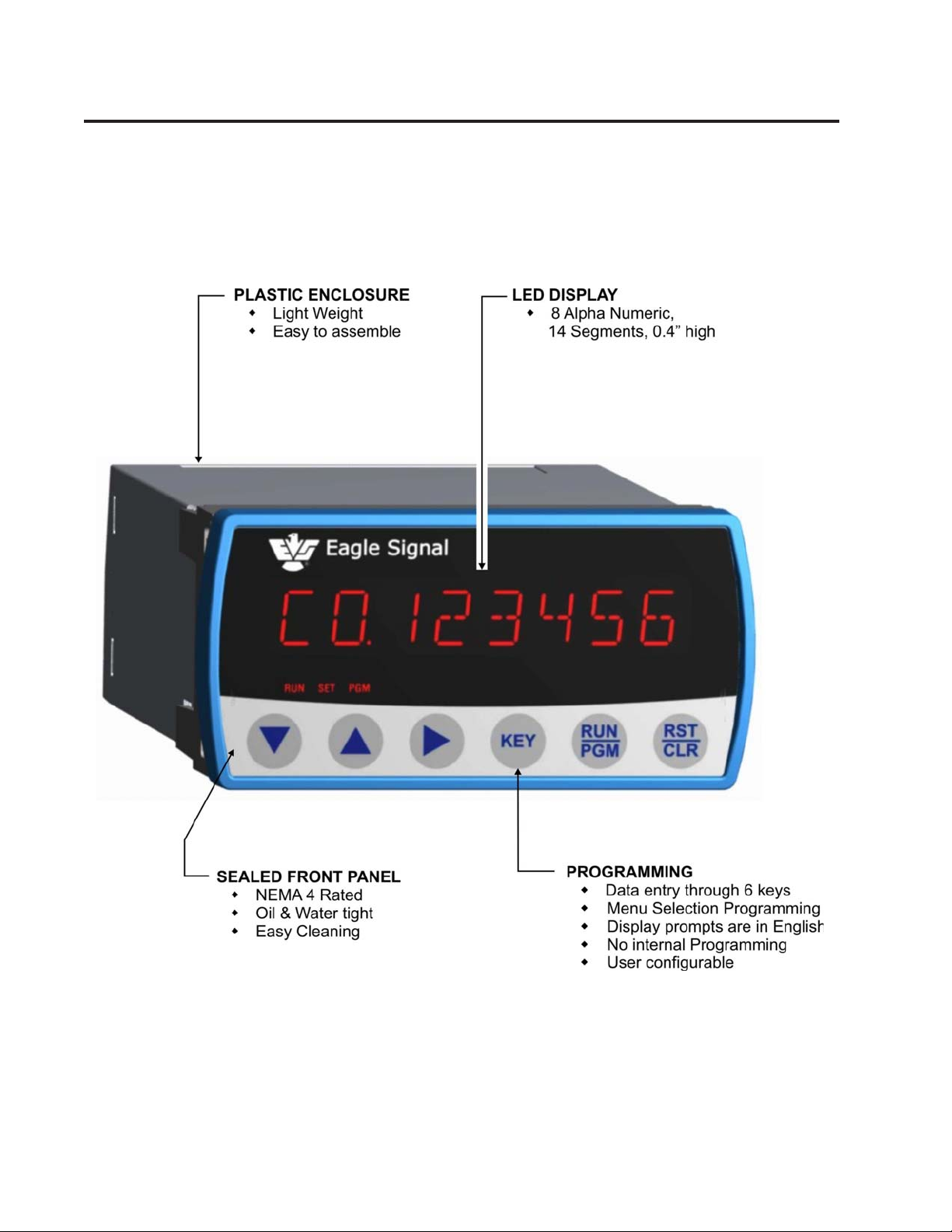
• Eight Alpha Numeric,14 Segments LED
display
KEY SPECIFICATIONS
• DC to 40kHz Operation
• Programmable Input Logic (x1,x2, or x4)
• Five Decade Calibrator
• Three Relay and Three Transistor Outputs
• 10Amp Relay Contact Rating
• Programmable Relay Hold Time xx.xx sec
• +12VDC @ 175mA Transducer Supply
• 85-265 VAC Operation (12VDC Optional)
OVERVIEW ...
Page 2

SPECIFICATIONS ...
Page 4
Input Power: 85-265 VAC, 50-60Hz, 20 V A
12 VDC @ 0.5 A. Optional
Accessory Supply: 12 VDC @ 175 mA.
Main Counter:
Range: 6 Decades
Presets: 3 Individual with 6 decade range
Operation: A-B, A+B, Quadrature
Reset Input: External and front panel
Count Rate: 40 kHz internal
(40kHz external input frequency
with x1 logic)
(20 kHz external input frequency
with x2 logic)
(10 kHz external input frequency
with x4 logic)
Calibrator:
Range: 5 Decade, 0.0001 to 9.9999
Operation: Calibrates Main Counter and
totalizer
Totalizer:
Range: 6 Decade
Operation: Totalizes calibrated input count s
Batch Counter:
Range: 6 Decade
Presets: 1 with 6 Decade range
Operation: Count UP by detecting Auto
Resets of main counter .
Output: Programmable assignment
Signal A and B Inputs:
Input Frequency: DC to 40kHz,
(40kHz external input frequency
with x1 logic)
(20 kHz external input frequency
with x2 logic)
(10 kHz external input frequency
with x4 logic)
Input Type: Single ended, Current Source
Input Logic: x1,x2,x4
Input High Level: 3.25 VDC min.
Input Low Level: 1.75 VDC max.
Input Impedance: 1.0 kΩ to common
Input current: 3.25mA. steady state
Input Response: 10µs. min high and low time
Control Inputs:
Input Frequency: DC to 20Hz Max. each input.
RESET input 100Hz response
Input Type: Single ended, current sinking
Input Logic: Both edge & Level sensitive as
defined by input use
Input High Level: 10VDC min. to 20 VDC max.
Input Low Level: 0 VDC min. to 2 VDC max.
Input Impedance: 4.7 kΩ pullup to +12 Vdc
Input Current: 2.5 mA. S teady state
Input Response: 25 ms. make and break time
Display:
Decades: Eight Alpha Numeric, 0.4" red LED
Annunciators: Three Annunciators RUN, SET, PGM
Decimal Point: User programmable
Range: x.xxxxx to xxxxxx
Keyboard: Sealed tactile feel, 6 positions
Program Security: Program LOCK for lines 3-39
Control Outputs:
Type: 3 Solid State,
100mA sink max., 24 VDC max.
Optional: 3 SPDT Relays, rated
10Amp 30VDC/270VAC Resistive
Serial Interface:
Type: RS-485 compatible (4 or 2
wire options with modbus support)
Baud Rate: Selectable; 1200, 2400, 4800 or 9600
Data: Binary
Format: 1 START Bit, 8 Bit data , 1 STOP Bit
Protocol: ModBus RTU
I.D. Number: Programmable 1 to 32: Allows
multidrop systems.
Diagnostics:
Test 0: Keyboard Test
Test 1: FRAM Test
Test 2: Input Test
Test 3: Output Test
Test 4: Display Test
Test 5: Flash Memory Test
Test 6: Date Code Test
Test 7: Serial I/O Test
Test 8: Return to Factory Programming
Mechanical:
Enclosure Plastic Moulded
2.0” High x 4.0 Wide x 5.56”Deep
Cutout 1.77”[ 45mm] x 3.62” [92mm]
Panel Thickness 1/16” to 1/4”
Panel Depth 5.68” Minimum
Weight 0.68 lb [308 gm]
Environmental:
Operating Temp: -15°C to +65°C
Storage Temp: -30°C to +85°C
Ambient Humidity: 90% and noncondensing
Controller Error Codes
1. Low AC Line Voltage ( Displays LOW AC)
2. Input Frequency Too fast (Displays FREQ MAX)
Pess To clear Error Code
FRAM Error Codes
1. Run Mode parameters corrupted (FRUNFAIL).
2. Program Mode parameters corrupted (FPGMFAIL).
Note: Power cycle to clear the FRAM error

ORDERING INFORMATION ...
CM 0 3 0 1
Optional Outputs
1 = 3 Solid State Outputs
2 = 3 Solid State & 3 Relay Outputs
Communication Options
1 = 2 Wire RS485
2 = 4 Wire RS485
3 = Ethernet - Modbus TCP/IP
Input Power Supply Options
1 = Universal Power Supply 85 - 265 VAC
2 = 12 VDC
1
0
 Loading...