

Introduction
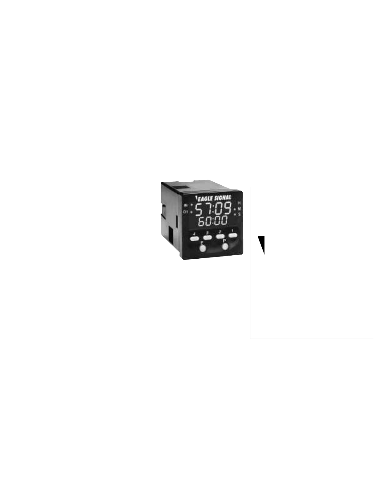
The precision of digital setting, versatile functionality and a straightforward button
per digit interface with a high visibility LED can all be found in the Eagle Signal
brand B506. Housed in a compact 1/16 DIN package, the B506 can be programmed
to perform a variety of standard timing operations as well as a unique On/Delay
Interval Mode which, in many cases, perfor ms the functions of two separate timers.
Five selectable time ranges and a programmable decimal point enable preset times
ranging from .01 seconds 9999 hours.
Inside this manual you will find complete information on the basic operation of the
timer, including inputting setpoints and viewing the process time and status
annunciators. The Program Mode section contains instructions on how to set the
basic configuration (i.e. mode of operation, time range) of the timer as well as other
settable features which enhance the functionality and usability of the device.
Also found in this manual are detailed timing diagrams and descriptions of the
available operating functions to aid you
in determining how to properly configure
the unit to solve your application.
Additionally included are key product
specifications, warranty procedures and
ordering information should you need
additional units or accessories.
If you require any additional assistance
with the installation and operation of
this product, please call our toll free
application support line at 1-800-234-
8731.
Overview
Panel Mounting page 2
Wiring Connections page 2
Front Panel Operation page 3
Programming
Program Mode page 4-5
Operating Modes
Timing Diagrams page 6
General
Specifications page 7
Ordering Information page 7
Warranty page 8
Technical Manual
702119-0001
B506
Multifunction
LED Timer
IndexFeatures
• Field programmable for one of 5 operating
modes
• 5 selectable time ranges with resolution
down to 0.01 seconds
• High Visibility display indicates both
process time and preset value
• Simple button per digit interface
• Programmable security levels prevent
unauthorized setpoint or program changes
• Universal AC Power Supply (90 - 264 VAC)
and low voltage (24 VAC/VDC) models
available
• External Start and Reset Inputs
• IEC IP65 rated front panel
• Industry standard 11 pin socket
connection
Eagle Signal
brand
2
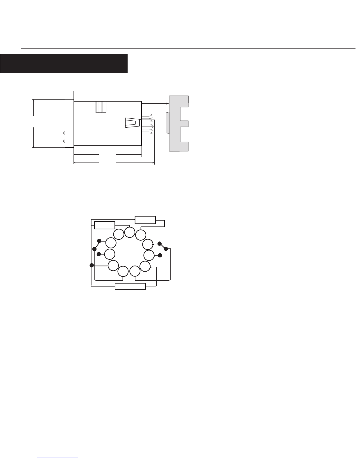
INSTALLATION & WIRING
O V E R V I E W
To wire the unit, an 11 pin socket is required. The
unit can either be DIN rail mounted or panel
mounted using the supplied mounting bracket.
For panel mounting, place the unit in the cutout,
then slide the bracket forward over the rear of the
unit so that the tabs catch in the grooves on the
housing and the bracket is as far forward as
possible. Tighten the panel mount screws until
there is a snug fit against the panel. Do not
overtighten.
48mm
8mm
66mm
81mm
1
11
2
3
4
5
6
7
8
9
10
Reset
Start
Warning: Do Not connect a coil in parallel
with the start signal for the B506. Such a
connection will cause the start signal to be
continuously active. This situation also
applies to the Reset input.
Power
3
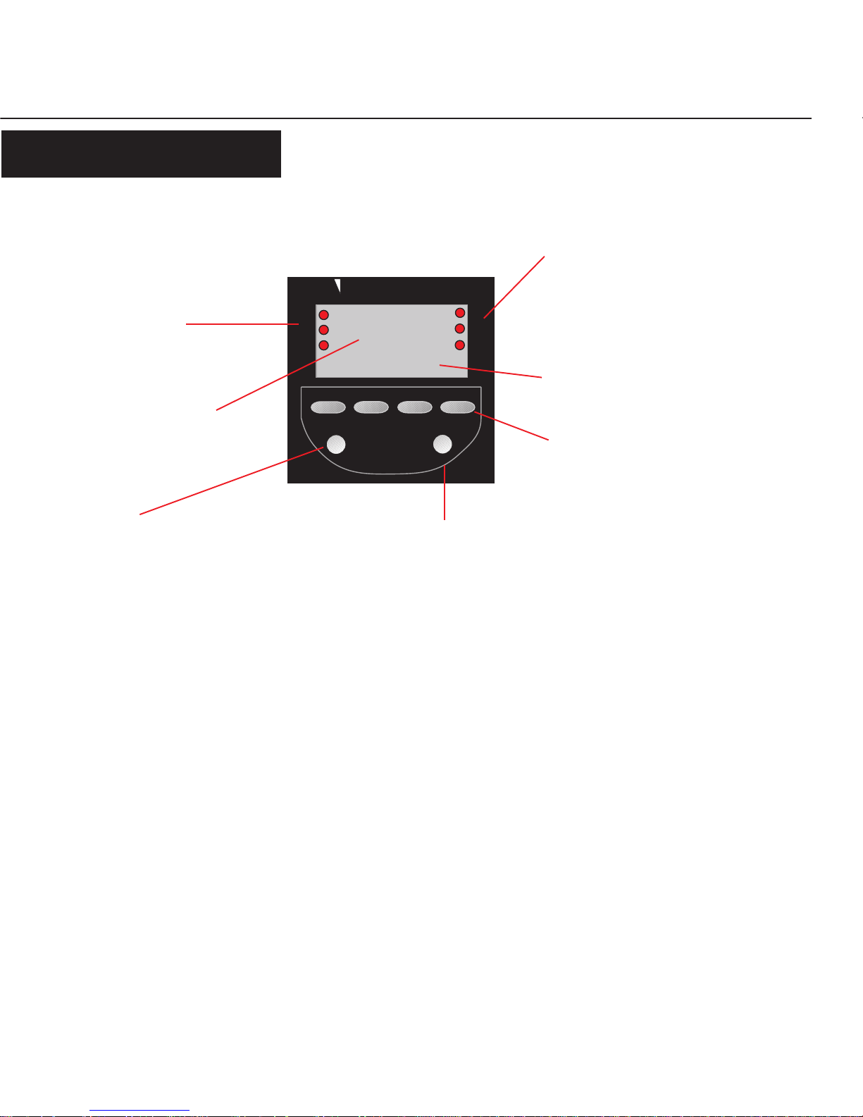
O V E R V I E W
FRONT PANEL OPERATION
4 3 2 1
EAGLE SIGNAL
E
P
1234
1234
H
M
S
IN
O1
O2
Time Range Indicator
Illuminates to show the time base: H for
hours, M for minutes, S for seconds.
Multiple indicators will be illuminated
when the time base is Hours:Minutes or
Minutes:Seconds.
Program Key
In Control Mode: Depressing the key will scroll the display
among the preset and batch displays. Holding the key down for
3 seconds will shift the unit into Program Mode. With the "E"
key, resets the displayed value
In Program Mode: Depressing the key will scroll the display
from one parameter to the next. Holding the key down for 3
seconds will shift the unit to Control Mode.
In Control Mode: With "P" key, resets the displayed value.
In Program Mode: Scrolls between the applicable choices for the
currently displayed parameter.
Each of the number keys is used to
increment the value of the
corresponding digit of the preset or a
parameter value
Numeric Keys
Set Value
Settable value used to trigger the
timed output.
Illuminates to display when an input or output
is active: "IN' for the start input, "O1" and
"O2" for the timed outputs.
I/O Status Indicators
Time Value
Indicates the elapsed/remaining time to
preset.
Edit Key

4
P R O G R A M M I N G
For 3 Seconds
P
Operating Function: Determines how outputs will operate in relation to the set value. Choices
are:
• On-Delay (OndL)
• Off Delay (OFdL)
• Interval (int)
• Repeat Cycle (CYCL)
• Delay/Interval (dint)
P
F u n c
O n d L
P
P
P
• Enter the Program Mode by holding down the "P" key for 3 seconds
• Press the "P" key to move the top display from one parameter to the next
• Press the "E" key to scroll the bottom display through the available choices for that parameter
• While in Program Mode, the unit will reset; the new settings will only become effective after
returning to Control Mode by holding down the "P" key for 3 seconds
• If there is no key activity for 60 seconds, the unit will automatically return to Control Mode and
continue to run under the previous settings
PROGRAM MODE
F r S t
O n
i n t
1 . 0
S
t r n G
d E c P
First Operation: Determines whether the Repeat Cycle will start with an On or an Off Operation.
See Page 6 for timing charts.
Note: The following parameter will only appear if Repeat Cycle is chosen as the
Operating Function.
Interval Time: Sets the amount of time the output will be active after the On-Delay function has
timed out. Use the 1 through 4 keys to set the value in a range from 0.1 to 999.9 seconds.
Note: The following parameter will only appear if Delay/Interval is chosen as the
Operating Function.
Time Range: Sets the unit of measure for the time values that will be shown on the display in
Control Mode. Choices are:
• Seconds
• Minutes
• Hours
• Minutes:Seconds
• Hours:Minutes
Decimal Position: Sets the decimal position for the time display. Choices are: no decimal point
(0), 10ths position (0.0), or Hundreths position (0.00). The time range selected in the previous
parameter will remain illuminated for reference.
Note: The following parameter will not appear if Minutes:Seconds or Hours:Minutes
is selected as the time range.

5
P R O G R A M M I N G
P
Timing Direction: Determines whether the time value will increment from zero and change the
state of the output at the set value (uP) or decrement from the set value and change the state of
the output at zero (dn).
P
Power Reset Enable: After a loss of power the unit can be programmed to either reset upon
reapplication of power (On) or continue from the point of power interruption (Off).
P
Front Panel Reset Enable: When active (On), the timing operation can be reset in Control Mode
by simultaneously pressing the "E" and "P" keys. If inactive (Off), the timing operation can only
be reset through the remote input.
Security Level: 4 different levels of security are available:
0 = Full Access
1 = SP Locked Out
2 = Access to Program Mode only by holding the "P" key for 10 seconds
3 = SP Locked Out and access to Program Mode only by holding the "P" key for 10
seconds
P
t d i r
u P
P r S t
O n
F r S t
O n
S L u L
0

6
O P E R A T I N G M O D E S
TIMING DIAGRAMS
Timing begins on the leading edge of the start input. The output will
activate at the completion of the preset time (T) and will remain active
until the reset signal is applied or power is interrupted*.
The output is activated at the leading edge of the start signal. Timing
begins on the trailing edge. The output will remain active until the preset
time (T) has elapsed or power is interrupted*. Reapplying the start signal
before T has elapsed will reset the time value. The reset input is not used.
Timing begins on the leading edge of the start signal. A cycle is initiated
where the output will be OFF for the preset time (T), then ON for the preset
time. This cycle will continue until the start signal is removed, a reset
signal is applied or power is interrupted*. The unit can also be programmed
for the timing sequence to begin with an ON cycle.
On the leading of the start input, the output is activated and timing
begins. The output will remain active until the preset time (T) has
elapsed, the reset signal is applied or power is interrupted*. Removal
of the start signal will also cause the output to be deactivated and the
time value reset.
T1
T2
Power
Reset
Output
Start
ON Delay/Interval
The delay cycle begins upon application of the start signal. The
output will activate at the completion of the preset time (T1). Upon
activation of the output the Interval cycle will begin. The output will
be deactivated at the and the end of the Interval time (T2). T1 is the
primary preset value and is set in Operation Mode. T2 is set in
Program Mode in a range from 0.1 to 999.9 seconds. The timing
sequence and output can also be reset through the reset input or
interuption of power*.
* The Power Reset parameter in Program Mode can be set so
that a timing sequece will not be reset upon power
interruption but instead continue on when power is restored.
Repeat Cycle
T
T
T
Output
Start
Power
Reset
T
T
Off-Delay
Output
Start
Power
T
T
Interval
Power
Output
Start
On-Delay
T
Output
Reset
Start
Power

7
SPECIFICATIONS
ORDERING INFORMATION
G E N E R A L
Operation
Supply Voltage: 90 - 240 VAC 50/60Hz, or 24 VAC/VDC
Power Consumption: < 10 VA
Time Ranges: Hours, Minutes, Seconds, Hours:Minutes,
Minutes:Seconds
Resolution: Settable for XXXX or XX.XX for Hours,
Minutes and Seconds ranges
Operating Modes: On Delay, Off Delay, Interval, Repeat,
Delay/Interval
Repeat Accuracy:
+ 0.01%
Electrical Service Life: 100,000 cycles at full load
Mechanical Service Life: 10 million cycles at min. load
Weight: 100 grams (3.5 ounces)
Environmental
Front Panel Rating: IEC IP65
Operating Temperature: 0° to 55° C (32° to 131° F)
Storage Temperature: -40° to 90° C (-40° to 194° F)
Humidity: 5% to 95% RH non-condensing
Approvals: UL, CUL recognized - File #97337, CE
certified
Inputs
Start: NPN or Dry Contact
Reset: NPN or Dry Contact
Activation Time: 4 ms (B506-5XX2), 21 ms (B506-
5XX1)
Impedance: 10 KΩ
Outputs
Timed: DPDT (5 amp)
Physical
Dimensions: 48mm x 48mm, 85mm deep
Mounting: Panel Mounting 45mm x 45mm
cutout, or DIN rail
Wiring Connection: Via 11 pin plug in socket
Description Model #
Multi-function Timer, 90- 240 VAC B506-5001
Multi-function Timer, 24 VAC/VDC B506-5002
Description Model #
11 Pin Socket 60SR3P06
11 Pin Socket - Outward facing terminals PBT -03172

8
Printed in U.S.A.
#702119-0001
Sept 1997
Revision none
1675 Delany Road
Gurnee, IL 60031–1282
Phone: 847.662.2666
Fax: 847.662.6633
Danaher Controls
G E N E R A L
Standard B506 products manufactured by the Company are
warranted to be free from defects in workmanship and material for a
period of two years from the date of shipment, and products which
are defective in workmanship or material will be repaired or
replaced, at the option of the Company, at no charge to the Buyer.
Final determination as to whether a product is actually defective
rests with the Company. The obligation of the Company hereunder
shall be limited solely to repair and replacement of products that
fall within the foregoing limitations, and shall be conditioned upon
receipt by the Company of written notice of any alleged defects or
deficiency promptly after discovery within the warranty period, and
in the case of components or units purchased by the Company, the
obligation of the Company shall not exceed the settlement that the
Company is able to obtain from the supplier thereof. No products
shall be returned to the Company without its prior consent.
Products which the Company consents to have returned shall be
shipped F.O.B. the Company's factory. The Company cannot assume
responsibility or accept invoices for unauthorized repairs to its
components, even though defective. The life of the products of the
Company depends, to a large extent, upon the type of usage thereof,
and THE COMPANY MAKES NO WARRANTY AS TO FITNESS OF ITS
PRODUCTS FOR SPECIFIC APPLICATIONS BY THE BUYER NOR AS
TO PERIOD OF SERVICE UNLESS THE COMPANY SPECIFICALLY
AGREES OTHERWISE IN WRITING AFTER THE PROPOSED USAGE
HAS BEEN MADE KNOWN TO IT.
THE FOREGOING WARRANTY IS EXCLUSIVE AND IN LIEU OF ALL
OTHER WARRANTIES EXPRESSED OR IMPLIED, INCLUDING, BUT
NOT LIMITED TO ANY WARRANTY OF MERCHANTABILITY OR OF
FITNESS FOR A PAR TICULAR PURPOSE.
WARRANTY
 Loading...