

Eagle Group 168EX, 128 PORTABLE, 168, 128 User Manual
www.eaglesonar.com
Pub. 988-0143-631
Cuda 128, Cuda 128 Portable,
Cuda 168, Cuda 168EX
Fish-finding & Depth Sounding Sonars
Installation and Operation
Instructions

Copyright © 2002 Eagle Electronics
All rights reserved.
®
Eagle
is a registered trademark of Eagle Electronics
Marine-Tex is a trademark of Illinois Tool Works Inc.
Eagle Electronics may find it necessary to change or end our policies,
regulations, and special offers at any time. We reserve the right to do so
without notice. All features and specifications subject to change without
notice. All screens in this manual are simulated.
For free owner's manuals and other information,
visit our web site:
www.eaglesonar.com
Eagle Electronics
P.O. Box 669
Catoosa, OK USA 74015
Printed in USA.

Table of Contents
Introduction ...............................................................................1
Capabilities and Specifications: Cuda Family ......................... 1
Installation Preparations ............................................................. 3
Transducer Installation...........................................................4
Recommended Tools and Supplies ........................................... 4
Selecting a Transducer Location.............................................. 5
Shoot-Thru-Hull vs. Transom Mounting ................................. 7
Transom Transducer Assembly and Mounting ....................... 7
Trolling Motor Bracket Installation....................................... 12
Transducer Orientation and Fish Arches .............................. 12
Shoot-Thru-Hull Preparation and Installation ..................... 14
Power and Cable Connections.................................................... 16
Mounting the Sonar Unit: In-Dash or Bracket ......................... 18
In-Dash Installation ............................................................... 18
Bracket Installation................................................................ 21
Portable Sonar Installation........................................................ 25
Operation .................................................................................. 30
Keyboard Basics.......................................................................... 30
PWR/Clear (Power and Clear)................................................30
Menu Up and Menu Down ..................................................... 30
Up and Down Arrows.............................................................. 31
Memory........................................................................................ 31
Menus .......................................................................................... 31
Display – Opening Screen ..........................................................32
Chart Scroll (Stopping and Starting)......................................... 33
Full Chart.................................................................................... 34
Depth Range Zoom (Automatic and Manual)............................ 35
Zoom ............................................................................................36
Sensitivity ...................................................................................37
Grayline
Fish I.D. ................................................................................... 41
®
..................................................................................... 40
i

FishTrack™................................................................................. 43
Chart Scroll Speed ...................................................................... 44
Noise Reject and ASP (Advanced Signal Processing) ............ 44
Alarms ......................................................................................... 45
Fish Alarm............................................................................... 45
Depth Alarms .......................................................................... 46
Shallow Alarm......................................................................... 46
Deep Alarm ............................................................................. 46
Display Adjustments .................................................................. 47
Backlights................................................................................ 47
Display Contrast ..................................................................... 47
Depth Units of Measure ............................................................. 48
Preset Unit (Reset All Options).................................................. 48
System Info ................................................................................. 48
Simulator..................................................................................... 48
Digital Data Size for Depth and Temperature.......................... 49
Troubleshooting ......................................................................50
Warranty and Service Information.....................................57
ii

Introduction
Thank you for buying an Eagle sonar! Your unit is a high-quality
sonar designed for both professional and novice fishermen. All Eagle
sonars have an automatic mode that finds and displays the bottom,
fish, underwater structure and more – right out of the box. All you have
to do is press the on (
However, if you want to fine-tune your unit, press the
sonar has several powerful features you can control by scrolling through
easy-to-use menus with the arrow and menu keys.
To get started with your Eagle sonar, first read the installation section.
It contains instructions for mounting the sonar unit and the transducer.
Following recommended installation practices will pay off in optimum
performance of your Eagle sonar. Improper installation can cause
problems down the road, especially if the transducer is badly mounted.
After you've read the installation instructions, install the unit and
accessories. Then, read the rest of the manual. The more you know
about your sonar, the better it will work for you.
Take advantage of the Simulator feature. It allows you to practice
operating your sonar before you get it in the water. And when you finally
head for your favorite fishing hole, take this manual along for reference.
Capabilities and Specifications: Cuda Family
Case size: .......................... Cuda 128 and Cuda 168: 5.8" H x 4.3" W x
Display:............................ High-contrast Film SuperTwist LCD.
) key.
PWR
MENU UP
General
2.5" D (14.7 cm H x 10.8 cm W x 6.6 cm D).
Cuda 168EX: 5.4" H x 6.9" W x 3.4" D (13.8
cm H x 17.6 cm W x 8.6 cm D).
Sealed, waterproof; suitable for saltwater use.
Diagonal viewing area:
Cuda 128 and Cuda 168: 4.0" (10.2 cm).
Cuda 168EX: 4.5" (11.4 cm).
1
key. The

Resolution:...................... Cuda 128 and Cuda 128 Portable:
128 pixels (vert.) x 65 pixels (horiz.)
resolution; 8,320 total pixels.
Cuda 168 and Cuda 168 EX:
168 pixels (vert.) x 132 pixels (horiz.)
resolution; 22,176 total pixels.
Backlighting:.................. Backlit screen and keypad for night use.
Input power:................... 10 to 17 volts DC.
Current drain: ............... 110 ma lights off; 250 ma lights on.
Back-up memory: .......... Built-in memory stores sonar settings when
unit is turned off.
Sonar
Frequency:...................... 200 kHz.
Transducers: .................. A Skimmer
transducer comes packed with
your sonar unit. Its 20° cone angle offers a
wide fish detection area of up to 60º with
high sensitivity settings. Operates at boat
speeds up to 70 mph (61 kts).
Transmitter: ................... 800 watts peak-to-peak; 100 watts RMS.
Sonar sounding
depth capability: ........... 600 feet (180 meters). Actual capability
depends on transducer configuration and
installation, bottom composition and water
conditions. All sonar units typically read
deeper in fresh water than in salt water.
Depth display:................ Continuous digital readout.
Audible alarms: ............. Deep/shallow/fish.
Automatic ranging:....... Yes.
Auto bottom track:........ Yes.
Zoom bottom track: ...... Yes.
Surface water temp: ..... Yes.
2

NOTICE!
The storage and operation temperature range for your unit is from
-4 degrees to +167 degrees Fahrenheit (-20 degrees to +75 degrees
Celsius). Extended storage or operation in temperatures higher or
lower than specified will damage the liquid crystal display in your
unit. This type of damage is not covered by the warranty. For more
information, contact the factory's Customer Service Department;
phone numbers are inside the manual's back cover.
Installation Preparations
You can install the sonar system in some other order if you prefer, but
we recommend this installation sequence:
Caution:
You should read over this entire installation section before
drilling any holes in your vessel!
1. Determine the approximate location for the sonar unit, so you can
plan how and where to route the cables for the transducer and power.
This will help you make sure you have enough cable length for the
desired configuration.
2. Determine the approximate location for the transducer and its cable
route.
3. Determine the location of your battery or other power connection,
along with the power cable route.
4. Install the transducer and route the transducer cable to the sonar
unit.
5. Install the power cable and route it to the sonar unit.
6. Mount the sonar unit.
3

Transducer Installation
These instructions will help you install your Skimmer
transom, on a trolling motor or inside a hull. Please read all
instructions before proceeding with any installation.
Your Skimmer transducer typically comes packaged with a one-piece
stainless steel bracket for mounting it to the transom of your boat. The
optional trolling motor mount uses a one-piece plastic bracket with an
adjustable strap. These are "kick-up" mounting brackets. They help
prevent damage if the transducer strikes an object while the boat is
moving. If the transducer does "kick-up," the bracket can easily be
pushed back into place without tools.
Read these instructions carefully before attempting the installation.
Determine which of the installation methods is right for your boat.
Remember, the transducer installation is the most critical part
of a sonar installation.
Recommended Tools and supplies
If you prefer the option of routing the cable through the transom, you will
need a 5/8" drill bit. The following installation types also call for these
recommended tools and required supplies (supplies are not included):
Transom installation
Tools include: two adjustable wrenches, drill, #29 (0.136") drill bit, flathead screwdriver. Supplies: high quality, marine grade above- or belowwaterline caulking compound.
Trolling motor installations
Tools: two adjustable wrenches, flat-head screwdriver. Supplies: plastic
cable ties.
Shoot-through hull installations
Tools: these will vary depending on your hull's composition. Consult your
boat dealer or manufacturer. Supplies: 100 grit sandpaper, good quality
epoxy adhesive.
4
transducer on a

Selecting a Transducer Location
1. The transducer must be placed in a location that has a smooth flow of
water at all times. If the transducer is to be mounted inside the hull,
then the chosen location must be in the water at all times. If the
transducer is not placed in a smooth flow of water, interference
caused by bubbles and turbulence will show on the sonar's display in
the form of random lines or dots whenever the boat is moving.
NOTE:
Some aluminum boats with strakes or ribs on the outside of the
hull create large amounts of turbulence at high speed. These boats
typically have large outboard motors capable of propelling the boat
at speeds faster than 35 mph. Typically, a good location on
aluminum boats is between the ribs closest to the engine.
2. The transducer should be installed with its face pointing straight
down, if possible.
3. If the transducer is mounted on the transom, make sure it doesn't
interfere with the trailer or hauling of the boat. Also, don't mount it
closer than approximately one foot from the engine's lower unit. This
will prevent cavitation (bubble) interference with propeller operation.
4. If possible, route the transducer cable away from other wiring on the
boat. Electrical noise from engine wiring, bilge pumps and aerators
can be displayed on the sonar's screen. Use caution when routing the
transducer cable around these wires.
5
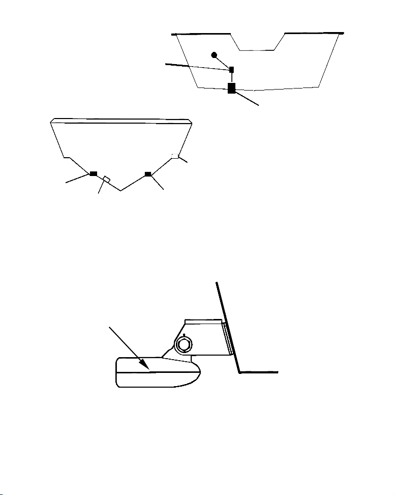
CAUTION: Clamp the
transducer cable to transom
near the transducer. This will
help prevent the transducer
from entering the boat if it is
knocked off at high speed.
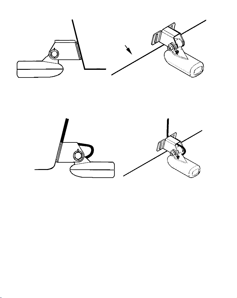
Good location
Poor location
Good
location
Poor angle
Good and poor transducer locations.
Good location
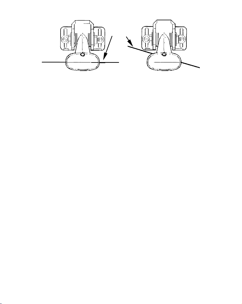
How low should you go?
For most situations, you should install your Skimmer transducer so
that its centerline is level with the bottom of the boat hull. This will
usually give you the best combination of smooth water flow and
protection from bangs and bumps.
Transducer
centerline
Align transducer centerline with hull bottom.
Transom
Hull bottom
However, there are times when you may need to adjust the transducer
slightly higher or lower. (The slots in the mounting brackets allow you
6

to loosen the screws and slide the transducer up or down.) If you
frequently lose bottom signal lock while running at high speed, the
transducer may be coming out of the water as you cross waves or
wakes. Move the transducer a little lower to help prevent this.
If you cruise or fish around lots of structure and cover, your transducer
may be frequently kicking up from object strikes. If you wish, you may
move the transducer a little higher for more protection.
There are two extremes you should avoid. Never let the edge of the
mounting bracket extend below the bottom of the hull. Never let the
bottom – the face – of the transducer rise above the bottom of the hull.
Shoot-thru-hull vs. Transom Mounting
Typically, shoot-thru-hull installations give excellent high speed
operation and good to excellent depth capability. There is no possibility
of damage from floating objects. It can't be knocked off when docking or
loading on the trailer.
However, the shoot-thru-hull installation does have its drawbacks.
First, some loss of sensitivity does occur, even on the best hulls. This
varies from hull to hull, even from different installations on the same
hull. This is caused by differences in hull lay-up and construction.
Second, the transducer angle cannot be adjusted for the best fish
arches. This can be a problem on some hulls that sit with the bow high
when at rest or at slow trolling speeds. Follow the procedure listed in
the shoot-thru-hull installation section at the end of this lesson to
determine if you can satisfactorily shoot through the hull.
TRANSOM TRANSDUCER ASSEMBLY AND MOUNTING
The best way to install the transducer is to loosely assemble all of the
parts first, place the transducer's bracket against the transom and see if
you can move the transducer so that it's parallel with the ground.
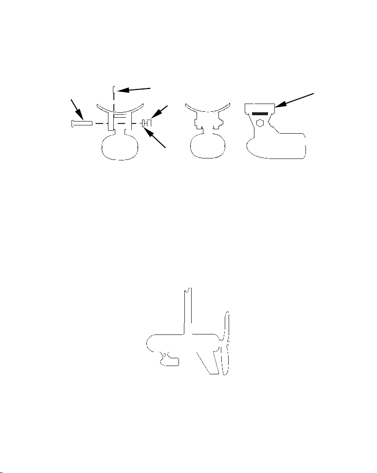
1. Assembling the bracket. Press the two small plastic ratchets into the
sides of the metal bracket as shown in the following illustration. Notice
7
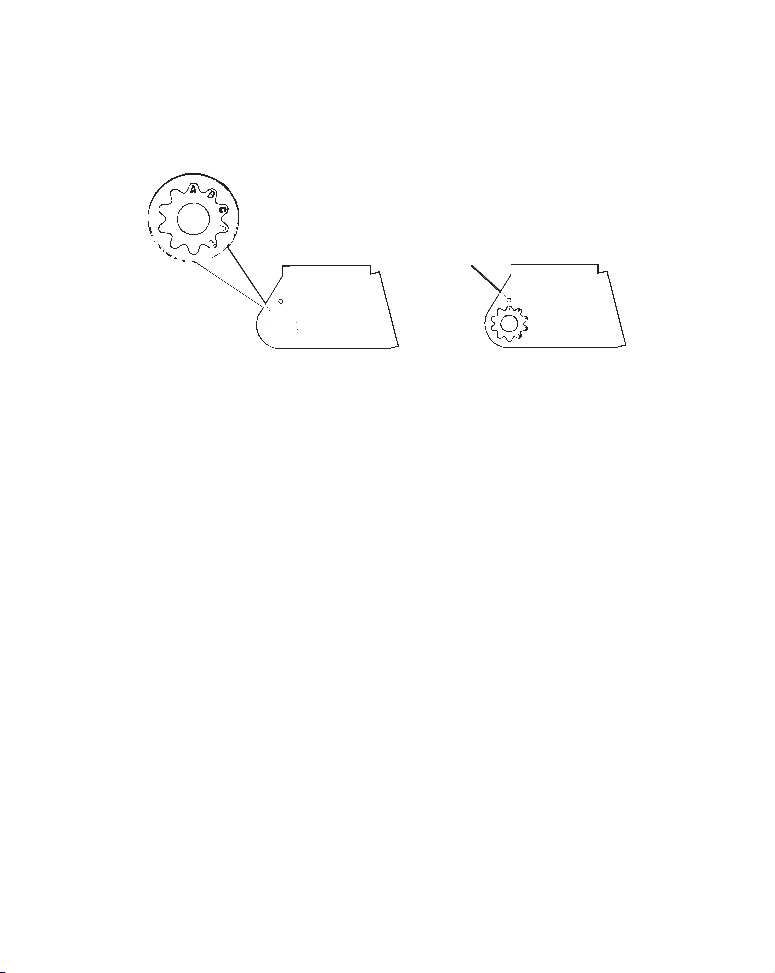
there are letters molded into each ratchet. Place each ratchet into the
bracket with the letter "A" aligned with the dot stamped into the metal
bracket. This position sets the transducer's coarse angle adjustment for a
14° transom. Most outboard and stern-drive transoms have a 14° angle.
Dot
Align plastic ratchets in bracket.
2. Aligning the transducer on the transom. Slide the transducer
between the two ratchets. Temporarily slide the bolt though the
transducer assembly and hold it against the transom. Looking at the
transducer from the side, check to see if it will adjust so that its face
is parallel to the ground. If it does, then the "A" position is correct for
your hull.
If the transducer's face isn't parallel with the ground, remove the
transducer and ratchets from the bracket. Place the ratchets into the
holes in the bracket with the letter "B" aligned with the dot stamped
in the bracket.
Reassemble the transducer and bracket and place them against the
transom. Again, check to see if you can move the transducer so it's
parallel with the ground. If you can, then go to step 3. If it doesn't,
repeat step 2, but use a different alignment letter until you can place
the transducer on the transom correctly.
8
Ratchets
Insert bolt and check transducer position on transom.
3. Assembling the transducer. Once you determine the correct
position for the ratchets, assemble the transducer as shown in the
following figure. Don't tighten the lock nut at this time.
Metal
Nut
washer
Rubber
washers
Assemble transducer and bracket.
Metal washer
Bolt
4. Drilling mounting holes. Hold the transducer and bracket assembly
against the transom. The transducer should be roughly parallel to the
ground. The transducer's centerline should be in line with the bottom
of the hull. Don't let the bracket extend below the hull!
Mark the center of each slot for the mounting screw pilot holes. You
will drill one hole in the center of each slot.
Drill the holes using the #29 bit (for the #10 screws).
9
Transom
Transom
Position transducer mount on transom and mark mounting holes.
Side view shown at left and seen from above at right.
5. Attaching transducer to transom. Remove the transducer from
the bracket and re-assemble it with the cable passing through the
bracket over the bolt as shown in the following figures.
Route cable over bolt and through bracket. Side view shown at left and
seen from above at right.
Attach the transducer to the transom. Slide the transducer up or
down until it's aligned properly with the bottom of the hull as shown
in the preceding and following figures. Tighten the bracket's
mounting screws, sealing them with the caulking compound.
Adjust the transducer so that it's parallel to the ground and tighten
the nut until it touches the outer washer, then add 1/4 turn. Don't
over tighten the lock nut! If you do, the transducer won't "kick-up" if
it strikes an object in the water.
10
Bottom
of
hull
Flat-bottom hull
Align transducer centerline with hull bottom and attach to transom.
Deep-"vee" hull
6. Route the transducer cable through or over the transom to
the sonar unit. Make sure to leave some slack in the cable at the
transducer. If possible, route the transducer cable away from other
wiring on the boat. Electrical noise from the engine's wiring, bilge
pumps, VHF radio wires and cables, and aerators can be picked up by
the sonar. Use caution when routing the transducer cable around
these wires.
WARNING:
Clamp the transducer cable to the transom close to the
transducer. This can prevent the transducer from
entering the boat if it is knocked off at high speed.
If you need to drill a hole in the transom to pass the connector through,
the required hole size is 5/8".
Caution:
If you drill a hole in the transom for the cable, make sure it is
located above the waterline. After installation, be sure to seal the
hole with the same marine grade above- or below-waterline
sealant used for the mounting screws.
7. Make a test run to determine the results. If the bottom is lost at
high speed, or if noise appears on the display, try sliding the
transducer bracket down. This puts the transducer deeper into the
water, hopefully below the turbulence causing the noise. Don't allow
the transducer bracket to go below the bottom of the hull!
11
TROLLING MOTOR BRACKET INSTALLATION
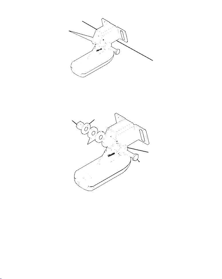
1. Attach the optional TMB-S bracket to the transducer as shown in the
following figure, using the hardware supplied with the transducer.
(Note: The internal tooth washer is supplied with the TMB-S.)
Bolt
Attach motor mounting bracket to transducer.
Internal tooth washer
Nut
Flat washer
TMB-S bracket
2. Slide the adjustable strap supplied with the TMB-S through the slot
in the transducer bracket and wrap it around the trolling motor.
Position the transducer to aim straight down when the motor is in
the water. Tighten the strap securely.
3. Route the transducer cable alongside the trolling motor shaft. Use
plastic ties (not included) to attach the transducer cable to the
trolling motor shaft. Make sure there is enough slack in the cable for
the motor to turn freely. Route the cable to the sonar unit and the
transducer is ready for use.
Transducer mounted on trolling motor, side view.
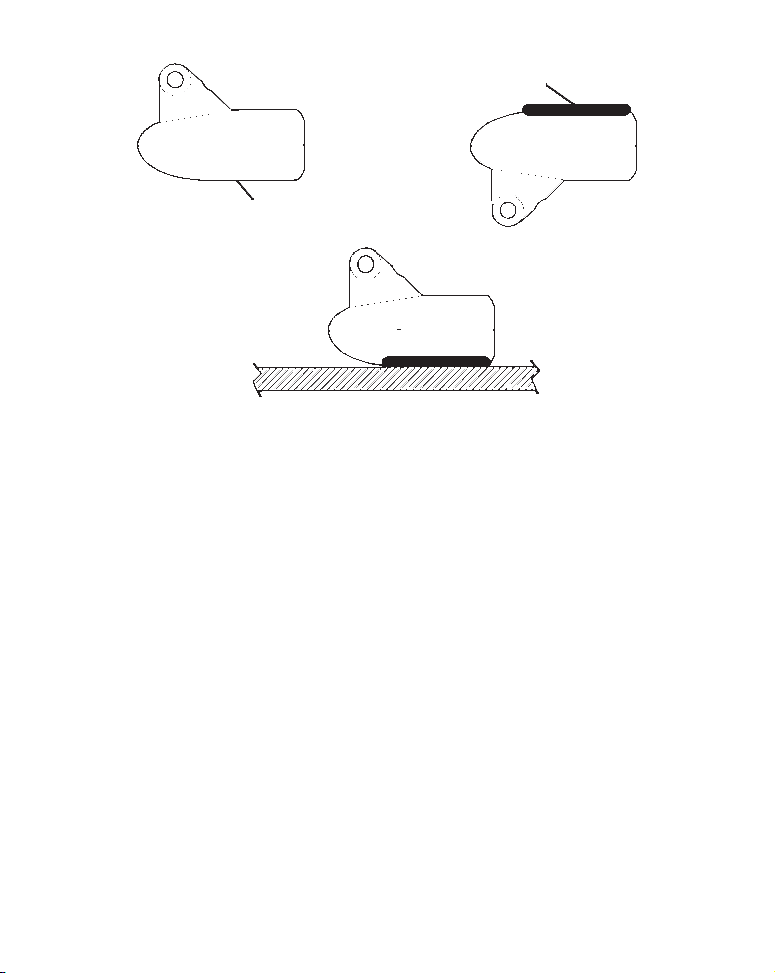
TRANSDUCER ORIENTATION AND FISH ARCHES
If you do not get good fish arches on your display, it could be because
12
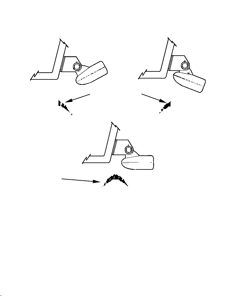
the transducer is not parallel with the ground when the boat is at rest
in the water or at slow trolling speeds.
Partial fish arches
Transducer aimed
too far back
Full fish arch
Transducer angles and their effects on fish arches.
Proper transducer angle
Transducer aimed
too far forward
If the arch slopes up – but not back down – then the front of the
transducer is too high and needs to be lowered. If only the back half of
the arch is printed, then the nose of the transducer is angled too far
down and needs to be raised.
NOTE:
Periodically wash the transducer's face with soap and water to
remove any oil film. Oil and dirt on the face will reduce the
sensitivity or may even prevent operation.
13
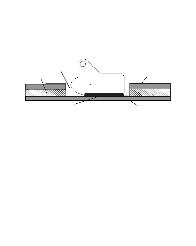
SHOOT-THRU-HULL PREPARATION
The transducer installation inside a fiberglass hull must be in an area
that does not have air bubbles in the resin or separated fiberglass
layers. The sonar signal must pass through solid fiberglass. A
successful transducer installation can be made on hulls with flotation
materials (such as plywood, balsa wood or foam) between layers of
fiberglass if the material is removed from the chosen area.
Fill with epoxy
Flotation material
Inner hull
Epoxy to hull first
Epoxy the transducer to a solid portion of the hull.
Outer hull
For example, some (but not all) manufacturers use a layer of fiberglass,
then a core of balsa wood, finishing with an outer layer of fiberglass.
Removing the inner layer of fiberglass and the balsa wood core exposes
the outer layer of fiberglass. The transducer can then be epoxied
directly to the outer layer of fiberglass. After the epoxy cures, the hull
is watertight and structurally sound. Remember, the sonar signal must
pass through solid fiberglass. Any air bubbles in the fiberglass or the
epoxy will reduce or eliminate the sonar signals.
WARNING:
Do not remove any material from your inner hull unless
you know the hull's composition. Careless grinding or
cutting on your hull can result in damage that could sink
your boat. Contact your boat dealer or manufacturer to
confirm your hull specifications.
To choose the proper location for thru-hull mounting, anchor the boat in
60 feet of water. Add a little water to the sump of the boat. Plug the
transducer into the sonar unit, turn it on, then hold the transducer over
the side of the boat. Adjust the sensitivity and range controls until a
14
second bottom echo is seen on the display. (You will need to turn off both
automatic and ASP.) Don't touch the controls once they've been set.
Next, take the transducer out of the water and place it in the water in
the sump of the boat. Observe the sonar signal to see if there is a
noticeable decrease in sensitivity. The second bottom signal may
disappear and the bottom signal may decrease in intensity.
Move the transducer around to find the best location. If the sensitivity
control must be increased greatly to compensate, then the transducer
should be mounted on the outside of the hull. If not, then mark the
location that shot through the hull the best and follow the instructions
on the following pages for a shoot-thru-hull mounting.
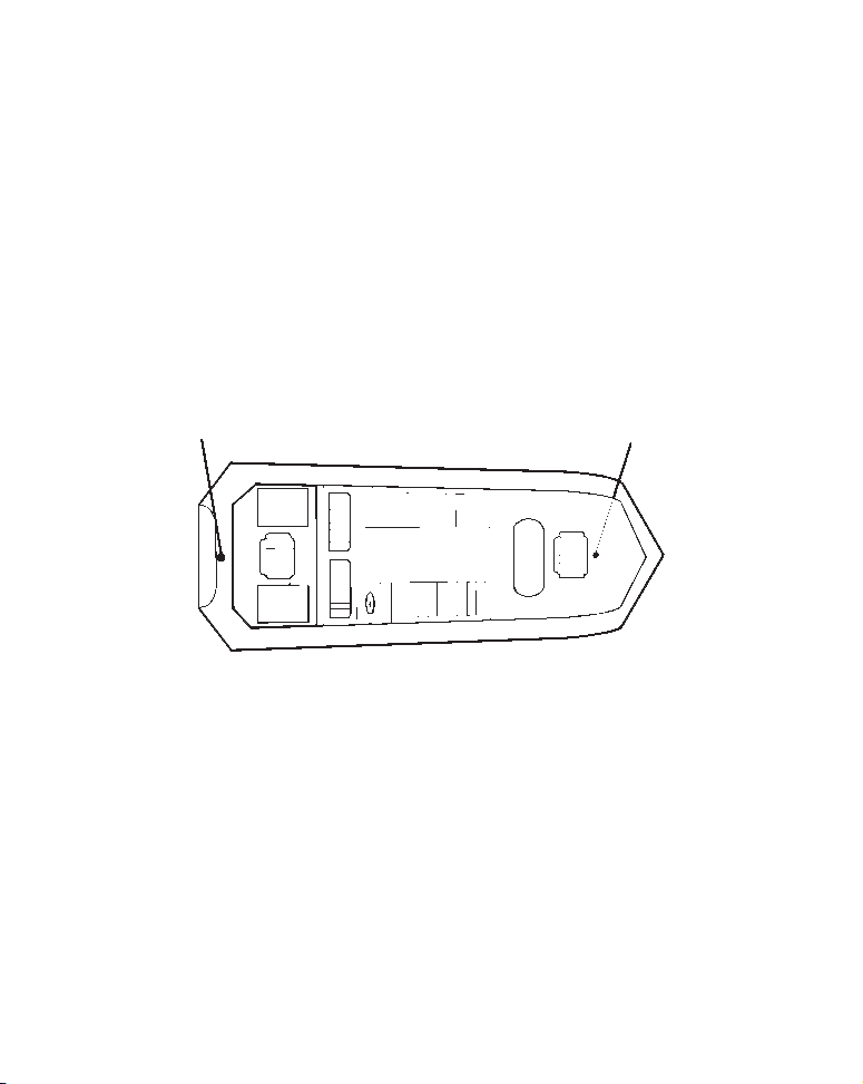
Transducer location
(high speed)
Shoot-thru-hull transducer locations for
high speed or trolling speed operation.
Transducer location
(trolling speed)
Shoot-thru-hull Installation
1. Make sure the area is clean, dry and free of oil or grease, then sand
both the inside surface of the hull and the face of the transducer with
100 grit sandpaper. The surface of the hull must be flat so the entire
transducer face is in contact with the hull prior to bonding.
15
Spread epoxy here
Sand this surface
Epoxy transducer to hull.
2. Follow the instructions on the epoxy package and mix it thoroughly.
Do not mix it too fast, because it will cause bubbles to form in the
epoxy. Apply a small amount on the face of the transducer as shown
above, then spread a small amount onto the sanded area on the hull.
Place the transducer into the epoxy, twisting and turning it to force
any air bubbles out from under the transducer face. The face of the
transducer should be parallel with the hull, with a minimum amount
of epoxy between the hull and transducer. After the epoxy dries,
route the cable to the sonar unit.
POWER AND CABLE CONNECTIONS
The unit works from a 12-volt battery system. For the best results,
attach the power cable directly to the battery. You can attach the power
cable to an accessory or power buss, however you may have problems
with electrical interference. Therefore, it's safer to go ahead and attach
the power cable directly to the battery.
16
 Loading...