

Eagle Access Control Systems X9S, X9L Installation & Owner's Manual
X9S & X9L
ACCESS CONTROL SYSTEMS, INC.
BY
EAGL
E
AC
CESS CONT
RO
L SYST
E
MS, INC.
TM
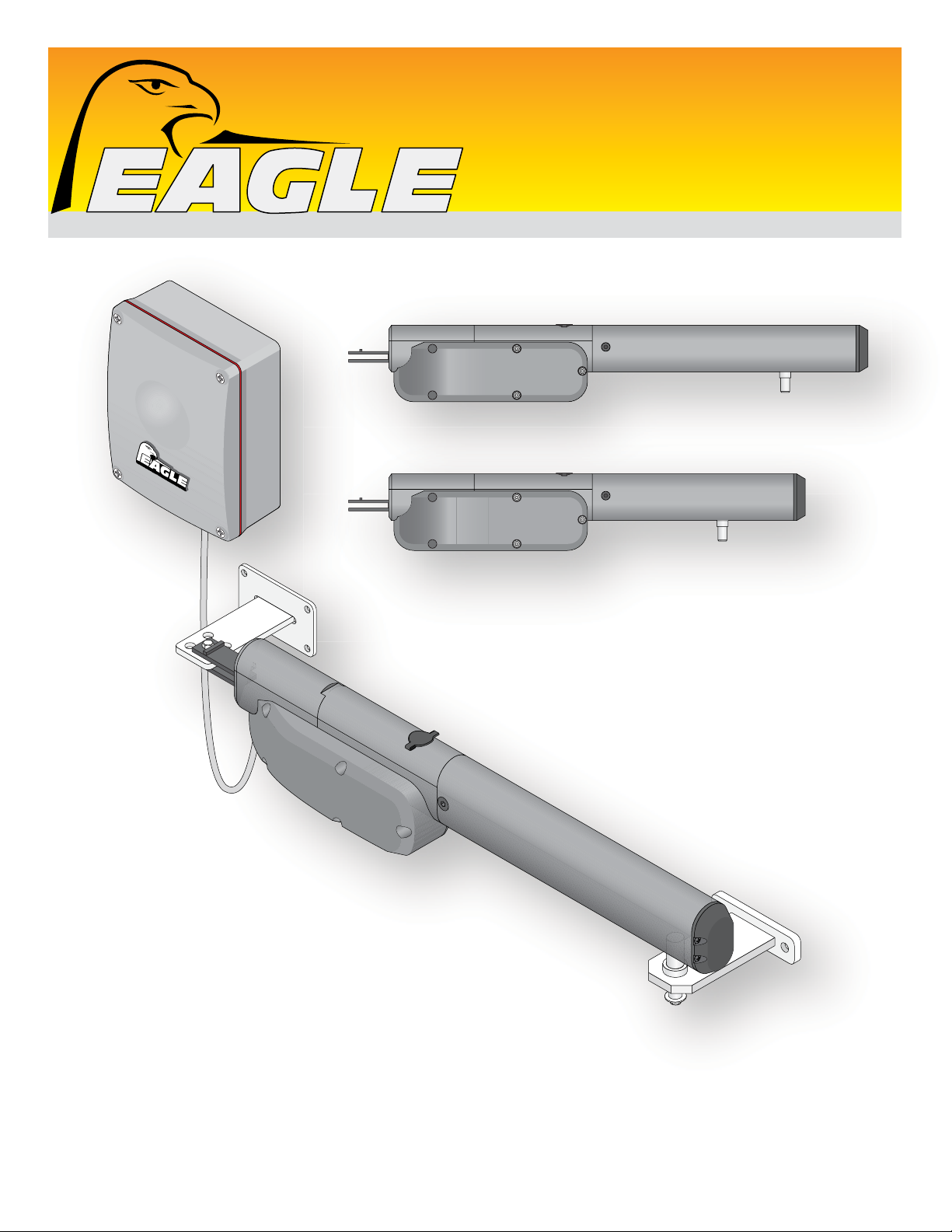
X9L - Long Arm
X9S - Short Arm
X9S & X9L
Swing Gate Operators
Gate Capacity 16 ft - 800 lbs.
Gate Capacity 10 ft - 700 lbs.
Installation & Owners Manual
AVI Slide Rev - C

2
X9 Swing Rev - H
ou
essed
publishe
spec
subjec
TABLE OF CONTENTS
UL 325 Listings
UL 325 Model Classifications
Swing Gate Recommendations
Important Safety Informatio
General Safety Information
Sample Single Gate Installation Setups
Sample Dual Gates Installation Setups
Disassemble Operator
Mount Arm
Mount Control Box
Open INSIDE Mounting Dimensions
Open OUTSIDE Mounting Dimensions
Adjusting Physical Limits
120 VAC Input Power Connection
Photo Eye Installation
Open INSIDE - Single Operator & Photo Eye Wiring
Open OUTSIDE - Single Operator & Photo Eye Wiring
Open INSIDE - Dual Operators & Photo Eye Wiring
Open OUTSIDE - Dual Operators & Photo Eye Wiring
Wiring Accessories
Advanced Accessory Connection
Loop Detectors
DIP-Switch Descriptions
n
INSTALLATION
SAFETY
2
2
3
4
5
5
6
6
7
8
9
10
11
12
13
13
14
15
16
17
18
19
20
21
22-23
PROGRAMMING & ADJUSTMENTS
Program Travel Distance and Pause Time to Close Gate(s)
SINGLE Gate Programming
Bi-Parting Gates Programming
Modify Programmed Pause Time
LEARN Remote Button
Adjust Reverse Sensor
Power Fail Operation
Control Box Wiring Diagram
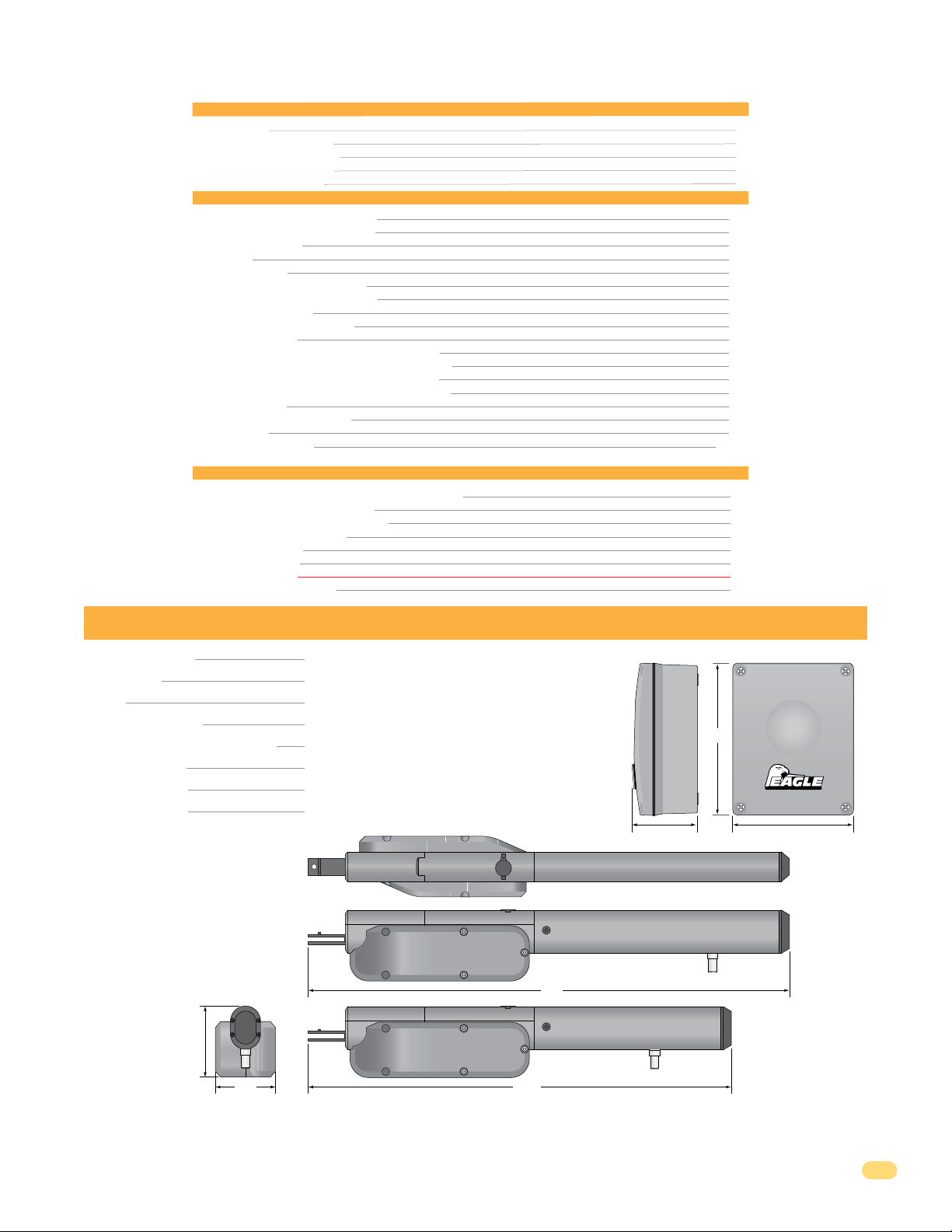
X9 SWING GATE OPERATOR SPECIFICATIONS
Control Box Power 115 VAC @ 60 Hz - 4 amps per Arm
Motor Power 24 VDC @ 180 Watts per Arm
Thrust 1900
Normal Gate Cycles Intensive
Traveling Distance (Drive Screw) X9S: 13 3/4” X9L: 19 5/8”
Max Gate Length X9S: 10 ft per Gate X9L: 16 ft Per Gate
Max Gate Weight X9S: 700 lbs per Gate X9L: 800 lbs per Gate
Opening Time 90° X9S: 20 sec X9L: 25 sec
Entrapment Protection:
Built-In ERD adjustable reversing sensor
Input for non-contact sensor
Input for contact sensor
24
24
24
25
26
26
27
27
28
Control Box
11”
BY EAGLE ACCESS CONTROL SYSTEMS, INC.
4 5/8” 8 3/4”
X9L - Long Arm
41”
5 1/2”
5”
X9S - Short Arm
35”
© 2018 Eagle Access Control Systems, Inc.
All rights reserved. No part of this manual may be reproduced in any means: graphics, electronics or mechanical. Including photocopying
t the expr
with
X9 Slide Rev - H
written permission of the
r. Materials components and
ifications are
t to change without notice.
1

SAFETY
UL 325 Listings
1. Install the gate operator only when:
a) The operator is appropriate for the construction of the gate and the usage class of the gate.
b) All openings of a horizontal slide gate are guarded or screened from the bottom of the gate to a minimum of 6 feet (1.83 m) above the
ground to prevent a 2-1/4 inch (57.2 mm) diameter sphere from passing through the openings anywhere in the gate, and in that portion
of the adjacent fence that the gate covers in the open position.
c) All exposed pinch points are eliminated or guarded, and
d) Guarding is supplied for exposed rollers.
2. The operator is intended for installation only on gates used for vehicles. Pedestrians must be supplied with a separate access opening. The
pedestrian access opening shall be designed to promote pedestrian usage. Locate the pedestrian gate such that persons will not come in
contact with the vehicular gate during the entire path of travel of the vehicular gate.
3. The gate must be installed in a location so that enough clearance is supplied between the gate and adjacent structures when opening and
closing to reduce the risk of entrapment. Swinging gates shall not open into public access areas.
4. The gate must be properly installed and work freely in both directions prior to the installation of the gate operator. Do not over-tighten the
operator clutch or pressure relief valve to compensate for a damaged gate.
5. For gate operators utilizing Type D protection:
a) The gate operator controls must be placed so that the user has full view of the gate area when the gate is not moving.
b) The placard provided marked in letters at least 1/4 in. (6.4-mm) high with the word “WARNING” and the following statement or the
equivalent: “Moving Gate Has the Potential of Inflicting Injury or Death – Do Not Start Gate Unless Path is Clear” shall be placed adjacent
to the controls,
c) An automatic closing device (such as a timer, loop sensor, or similar device) shall not be employed, and
d) No other activation device shall be connected.
6. Controls intended for user activation must be located at least six feet (6’) away from any moving part of the gate and where the user is
prevented from reaching over, under, around or through the gate to operate the controls. Outdoor or easily accessible controls shall have a
security feature to prevent unauthorized use.
7. The Stop and /or Reset button must be located in the line-of-sight of the gate. Activation of the reset control shall not cause the operator to
start.
UL 325 Listings
8. A minimum of two (2) WARNING SIGNS shall be installed, one on each side of the gate where easily visible.
9. For gate operators utilizing a non-contact sensor in accordance with Usage Class:
a) See instructions on the placement of non-contact sensors for each type of application,
b) Care shall be exercised to reduce the risk of nuisance tripping, such as when a vehicle trips the sensor while the gate is still moving,
and
c) One or more non-contact sensors shall be located where the risk of entrapment or obstruction exists, such as the perimeter reachable
by a moving gate or barrier.
10. For gate operators utilizing a contact sensor in accordance with Usage Class:
a) One or more contact sensors shall be located where the risk of entrapment or obstruction exists, such as at the leading edge, trailing
edge, and post-mounted both inside and outside of a vehicular horizontal slide gate.
b) One or more contact sensors shall be located at the bottom edge of a vehicular vertical lift gate.
c) One or more contact sensors shall be located at the pinch point of a vehicular vertical pivot gate.
d) A hardwired contact sensor shall be located and its wiring arranged so that the communication between the sensor and the gate
operator is not subjected to mechanical damage.
e) A wireless contact sensor such as one that transmits radio frequency (RF) signals to the gate operator for entrapment protection
functions shall be located where the transmission of the signals are not obstructed or impeded by building structures, natural
landscaping or similar obstruction. A wireless contact sensor shall function under the intended end-use conditions.
f) One or more contact sensors shall be located on the inside and outside leading edge of a swing gate.
Additionally, if the bottom edge of a swing gate is greater than 6 inches (152 mm) above the ground at any point in its arc of travel, one
or more contact sensors shall be located on the bottom edge.
g) One or more contact sensors shall be located at the bottom edge of a vertical barrier (arm).
2
X9 Swing Rev - H
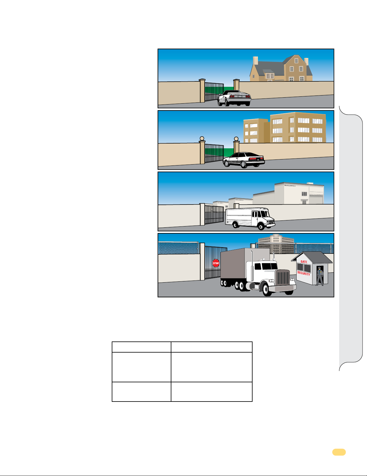
UL 325 Model Classifications
CLASS I
Residential Vehicular Gate Operator - A vehicular gate
operator (opener or system) intended for use in a home
of one to four single family dwellings, or a garage or
parking area associated therewith.
CLASS II
Commercial/General Access Vehicular Gate Operator - A
vehicular gate operator (opener or system) intended for
use in a commercial location or building such as a
multi-family housing unit (five or more single family
units) hotel, garages, retail store or other building
servicing the general public.
CLASS III
Industrial/Limited Access Vehicular Gate Operator - A
vehicular gate operator (opener or system) intended for
use in a industrial location, loading dock area or other
location not intended to service the general public.
CLASS I
CLASS II
UL 325 Classifi cations
CLASS III
CLASS IV
Restricted Access Vehicular Gate Operator - A vehicular
gate operator (opener or system) intended for use in a
guarded industrial location or buildings such as airport
security area or other restricted access locations not
servicing the general public, in which unauthorized
access is prevented via supervision by security
personnel.
CLASS IV
UL 325 Entrapment Protection
Entrapment Protection Requirements for Each Type of Operator.
Proper installation must satisfy the entrapment protection chart as shown.
Gate Type
Horizontal Slide
Vertical Lift
Vertical Pivot Gate
Swing Gate or
Vertical Barrier (arm)
A - Inherent (built into the gate operator) entrapment protection.
B1 - Non-contact sensor such as photo-eye or equivalent.
B2 - Contact sensor such as edge sensor or equivalent.
Entrapment Protection
A, B1*, B2* or D
A, B1*, B2* C or D
C - Inherent adjustable clutch or pressure relief device.
D - Actuating device requiring continuous pressure to
maintain gate motion.
* UL 325 requires that B1 and B2 means of entrapment protection must be MONITORED.
X9 Slide Rev - H
3
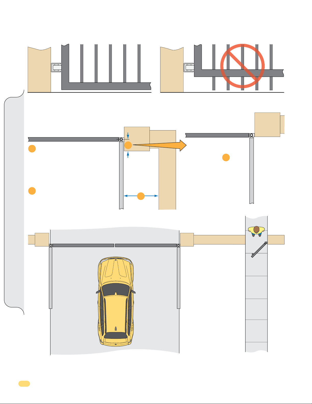
Swing Gate Recommendations
Gates should have smooth bottom edges, with vertical bottom edged protrusions not exceeding 0.50 inches.
Gate Closed
If distance is greater than 4 inches,
1
entrapment protection for this area
is recommended.
If distance is less than 16 inches,
2
entrapment protection in this area
is recommended.
Gates Closed
1
2
Gate Opened
Swing Gate Requirements
Gate Closed
With the hinge mounted on
the corner of the pilaster, the
entrapment area is
eliminated and protection is
NOT needed for this area.
1
Separate
Pedestrian
Access
Opening
Gate Opened
The operator is intended for installation ONLY on gates used for vehicles. Pedestrians should be supplied with a separate
access opening. The pedestrian access opening should be designed to promote pedestrian usage. Locate the gate such that
persons will not come in contact with the vehicular gate during the entire path of travel of the vehicular gate.
4
X9 Swing Rev - H
Important Safety Information
WARNING
To reduce the risk of injury or death read and follow the instructions
1. Never let children operate or play with gate controls. Keep the remote control away from children.
2. Always keep people and objects away from gate. NO ONE SHOULD CROSS THE PATH OF THE MOVING GATE.
3. Test the operator monthly. The gate MUST reverse on contact with a rigid object or stop when an object activates the non-contact
sensors. After adjusting the force or the limit of travel, retest the gate operator. Failure to adjust and retest the gate operator properly can
increase the risk of injury or death.
4. Use the emergency release ONLY when the gate is not moving and verify that operator power has been turned OFF.
5. KEEP GATES PROPERLY MAINTAINED. Read the owner's manual. Have a qualified service person make repairs to gate hardware.
6. The entrance is for vehicles only. Pedestrians must use separate entrance.
7. SAVE THESE INSTRUCTIONS.
General Safety Information
CAUTION
Be sure to read and follow all the Eagle Access Control Systems, Inc. and UL instructions before installing and
operating any Eagle Access Control System, Inc. products. Eagle Access Control Systems, Inc. is not responsible
for any improper installation procedures caused by failure to comply with local building codes.
General Safety
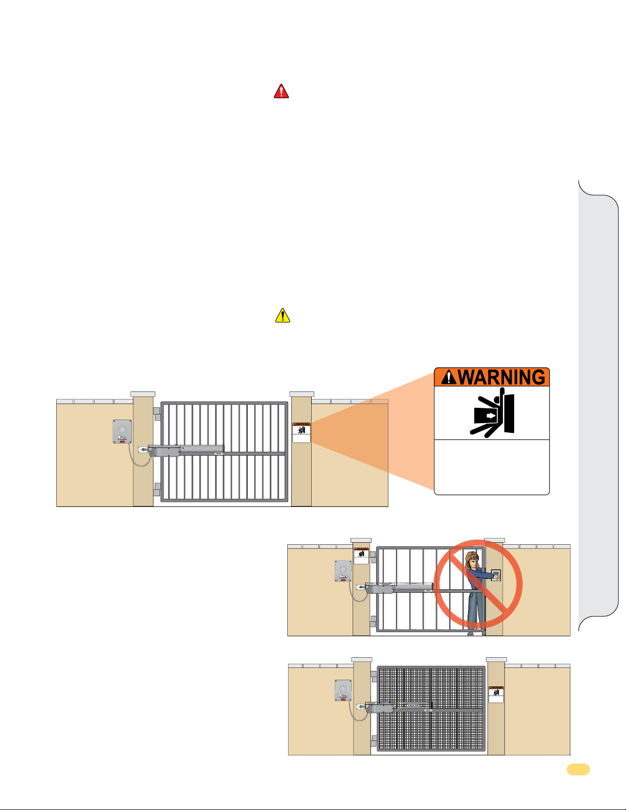
Install Warning Signs
BY EAGLE ACCESS CONTROL SYSTEMS, INC.
Install warning signs on BOTH sides of the gate.
Installing Opening Devices
Be sure to mount ALL gate operating devices at least six
feet (6’) away from any moving part of the gate. They must
NOT be able to be operated reaching through the gate.
Moving Gate Can Cause
Serious Injury or Death
KEEP CLEAR! Gate may move at any time
without prior warning.
Do not let children operate the gate or play
in the gate area.
This entrance is for vehicles only.
Pedestrians must use separate entrance.
BY EAGLE ACCESS CONTROL SYSTEMS, INC.
Moving Gate Can Cause
Serious Injury or Death
KEEP CLEAR! Gate may move at any time
without prior warning.
Do not let children operate the gate or play
in the gate area.
This entrance is for vehicles only.
Pedestrians must use separate entrance.
Moving Gate Can Cause
Serious Injury or Death
KEEP CLEAR! Gate may move at any time
without prior warning.
Do not let children operate the gate or play
in the gate area.
This entrance is for vehicles only.
Pedestrians must use separate entrance.
Ornamental Grill Styled Gates
Injuries may be avoided if a mesh screen is installed on
the gate. Injuries resulting from hands and feet becoming
stuck in the gate or children riding on the gate while gate
is moving can be greatly reduced if this “screen” or
“mesh” is applied to the gate as a safety precaution.
X9 Slide Rev - H
BY EAGLE ACCESS CONTROL SYSTEMS, INC.
Moving Gate Can Cause
Serious Injury or Death
KEEP CLEAR! Gate may move at any time
without prior warning.
Do not let children operate the gate or play
in the gate area.
This entrance is for vehicles only.
Pedestrians must use separate entrance.
5
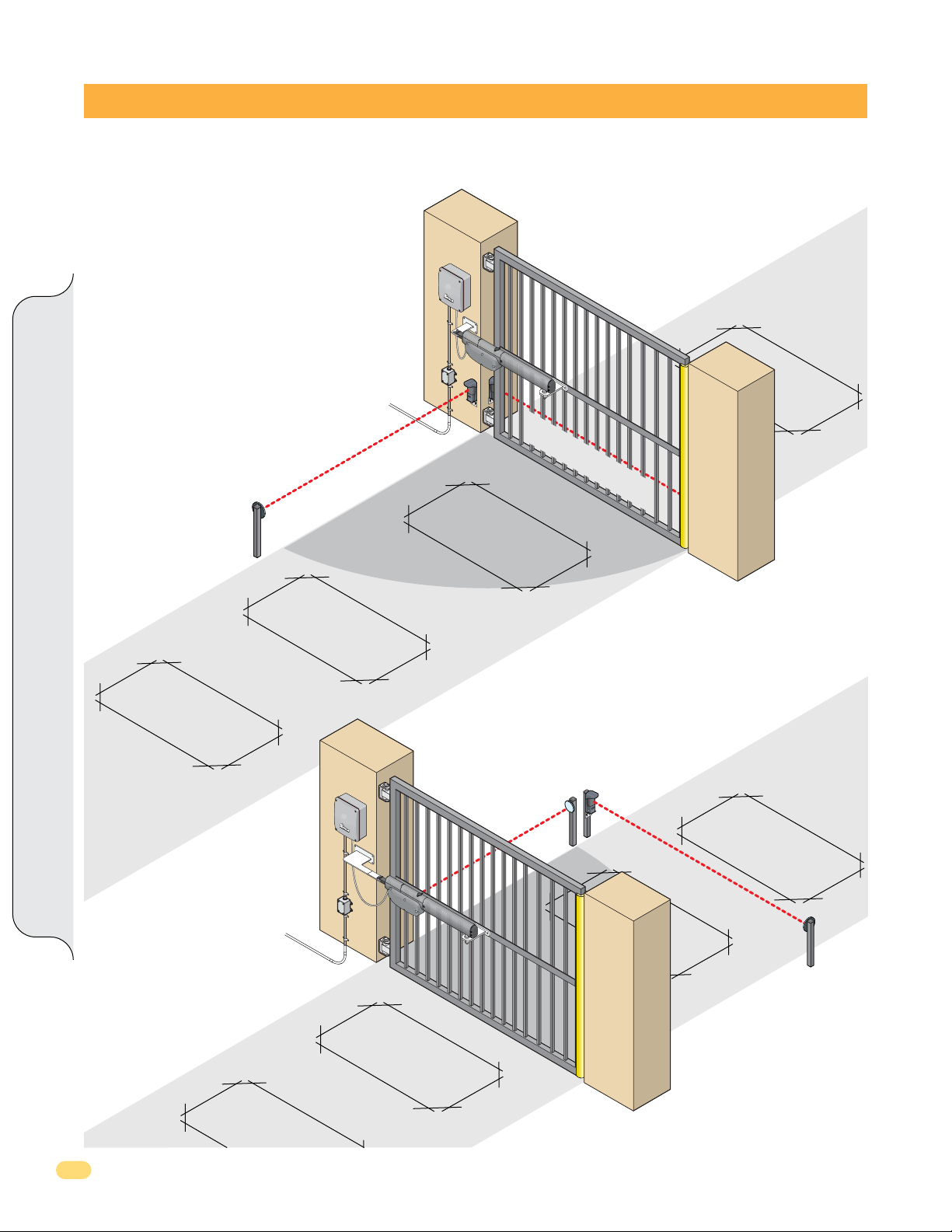
SAMPLE SINGLE GATE INSTALLATION SETUPS
An experienced installer should perform the installation. Improper installation may result in property damage, severe injury or death.
Read the entire manual before proceeding with the installation.
Eagle Access Control Systems, Inc. is not responsible for researching and complying with local building codes. Be sure to check all local
building codes before installation.
These drawings are typical and is supplied as working model
from which to choose the electronic components making up
the single gate installation. Dual gates setup is on the next
page. These drawings do not lay down any requirements
regarding the installation of the gate operator. Please see the
previous pages for safety and general gate recommendations.
Any external safety devices get wired to the control box in
conduit when possible.
B
Y
E
A
GL
E
A
C
C
E
S
S
C
O
NT
R
O
L
S
Y
S
T
E
M
S
,
I
N
C
.
Sensing Edge
Safety Loop
Closing-Direction Photocell
(Outside of Property
Opening-Direction Photocell
(Inside Property)
Phantom Loop
(Shadow)
OPEN INSIDE
Safety Loop
Exit
L
oop
Opening-Direction Photocell
B
Y
E
A
G
LE
A
C
C
E
S
S
C
O
N
T
R
O
L
S
Y
S
T
E
M
S
,
I
N
C
.
(Outside Property)
Single Gate Installation Setup
Sensing Edge
)
Closing-Direction Photocel
(Outside of Property
Phantom
Loop
(Sha
dow)
Safety Loop
l
)
Safety Loop
OPEN OUTSIDE
Exit
Loop
6
X9 Swing Rev - H
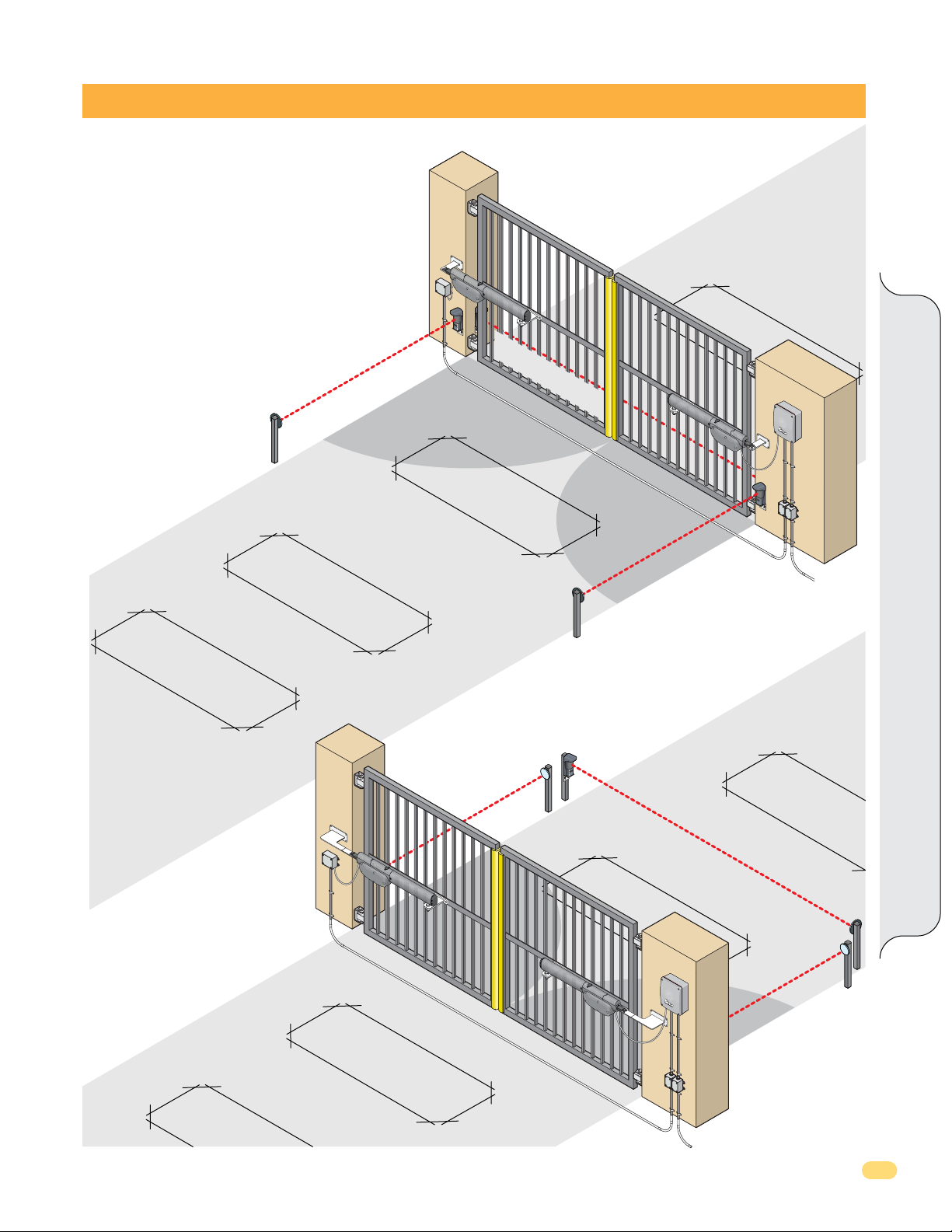
SAMPLE DUAL GATES INSTALLATION SETUPS
These drawings are typical and is supplied as working model from
which to choose the electronic components making up the dual
gates installation. These drawings do not lay down any requirements
regarding the installation of the gate operators. Please see the pages
2-5 for safety and general gate recommendations.
Any external safety devices get wired to the control box in conduit
when possible.
Opening-Direction Photocell
(Inside Property)
OPEN INSIDE
Closing-Direction Photocell
(Outside of Property)
Master / Slave Connection
Phantom Loop
(Shadow)
Sensing Edges
Safety Loop
l
Dual Gate Installation Setup
BY
E
A
G
L
E
A
C
C
E
S
S
C
O
N
T
R
O
L
S
Y
S
TE
M
S
,
I
NC
.
Exit Loop
Safety
Loop
Opening-Direction Photocell
(Outside Property)
Sensing Edge
Master / Slave Connection
rection Photocel
-Di
g
in
Open
Closing-Direction Photocell
Safety Loop
(Outside of Property)
s
Phantom Loop
(Shadow)
n
o
g-Directi
B
Y
E
AG
L
E
A
CCES
S
C
O
NT
R
O
L
S
Y
S
T
E
M
S
,
I
N
C
.
Openi
n
Photocell
X9 Slide Rev - H
OPEN OUTSIDE
Exit Loop
Safety Loop
7
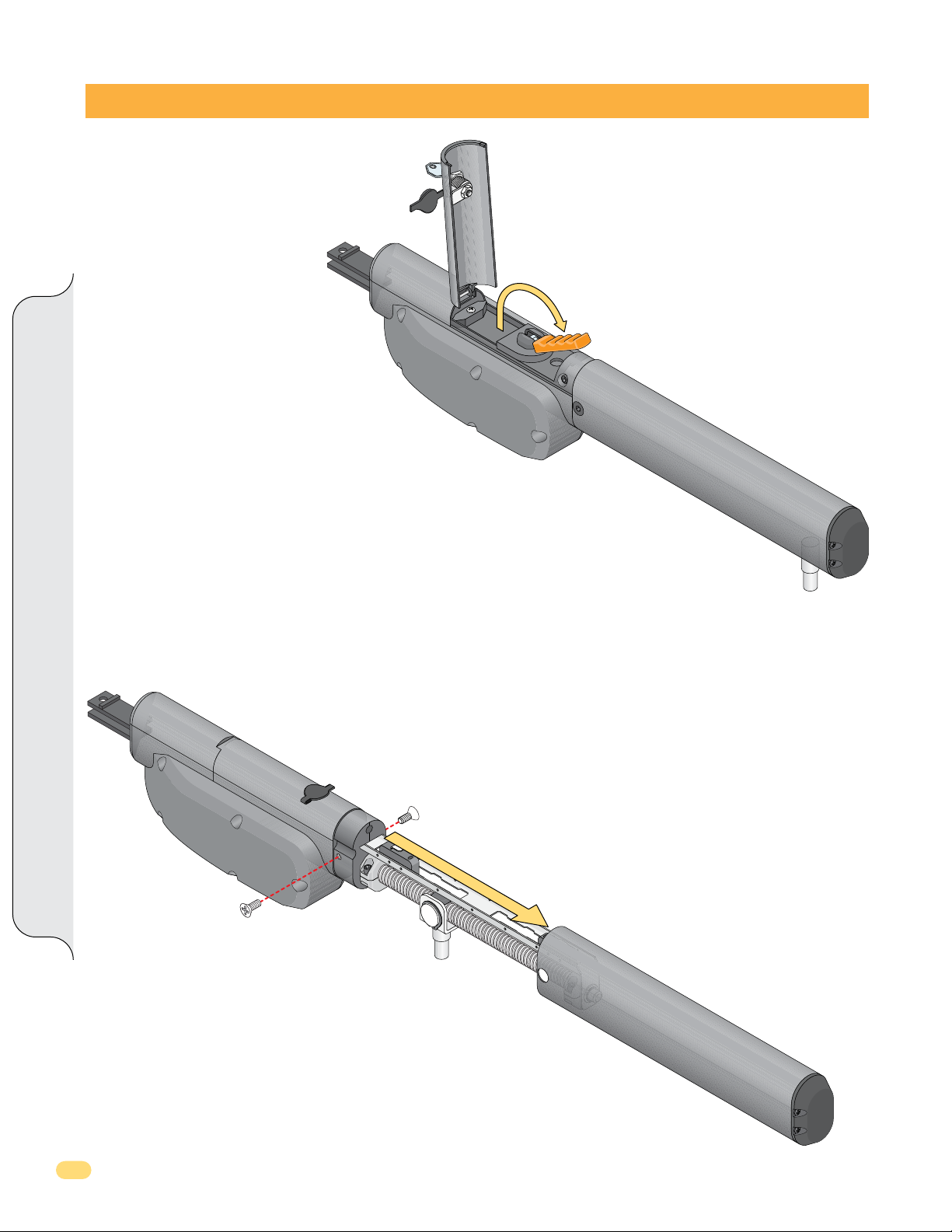
DISASSEMBLE OPERATOR
Step 1 - Release Stroke Pin
The stroke pin must be released before
installation.
1. Unlock with Key and open door.
2. Flip orange handle forward.
3. Stroke pin can now be moved.
NOTE: The stroke pin can REMAIN
UNLOCKED by simply removing
the orange handle in the released
position.
4. To Lock Stroke Pin again: Flip orange
handle back to original position.
5. Close and lock door.
Key
Door
Released Position (Unlocked)
Step 2 - Remove Cover to Access Limit Assembly
1. Remove two 5mm allen screws
2. Slide cover off.
Disassemble Operator
Stroke Pin
Cover
8
X9 Swing Rev - H
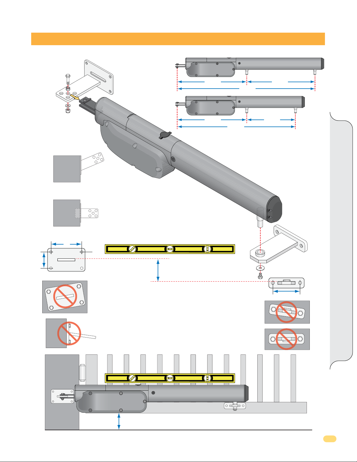
MOUNT ARM
Rear
Option
Weld Bracket at an Angle
Option
Cut Bracket to Fit
NOTE: Weld COMPLETELY around bracket.
X9L-Long Arm
18 3/4” 19 5/8”
X9S-Short Arm
18 3/4”
32 1/2”
Min Stroke
38 1/2”
Min Max
13 3/4”
NOTE: Release the stroke pin before installation,
see “Release Stroke Pin” on previous page.
Max Stroke
Stroke Pin
See pages 11 and 12 for
dimensional layouts.
Mount Arm
2”
4”
Rear Bracket
Not Level
Not Level
Arm MUST be Installed LEVEL!
2” Offset Between Brackets
COMMON MISTAKES
TO BE AWARE OF:
Front
Front Bracket
3 3/4”
Not Level
Upside Down
X9 Slide Rev - H
4” Minimum Above Ground
9
 Loading...