

Page 1
RA-1000
RESIDUAL ANALYZER
Installation and Operation
MANUAL
Page 2

TABLE OF CONTENT
I INTRODUCTION 3
II SPECIFICATIONS 3
III PRINCIPAL OF OPERATION 4
A GENERAL 4
B REAGENT FEED SYSTEM 4
IV INSTALLATION 5
A WALL PANEL MOUNTING 5
B HYDRAULIC CONNECTIONS 5
C TERMINAL CONNECTIONS 5 (DIAGRAM)
V REAGENTS 5
A LIQUID REAGENTS 6
BCARBON DIOXIDE 6
VI START-UP 7
VII OPERATION 7
A CLEANING 7
B REAGENT VALVE (STAR WHEEL) 8
C GOLD ELECTRODE 9
D MOTOR / STRICKER 10
E MOTOR REPLACEMENT 10
VII C02 BUFFERING 11
IX TROUBLE SHOOTING 11 - 13
X INSTRUMENT SETTINGS 13 - 18
XI WIRING DIAGRAM 19
2
Page 3

I. INTRODUCTION
The RA-1000 Residual Analyzer/Controller is an amperometric instrument
designed to continuously analyze residual levels of free or total chlorine, chlorine
dioxide, or potassium permanganate in water, wastewater or liquids containing
particulates.
II. SPECIFICATIONS
Power Supply 115/230 VAC Switch selectable.
Power Consumption 12W
Display LCD, backlit, 16 characters by 2 lines, 5mm character
height,5x8 character matrix.
Pushbuttons Four, tactile dome.
Relays High residual, low residual, and two spares
Mechanical (AC or DC), Rating (standard) 1.2A,
125VAC resistive or optional 5A @ 250VAC
Cell Au/Cu (Gold anode/Copper Cathode) Galvanic Cell
input
Temperature Thermistor 10kohms @ 25C, Beta=4100
Analog Output Isolated, 4 to 20mA, 500ohm drive. Represents CL
2
residual
Digital Output 20mA Serial (transmits to remote computer)
Instrument Range: 0-0.1, 0-0.2, 0-0.3, 0-0.5, 0-1, 0-2, 0-3, 0-5, 0-10, 0-20,
0-30 mg/l field selectable
Sample Flow: 500 cc/minute: 5 psig maximum
Sample Supply: Continuous. Where sample interruption may be required;
provisions must be made to keep the electrodes wet with
fresh water.
Analyzer Location: As close as possible to the sample point to reduce lag
time.
Speed of Response: 4 Seconds from sample entry to display indication. Full
scale residual change 1-1/2 to 2 minutes.
3
Page 4

Ambient Temperature 35 degrees to 120 degrees F (2 degrees to 50
Range: degrees C)
Sample Temperature 35 degrees 120 degrees F
Range: (2 degrees to 50 degrees C)
Sample Limitations: Samples containing high concentrations of metal ions or
certain corrosion inhibitors my effect analyzer operation.
Accuracy: +/- 2% of selected range
Electronics Enclosure: NEMA 4X
Reagent Requirements:
RESIDUAL MEASUREMENT REAGENT REQUIREMENTS
Chlorine (Free) pH buffer or CO
gas
2
Chlorine (Total) pH buffer or CO2 gas & potassium iodide
Chlorine Dioxide pH buffer & potassium iodide
Potassium Permanganate pH buffer
III. PRINCIPAL OF OPERATION
A. GENERAL
A sample of liquid is delivered to the sample filtering chamber at an
approximate rate of 500 cc/minute. The excess overflows to drain.
The sample then passes through the annular space between the two
fixed electrodes in the sensing cell. As it passes, a small direct current is
generated in direct linear proportion to the amount of chemical present in
the liquid.
The surface of both electrodes is kept clean by the continuous action of
PVC spheres agitated via a motor driven rotating striker.
This constant cleaning eliminates signal drift and recalibration providing an
accurate residual measurement. A thermistor compensates for sample
temperature variations.
The residual value is displayed on the LCD display.
B. REAGENT FEED SYSTEM
Reagents are fed into the sensing cell to lower the pH to enable reliable
measurement. The sample pH is adjusted by the buffer to a range of
4.0 to 4.5 pH. When CO2 is used as a buffer, the pH will be lowered to
a range of 5.5 to 6.0 pH. The addition of potassium iodide, when used,
reacts to liberate free iodine and provides a means of measurement of
total chlorine residual. Refer to CO2 BUFFERING on page 9 for CO
operation.
2
4
Page 5
IV. INSTALLATION
A. WALL PANEL MOUNTING
1. Position the analyzer panel on a wall at eye level and as close as
possible to the sample source. Secure with bolts, leveling the
analyzer before securing.
B. HYDRAULIC CONNECTIONS
1. Connect the necessary length of drain hose to the drain outlet
on the analyzer. Secure with a hose clamp. Route hose to
maintain a gravity fed drain (downward slope).
2. Connect one end of the 3/8” sample supply tubing to the source
using a suitable connection (customer supplied). Route tubing to
the sample filter chamber through the tubing holders on the
analyzer panel. Position the end of the tubing between the filter
0chamber and below the top of the overflow weir.
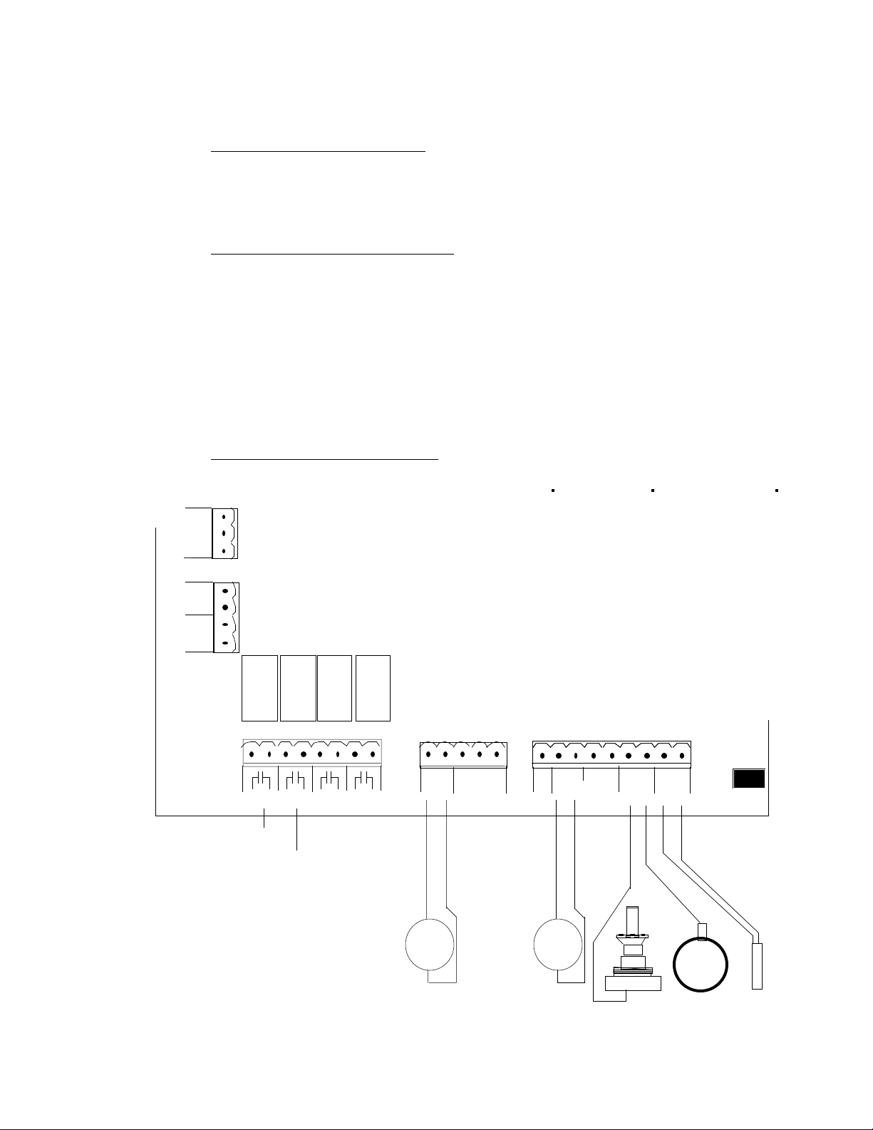
C. TERMINAL CONNECTIONS
TB5
G
1
POWER
AC
N
2
H
3
TB4
SW
motor
1
2
3
4
K1 K2 K3 K4
1
TB1
K1 K2 K3 K4
LOW
HIGH
RESIDUAL
RELAY
8234 567
1
TB2
+ -
4-20mA
P01
+
CONTROL
OUTPUT
-
COM
Tx
5
1 9
TB3
+ - + -+ - + -
+ -
+ -
Rx
12V
SCR
4-20mA
PV1
+ - + -
PV2
+
CONTROL
INPUT
-
A B
mV
CELL THRM
PASS
5
Page 6

NOTE: ALL WIRING MUST COMPLY WITH APPLICABLE
LOCAL AND NATIONAL ELECTRICAL CODES.
1. Remove four (4) screws securing side cover and remove cover.
2. Connect input power (120 Vac standard) to N,H,G terminals.
3. Connect current output and alarm contacts.
NOTE: DO NOT RUN LINE VOLTAGE AND SIGNAL VOLTAGE
IN THE SAME CONDUIT.
V. REAGENTS
A pH buffering solution or carbon dioxide gas is required for analyzer operation.
In addition, potassium iodide solution is required when measuring other residuals
as described in the SPECIFICATIONS Section.
Fill reagent bottle with pre-mixed solution or mix reagents as follows:
NOTE: NEVER DISABLE UNIT WITHOUT REMOVING REAGENT
BOTTLE AND FLUSHING WITH CLEAN WATER UNTIL THE ENTIRE
CHEMICAL IS REMOVED.
A. Liquid Reagents for Chlorine Residual
Pre-mixed pH buffer solution is available, contact factory. OR, mix pH
buffer solution as follows:
1. For Free Chlorine Measurement:
a. Using a 2 quart (1.9-liter) bottle, fill bottle 3/4 full with
distilled/deionized water.
b. Add 460 grams sodium acetate trihydrate crystals and mix until all
the crystals are dissolved.
c. Add 900 grams or 885 cc glacial acetic acid or distilled white
vinegar.
d. Fill bottle to the top with distilled or deionized water and shake to
thoroughly mix solution and pour contents into the analyzer
reagent bottle.
2. For Total Chlorine Measurement:
Mix potassium iodide solution in a separate bottle. (Potassium iodide
crystals are available. Contact factory.)
a. Follow Steps 1.a. through 1.d. above.
b. Add potassium iodide crystals as follows:
6
Page 7

ANALYZER RANGE
10 grams for 0.5 mg/l
40 grams for 2.0 mg/l
60 grams for 3.0 mg/l
100 grams for 5.0, 10, 20 and 30 mg/l
c. Shake until crystals are completely dissolved.
d. Fill bottle to the top with distilled/deionized water; shake again.
Pour contents into the reagent bottle through a fine strainer. The
bottle will provide approximately a one week supply of reagent.
B. Carbon Dioxide Gas
When using carbon dioxide for pH buffering, a carbon dioxide gas flow
rate of 200 cc per minute is required. For free chlorine measurement,
carbon dioxide is used alone, and replaces the liquid buffer . When
measuring total chlorine using carbon dioxide, it is necessary to add
potassium iodide solution in the quantities listed above, 2.b., to deionized water alone.
NOTE: For Chlorine Dioxide and Potassium Permanganate consult
factory.
VI. START-UP
A. Hold filled reagent bottle upright and pull the tapered plug upward until
the hole in cap is plugged. Turn bottle upside down and install into
reagent feeder body. The weight of the reagent bottle opens the
tapered plug and the bottle will rest on the o-ring on top of the feeder
body.
B. Start water sample flow at approximately 500 cc/minute . To drain, water
must be flowing over the overflow weir in the sample filter chamber.
The sample must be supplied continuously for reliable operation. If the
system requires occasional sample cutoff, provisions must be made to
keep the electrodes wet.
Sampling from a pressurized source may require a pressure regulating
valve to hold the flow constant. Maximum desired pressure: 5 psig (0.3
bar).
If sampling from sewage, a flushing “Y” strainer is necessary to prevent
sample line from plugging. Other types of filters are not recommended.
C. Turn the power on to the analyzer.
D. If air bubbles are present in the reagent or flow tubing, remove by
squeezing or tapping tubing or disconnecting tubing at the analyzer and
flushing momentarily.
7
Page 8

E. The analyzer requires a minimum stabilization time of 24 hours. During
this time, reagents must be feeding into the cell . Under normal
circumstances, reagent level will drop approximately 1" per 24 hrs.
C. After stabilization, calibration may be required. Instruments are calibrated
at the factory; at start-up Auto Zero adjustment is necessary to
compensate for composition of the local water.
III. OPERATION
C. CLEANING
The frequency of cleaning the analyzer is greatly affected by the condition
of the water. By visually inspecting for dirt built-up, determine the need
for cleaning. The following points should be cleaned as indicated:
1. The inlet filter screen and overflow weir should be cleaned when a
2. If the analyzer becomes clogged to the point where no water is
dirt build-up is observed or when the screen has been plugged
sufficiently to stop flow.
Lift out the overflow weir and filter screen. Hold parts under a
water stream until clean and reinstall in the analyzer.
passing over the overflow weir, the analyzer must be flushed.
The overflow can be observed below the motor or by the
overflow tube directly behind the cell for flow into the drain block.
Flush as follows:
a. Turn the power switch to the OFF position.
b. Remove the flush plug in the flow tube with sample
flowing and allow to drain.
c. Install flush plug into flow tube.
d. Repeat step b (steps b and c can be repeated until
the unit is clean).
e. Turn the power switch to the ON position and resume
operation.
B. REAGENT VALVE
If the reagent feed has stopped and all air is removed from tubing, the
reagent valve (P/N 450044) must be cleaned. The feed rate of this
valve is very small, therefore, be certain the reagent has stopped before
cleaning is attempted. Check for feed by marking the reagent level on
the bottle and observing the change in level over eight (8) hours. If the
reagent level has not lowered during this test, the valve must be cleaned.
Proceed as follows:
1. Turn the power switch to the OFF position.
8
Page 9

2. Stop sample flow.
3. Lift and rotate clip securing the reagent bottle. Raise
reagent bottle approximately 2” and pull down on the valve stem
until the hole in the cap is plugged. Remove reagent bottle.
4. Hold reagent bottle upright, unscrew and remove cap. Place
open bottle close to clear tubing connector at adaptor. Carefully
unscrew connector nut releasing clear tube and drain remaining
reagent from the reservoir into the reagent bottle. Screw cap onto
reagent bottle.
5. Remove flush plug to drain unit. After the analyzer is completely
drained, replace plug.
6. Loosen the four (4) screws securing the adaptor and remove
adaptor and o-ring.
7. Clean out bottom body if necessary.
8. The adaptor provides mounting for reagent valve components.
This valve consists of a starwheel, bushing, pin, o-ring, spring clip
and a screw. Loosen the screw and rotate the spring 180
degrees. Pull up on the starwheel to release the pin from
bushing. DO NOT remove bushing or o-ring. Clean all parts
under a stream of water. If the 1/16” diameter holes in the
starwheel and bushing are clogged, use a straight pin to remove
the obstruction. DO NOT scratch the mating surfaces or damage
the edge of the hole. Place starwheel and pin into bushing. Turn
the spring clip back 180 degrees to apply force to the pin.
Secure screw.
9. Place large o-ring into groove and replace adaptor. Secure, using
four (4) screws.
10. Reconnect clear tubing to connector and secure nut.
11. Invert reagent bottle on reservoir and secure using clip provided.
12. Begin sample flow as described under START-UP.
13. Turn power switch to the ON position. If air bubbles appear in
the clear reagent tubing, remove as described in START-UP.
C. GOLD ELECTRODE
Normal life of the gold electrode is three to five years. This can vary
depending upon chemical residual and the quality of water. The gold
electrode should appear clean and shiny.
NOTE: THE MEASURING CELL ASSEMBLY RETAINS 200 - 3/16”
DIAMETER PVC SPHERES WITHIN THE TOP BODY OF THE
9
Page 10

ANALYZER. WHEN THIS ASSEMBLY IS WITHDRAWN, THESE
SPHERES WILL DROP OUT.
1. Refer to OPERATION, Section B and proceed with Steps 1
through 7. Remove the adapter and all reagent.
2. Disconnect the wire from the gold electrode assembly.
3. While holding a bucket under the analyzer, unscrew the gold
electrode by hand. As the assembly is withdrawn, the spheres
will begin dropping out. Hold the bucket below until all the
spheres are removed. Remove large o-ring on the electrode
assembly.
4. Inspect the condition of the gold electrode. Clean and polish with
water and clean cloth. If electrode is damaged, replace.
5. Place large o-ring in groove on new electrode assembly and
screw the assembly into the bottom body, by hand, until snug.
6. Reconnect wire to the gold electrode assembly.
7. Remove the plug located in the analyzer top body. Deposit all
spheres through the hole provided and replace plug.
8. After spheres have been deposited, rotate motor/striker
assembly by hand, checking for rubbing. The striker can be
observed below the motor. If the striker is not rotating, refer
below to Section D, MOTOR/STRIKER ASSEMBLY. Turn
power switch to the ON position.
D. MOTOR/STRIKER ASSEMBLY
Replacing the motor (Part #450039) or striker assembly (Part #450045)
can be performed more easily if the main analyzer assembly is removed
from the panel and taken to a table or flat surface.
1. Disconnect power to the analyzer motor.
2. Disconnect signal wires from the copper and gold electrodes.
3. Remove reagent from the feeder body and reagent tubing from
valve adaptor. Unscrew two screws holding the main assembly
to the panel. Place the main assembly on a table.
4. With the main assembly upright, remove the three (3) screws
holding the motor plate to the top body. Lift the motor straight up
and out of the top body.
5. Invert the analyzer assembly and dump the 200 spheres into a
container. Remove the valve adaptor. The main assembly is
now disassembled as far as required.
10
Page 11

E. MOTOR REPLACEMENT
1. If the motor is to be replaced, remove the striker from the motor
shaft. Install on new motor after turning the center set screw out
approximately two (2) turns.
2. Turn the side set screw in striker until it contacts the motor shaft.
The striker should be capable of sliding onto the motor shaft when
force is applied.
3. Fit the striker on to the motor so a small space is between the top
of the striker and the motor plate. Insert motor/striker assembly
into the main analyzer assembly by pushing on the motor until the
motor plate is seated on the top body.
4. Carefully remove the motor/striker from the main assembly.
Lightly tighten the side set screw in the striker. Turn in center set
screw until contact is made with the motor shaft. Now, back out
center set screw 1/8 to 1/4 turn. Loosen side striker set screw and
push up on the motor shaft. Retighten side set screw snugly.
Reinstall the motor/striker assembly with the three (3) motor
screws.
5. Rotate the motor/striker assembly by hand checking for drag or
rubbing. The motor should turn freely by hand.
6. Insert the 200 PVC spheres and rotate motor/striker again, feeling
for drag or rough spots. If drag is present, repeat Steps 2
through 5 for adjusting the striker.
7. Reassemble to panel by reversing MOTOR/STRIKER
ASSEMBLY 1, 2 and 3.
VIII. CO2 BUFFERING
A. The CO2 diffuser replaces the pH4 buffer solution starwheel on the right
side of the analyzer. The CO2 diffuser may be placed on either side.
For total chlorine residual, the CO2 diffuser is placed on the left side of the
bottom body in place of the adaptor. Solution fed by the starwheel
assembly on the right side must be potassium iodide solution only.
B. Locate the vent tube over the analyzer drain.
C. Adjust regulator and rate valve to obtain a flow of about 0.25 ppd (44
ccm) of CO2 and check for gas leaks with soap solution. Check all tubing
connections at cylinder, regulator and analyzer and repair any leaks.
D. Set flow rate of CO2 initially at 1 ppd (175 ccm). The actual flow rate
may be adjusted. A constant pH should be maintained.
E. CO2 gas will buffer the sample water to maintain the pH level between 5
and 6. Calibration of the analyzer is unchanged.
CAUTION: Remember to turn off the CO2 cylinder anytime the
analyzer is shut down.
11
Page 12

IX. TROUBLESHOOTING CHART
NOTES:
A. Verify sample flow at the analyzer intake between the overflow weir and
the filter screen (500 cc/minute) )1 pint/minute) at 5 psig (0.3 bar). Verify
constant sample flow through the analyzer by observing flow at the
drains. SAMPLE MUST ALWAYS FLOW TO THE ANALYZER.
B. Verify analyzer motor connection to proper power supply and operating.
C. Verify reagent feed to the analyzer. Let the analyzer run for 24 hours and
measure reagent usage (normal 3/4” to 1-1/8” change in level).
TROUBLE: Excessively high or low output signal.
PROBABLE CAUSE: 1. Air bound sample or reagent line.
2. Dirty or worn electrode.
3. Damaged thermistor.
CORRECTIVE ACTION: 1. Check drain tubing for sample flow. For
inadequate flow from left drain, tap base of low
tubing to release trapped air bubbles.
2. See OPERATION, Section C. Remove, clean,
and/or replace gold electrode.
3, Test and replace thermistor. See
OPERATION, Section F.
TROUBLE: Output reacts slowly to residual change.
PROBABLE CAUSE: 1. Coating on measuring cell.
2. Excessive amounts of suspended solids.
3. Nonrepresentative sample.
CORRECTIVE ACTION: 1. Clean electrode.
2. Filter sample.
3. Relocate sample point.
TROUBLE: Motor operation noisy, erratic, no motion.
PROBABLE CAUSE: 1. Motor wired incorrectly.
2. Misaligned striker has PVC spheres jammed.
3. Faulty motor.
CORRECTIVE ACTION: 1. Rewire per label.
2. Adjust striker assembly. See OPERATION,
Section D. Check plug is tight in top body.
3. Replace motor. See OPERATION, Section G.
TROUBLE: Inadequate span adjustment.
PROBABLE CAUSE: 1. Coating on measuring cell.
3. Solids in measuring cell.
CORRECTIVE ACTION: 1. Clean electrode. See OPERATION, Section C.
2. Filter sample.
12
Page 13

TROUBLE: Inability to zero.
PROBABLE CAUSE: 1. Residual present in sample.
CORRECTIVE ACTION: 1. Use de-chlorinated water.
TROUBLE: Improper reagent feed.
PROBABLE CAUSE: 1. Faulty starwheel.
CORRECTIVE ACTION: 1. See OPERATION, Section B.
TROUBLE: Excessive reagent feed.
PROBABLE CAUSE: 1. Striker motor rotation reversed.
3. At shutdown, starwheel aligned for constant
reagent feed.
CORRECTIVE ACTION: 1. Motor must turn counterclockwise, (top view).
Inspect motor leads for proper connection.
2. Jog motor to reposition starwheel.
TROUBLE: Insufficient reagent feed.
PROBABLE CAUSE: 1. Starwheel plugged.
2. Blockage in feed line to the starwheel.
CORRECTIVE ACTION: 1. Clean. See OPERATION, Section B.
2. Check per OPERATION, Section B.
TROUBLE: Display blank.
PROBABLE CAUSE: 1. Power OFF.
2. Bad connector or incorrect wiring to control
unit.
CORRECTIVE ACTION: 1. Turn power switch ON or connect power.
2. Check for proper plug connections or repair /
replace LCD display module.
C. INSTRUMENT SETTINGS
The top line of the LCD display is formatted to show a selected value along with its
engineering units, and the second line normally provides function labels for the four pushbuttons
located below the display. The pushbuttons do not have any labels, so for the purpose of this
document, the pushbuttons will be assigned numbers 1 through 4.
Line1: Value & units
Line 2: Pushbutton legend
1 3 4
2
13
Page 14

MAIN RUN SCREEN
The value displayed is the chlorine residual in ppm or mg/l. Below the residual value is a fifty segment
bar-graph representation of the residual 4mA to 20mA output (PO1).
RES 5.00 ppm
[••••• ] SET
1
4 SET The user is prompted to enter a password to enter a programming mode in which
no label
Displays the water temperature.
one can calibrate, set alarm set-points, and set the 4-20mA output range.
PASSWORD ENTRY SCREEN
ENTER PASSWORD
0 0 0 ENT
RESIDUAL SETUP MENU
From the run screen, press SET and the user will be prompted to enter the password (default
is 000). If the entered password is correct, the residual setup (calibration, alarm, & range) menu will be
displayed.
RESIDUAL SETUP
CAL ALM RNG
RUN
1 CAL Enter calibration menu
2 ALM Set the high and low residual alarm setpoints
3 RNG Set the 4-20mA output range.
4 RUN Go back to the main run screen
CALIBRATE
CELL OUT
ESC
1 CELL Calibrate cell
2 No function
3 OUT Calibrate the 4-20mA output.
4 ESC First, the operator is prompted to enter a new password and then is returned to the
residual setup menu.
14
Page 15

CALIBRATE CELL
From the residual setup screen, press CELL to enter the cell calibration menu.
CALIBRATE CELL
ZRO SPAN
ESC
1 ZRO Zero cell input
2 SPAN Set the current CL2 residual.
3 no function
4 ESC Go back to the calibrate menu.
CALIBRATE ZERO SELECTION SCREEN
CALIBRATE ZERO
MAN AUTO
ESC
1MAN Manual zero
2 AUTO Auto zero
3 no function
4 ESC Go back to the calibrate cell menu.
MANUAL ZERO SCREEN
WAIT FOR...
0.0mV SET
ESC
The top line of the display scrolls the message, “ADD ZERO WATER & WAIT FOR STABLE mV.”
The left side of the bottom line shows the current cell mV.
1 No function
2 No function
3 SET Zero cell input.
4 ESC Go back to the calibrate zero menu.
15
Page 16

AUTO ZERO SCREEN
AUTO ZERO 120s
.. 0.0mV ESC
This screen will automatically zero the cell input if there is a stable mV input for 120 seconds. If the
auto zero successful, the instrument will display an auto zero successful message. If fifteen minutes
pass without an auto zero, the instrument will display an auto zero failure message.
The top, right side of the display shows a timer, and the bottom, left side shows the current cell mV.
1 No function
2 No function
3 No function
4 ESC Go back to the calibrate zero menu.
CALIBRATE CELL SPAN SCREEN
GET SAMPLE
0.0mV STR
ESC
1 No function
2 No function
3 STR Sample the cell input mV & water temperature and enter the screen where the CL
residual value can be set.
4 ESC Go back to the calibrate cell menu.
If one attempts to set a ppm when the mV input is lower than the zeroed mV, the error message
“ERROR! CELL mV <= ZERO” will be displayed for a few seconds.
2
16
Page 17

0.00ppm
UP DWN SET
ESC
1UPIncrease CL2 value
2DWN Decrease CL2 value
3 SET The value entered is the CL2 residual at the time the STR pushbutton was pressed.
4 ESC Go back to the get sample screen
CALIBRATING THE ANALOG OUTPUT
For one to calibrate the analog output, an accurate DMM or equivalent current meter (20mA
range) must be connected alone or in series with the 4 to 20mA (PO1) load.
SET ANALOG OUT
4mA 20mA
EXIT
14mA Set 4mA point
2 20mA Set 20mA point
3 No function
4 EXIT Go back to the calibrate menu.
SET XX.00mA OUT
UP DWN
SET
The XX.00 is either 4.00 or 20.00 and does not change when setting the selected point.
Observe the current reading from the DMM and use the up and down pushbuttons to set the
selected point to 4/20mA.
1UPIncrease current
2DWN Decrease current
3 No function
4 SET Store new 4mA or 20mA point
17
Page 18

SETPOINTS
The RA-1000 has CL2 residual high and low relay (alarm) outputs. Press ALM from the
RESIDUAL SETUP screen. Select either the LOW or HIGH set point. Use the up & down
pushbuttons to set the trip point and press set to store the new value. To disable a set point, enter a
zero value. A low set point is activated when the CL2 residual falls to or below the set point and is
deactivated when the CL2 residual rises above the trip set point plus a 0.10 (0.010) ppm(mg/l)
hysteresis. A high set point is activated when the CL2 residual rises to and above the high trip point
and is deactivated when the CL2 residual falls below the set point minus a 0.10 (0.010) ppm(mg/l)
hysteresis.
When an alarm occurs, a message appears in the main run screen indicating the exact alarm. One
now has two options:
IGNORE the alarm and de-energize the associated relay indefinitely.
CANCEL the alarm and de-energize the associated relay for 10 seconds and then reactivate the
alarm is the situation has not been resolved.
LOW 2.00 ppm
UP DWN
SET
HIGH 10.00 ppm
UP DWN
SET
CELL RANGE
To set the range, press RNG in the residual setup screen. There are two ranges set by S2 which is
located on the RA-1000 MAIN board.
RNG 0-10.00 ppm
UP DWN
SET
RNG
Value X.XX A 0 to 1,2,3,5,10, and 20 value selections (use the up and down pushbuttons
Value X.XXX B 0 to 0.1, 0.2, 0.3, 0.5, 1, and 2 value selections (use the up and down
S2
POSITION
Scales the 4-20mA analog output
to select)
pushbuttons to select)
18
Page 19

PASS
2
13
TB5
NGH
AC
POWER
TB4
2SW134
motor
9
THRM
A B
mV
CELL
+ -
+ -
PV2
+ -
+ -
+ -
+ -
4-20mA
PV1
+ -
+ -
12V
SCR
1
TB3
5
Rx
Tx
COM
P01
+ -
4-20mA
1
TB2
8
K4
7
6
K3
5
4
K2
3
2
K1
1
TB1
K4
K3
K2
K1
LOW
RELAY
HIGH
RESIDUAL
+
+
-
INPUT
CONTROL
-
OUTPUT
CONTROL
EAGLE MICROSYSTEMS
INH PN:
SCALE:
MATERIAL
RA-1000 WIRING
CIRCLE of PROGRESS POTTSTOWN, PA 19464
DATE:
DRWN:
TOLERANCE
FRACTIONS = ± 1/64
.X = ± .015
.XX = ± .010
.XXX = ± .005
.XXXX = ± .0005
LOW
RESIDUAL
K1
LOAD
H
HIGH
RESIDUAL
K2
LOAD
OPTIONAL
OPTIONAL
K3
K4
LOAD
N
LOAD
19
 Loading...