

Page 1

MICROPHONE 1 & 2 (P650A): These are unbalanced inputs using 2 pole standard 6.35mm
jack sockets located on the front panel. The levels are set by the respective controls adjacent
to the socket.
AUX/PHONO INPUT: Unbalanced inputs using standard RCA phono sockets are located on
the rear panel. The volume level is adjusted by the control located on the front panel.
These inputs can be used for PHONO and AUX sources (Tuner,Tape, CD) and should be
selected using the AUX/PHONO selector switch located on the rear panel.
Fig. 1: Wiring of signal plugs
Sleeve SleeveTip Tip
STANDARD 2-POLE 6.35mm JACK
Sleeve: Screen
Tip: Signal
Sleeve: Screen
Tip: Signal
RCA PHONO PLUG
MICROPHONE 1 (P650B): MIC 1 is an unbalanced input using a 2 pole standard 6.35mm
jack socket located on the rear panel. The volume level of the input is adjusted by the control
located on the front panel. MIC 1 has PRIORITY over all other inputs when the terminals
are short circuited.
PRIORITY COM 4Ω 8Ω 16Ω 100V
Fig. 2: Priority control
MICROPHONE 2 (P650B): MIC 2 is an unbalanced input using a 2 pole standard 6.35mm
jack socket located on the rear panel and the volume level is adjusted by the control located
on the front panel.
LOUDSPEAKER OUTPUT: Important:Outputs for two different types of loudspeakers are
provided, however you may only use one type at any one time, e.g. if you are using 100V
line loudspeakers you must NOT use low impedance outputs. DAMAGE to the amplifier will
be caused if this is not observed.
LOW IMPEDANCE: A low impedance 4Ω,8Ω,16Ω terminal is provided for connection of
loudspeakers. Ensure the total speaker load impedance is connected to the correct output
terminals, i.e. COM 4Ω,8Ω or 16Ω.
COM 4Ω 8Ω 16Ω 100V
8Ω 8Ω
Total impedance 4Ω
COM 4Ω 8Ω 16Ω 100V
16Ω 16Ω
Total impedance 8Ω
COM 4Ω 8Ω 16Ω 100V
8Ω
8Ω
Total impedance 16Ω
Fig. 3: Loudspeaker wiring
mix low impedance and 100V line loudspeakers on the same amplifier.
run microphone cables near mains, data, telephone or 100V line cables.
If you must cross these cables do it at 90°.
run 100V line cables near data, telephone or other low voltage cables.
exceed 90% of the amplifiers output power when using 100V line
(speech only).
exceed 70% of the amplifiers output power when using 100V line (high level
background music).
use re-entrant horn loudspeakers for background music unless the
loudspeaker has been specifically designed for this purpose.
low impedance loudspeakers if you are using more than two loudspeakers
and/or have long loudspeaker cable runs.
jointing the microphone cable, when this is unavoidable make sure a good
screened connector is used, e.g. XLR.
use a good quality microphone cable when extending.
use a mains grade double insulated cable for loudspeaker cable runs.
tha
t all loudspeakers are in-phase.
that there are no short circuits on the loudspeaker line before connecting to
the amplifier.
ENSURE
ENSURE
ALWAYS
ALWAYS
AVOID
AVOID
DO NOT
DO NOT
DO NOT
DO NOT
DO NOT
DO NOT
As the colours of the wires in the mains lead of this apparatus may not correspond with the
c
oloured markings identifying the terminals in your plug proceed as follows:
T
he wire which is coloured
g
reen and yellowmust be connected to the terminal which is marked
b
y the letter
‘E’o
r by the safety earth symbolor coloured green and yellow.
T
he wire which his coloured bluemust be connected to the terminal which is marked with the
l
etter
‘N’o
r coloured black.
T
he wire which is coloured brownmust be connected to the terminal which is marked with the
l
etter
‘L’o
r coloured red.
I
f a 13 Amp (B.S. 1363) plug or any other type of plug is used, a 5 Amp fuse must be fitted either
i
n the plug or at the distribution board.
P650A/P650B Installation and Operating Instructions
W
ARNING: THIS APPLIANCE MUST BE EARTHED
I
MPORTANTThe wires in the mains lead are coloured in accordance with the following code:
G
reen and Yellow: Earth (E)
B
lue: Neutral (N)
B
rown: Live (L)
1
Page 2

MIN MAX MIN MAX MIN MAX – 10 + 10 – 10 + 10 – 10 + 10
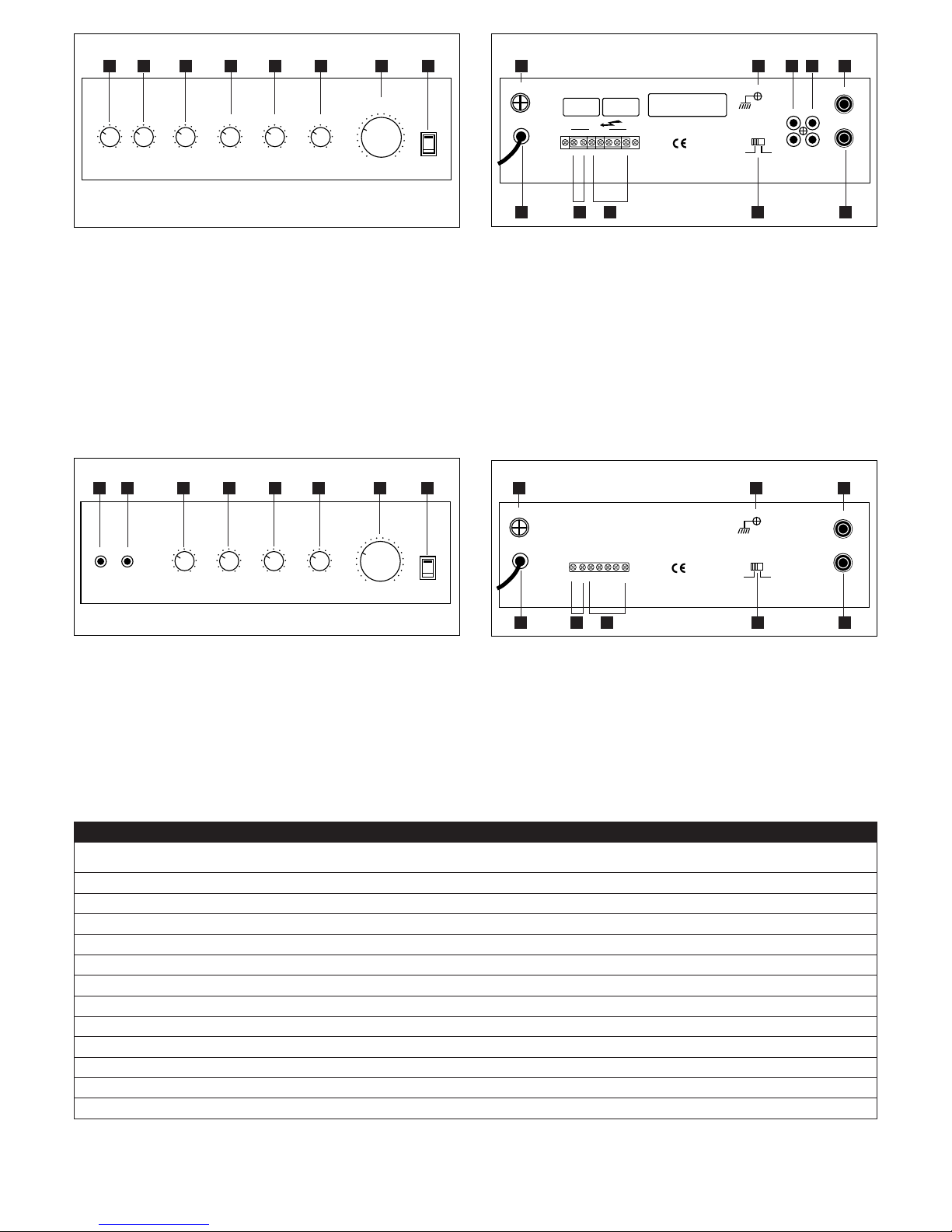
MASTER VOLUME
POWER
I
O
1kHz
0
6kHz
0
150H
0
FREQUENCY EQUALIZER
Fig. 4: Front panel P650B
POWER
I
O
Fig. 6: Front panel P650A
AUX PHONO
AUX PHONO
MIC 1
MIC 2L
R
GND
CAUTION:
T
O REDUCE THE RISK OF FIRE
REPLACE ONLY WITH THE SAME TYPE
AC FUSE
PRIORITY
COM 4Ω 8Ω 16Ω100V
OUTPUT
A
C FUSE
TO80A
L
INE 220V-240V
5
0Hz
Fig. 5: Rear panel P650B
PHONO AUX
AUX/CD
PHONO
G
ND
AC FUSE
T
O80A
LINE 220V-240V
50Hz
D
C 12V
–
+
C
OM 4Ω 8Ω 16Ω 100V
Fig. 7: Rear panel P650A
1 Mains power on/off switch
2 Master volume control
3 6kHz tone control
4 1kHz tone control
5 150Hz tone control
6 Phono/Aux level control
7 Mic 2 level control
8
Mic 1 level control
09 AC fuse holder
10 AC power cord
11 Priority terminal
12 Loudspeaker connector
13 Phono/Aux selector switch
14 Mic 2 input socket
15 Mic 1 input socket
1
6 Phono input socket (RCA)
17 Aux input socket (RCA)
18 Ground terminal
1 Mains power on/off switch
2 Master volume control
3 Tone control
4 Phono/Aux level control
5 Mic 2 level control
6 Mic 1 level control
7 Mic 2 input socket
8 Mic 1 input socket
09 AC fuseholder
10 AC power cord
11 DC power cord
12 Loudspeaker connector
13 Phono/Aux selector s
witch
14 Ground terminal
15 Phono input socket (RCA)
16 Aux/CD input socket (RCA)
P650A
P650B
Power output (RMS)
15W
30W
AC power 240V 50Hz 240V 50Hz
DC power 12V N/A
THD @ rated output
< 1%
< 1%
Frequency response ±3dB 100Hz - 13kHz 100Hz - 18kHz
Sensitivity: Mics –48 ± 2dB –55 ± 2dB
Aux
–12
±
2dB
–20
± 2dB
Phono N/A –55 ± 2dB
Signal to noise ratio: Mics
> 55dB > 55dB
Tone control ± 10dB ± 10dB
Weight 3.46kg 4kg
Dims (W x D x H) 320 x 230 x 83mm 320 x 230 x 83mm
SPECIFICATIONS
8 7 6 5 4 3 2 1 9
11 12 13 1410
1817161
5
6 5 4 3 2 1 9
10 11 12
1
4
13
1
6
15
8 7
2
Page 3

MICROPHONE 1 & 2 (P650A): Ces entrées jack 6.35 mm sont de type asymétrique et sont
situées en façade. Le niveau est contrôlé par les boutons adjacents.
ENTREES AUX / PHONO: Ces entrées asymétriques de type RCA sont situées à l’arrière de
l’appareil. Le contrôle de volume s’effectue par le bouton situé sur la façade avant. Ces
entrées peuvent être utilisées pour un Phono ou une source auxiliaire ( Tuner,Cassette, CD )
et la sélection s’opère grâce au commutateur situé à l’arrière.
Fig. 1: Câblage des entrées
Sleeve SleeveTip Tip
Fiche jack 6.35 mm standard
Sleeve : Masse
Tip : Point chaud
Sleeve : Masse
Tip : Point chaud
Fiche RCA
MICROPHONE 1 (P650B): L’entrée MIC 1 est une entrée asymétrique prévue pour un jack
standard de 6.35 mm située à l’arrière de l’appareil. Le contrôle de volume s’effectue sur la
face avant. MIC 1 est prioritaire sur toutes les autres entrées.
PRIORITY COM 4Ω 8Ω 16Ω 100V
Fig. 2: Contrôle de la priorité
MICROPHONE 2 (P650B): L’entrée MIC 2 est une entrée asymétrique prévue pour un jack
standard de 6.35 mm située à l’arrière de l’appareil. Le contrôle de volume s’effectue sur la
face avant
SORTIE HP : IMPORTANT: Des sorties pour 2 types de HP sont prévues mais vous ne pouvez
en utiliser qu’une seule. Par exemple, si vous utilisez une ligne 100 V, vous ne devez pas
utiliser les sorties à basse impédance. Si vous ne respectez pas cette consigne, vous risquez
d’endommager votre amplificateur.
BASSE IMPEDANCE: Une sortie basse impédance 4 Ohm, 8 Ohm,16 Ohm est prévue pour
le raccordement des haut-parleurs. Assurez vous que l’impédance totale des haut-parleurs
soit conforme à la sortie que vous utilisez ( COM 4 Ohm, 8 Ohm ou 16 OHM )
COM 4Ω 8Ω 16Ω 100V
8Ω 8Ω
Total impedance 4Ω
COM 4Ω 8Ω 16Ω 100V
16Ω 16Ω
Total impedance 8Ω
COM 4Ω 8Ω 16Ω 100V
8Ω
8Ω
Total impedance 16Ω
Fig. 3: Raccordement des haut-parleurs
Ne pas utiliser la sortie basse impédance et la ligne 100V en même temps.
Ne pas installer les câbles de liaison micro le long des lignes de téléphone
ou informatiques, si vous ne pouvez pas faire autrement faire le croisement à 90°.
Ne pas dépasser les 90% de la puissance maximale en charge autorisée
en ligne 100V (en version parole).
Ne pas dépasser les 70% de la puissance maximale en charge autorisée
en ligne 100V (en version musique d’ambiance).
Ne pas utiliser les haut parleurs à compression pour la musique
d’ambiance, sauf s’ils ont été conçus pour cette application (Bonne bande passante).
D’ utiliser les haut parleurs basse impédance lorsque vous devez installer
plus de deux haut parleurs, ou lorsque la liaison avec l’amplificateur est distante.
De mélanger les câbles des microphones surtout s’ils n’ont pas un bon
blindage.
Utiliser du très bon câble microphone pour vos rallonges.
Utiliser du câble à double isolation pour la connexion avec les haut
parleurs.
Que les haut parleurs sont bien câblés en phase.
Que les connexion des haut parleurs ne sont pas en court-circuit avant de
faire le branchement à votre amplificateur.
S’ASSURER
S’ASSURER
TOUJOURS
TOUJOURS
EVITER
EVITER
ATTENTION
ATTENTION
ATTENTION
ATTENTION
ATTENTION
Si les couleurs du câble d’alimentation secteur ne correspondent pas au marquage de votre prise,
v
euillez suivre les indications suivantes:
L
e câble
j
aune/vertdoit être connecté sur le contact marqué ‘E’ou sur le symbole de la terre ou
d
e couleur
j
aune/vert.
L
e câble bleudoit être connecté sur le contact marqué ‘N’ou de couleur noire.
L
e câble marrondoit être connecté sur le contact marqué ‘L’ou de couleur rouge.
P650A/P650B NOTICE D’UTILISATION ET D’INSTALLATION
A
TTENTION / CE MATERIEL DOIT ETRE RELIE A LA TERRE
I
MPORTANTLes fils doivent être connectés avec les codes suivants:
V
ert/jaune: Terre (E)
B
leu: Neutre (N)
M
arron: Phase (L)
Impédance totale 4 Ohm
Impédance totale 8 Ohm
Impédance totale 16 Ohm
3
Page 4

MIN MAX MIN MAX MIN MAX – 10 + 10 – 10 + 10 – 10 + 10
MASTER VOLUME
POWER
I
O
1kHz
0
6kHz
0
150H
0
FREQUENCY EQUALIZER
Fig. 4: Face avant P650B
POWER
I
O
Fig. 6: Face avant P650A
AUX PHONO
AUX PHONO
MIC 1
MIC 2L
R
GND
CAUTION:
T
O REDUCE THE RISK OF FIRE
REPLACE ONLY WITH THE SAME TYPE
AC FUSE
PRIORITY
COM 4Ω 8Ω 16Ω100V
OUTPUT
A
C FUSE
TO80A
L
INE 220V-240V
5
0Hz
Fig. 5: Face arrière P650B
PHONO AUX
AUX/CD
PHONO
G
ND
AC FUSE
T
O80A
LINE 220V-240V
50Hz
D
C 12V
–
+
C
OM 4Ω 8Ω 16Ω 100V
Fig. 7: Face arrière P650A
1 Bouton marche/arrêt
2 Contrôle de volume
3 Contrôle de tonalité 6 Khz
4 Contrôle de tonalité 1 Khz
5 Contrôle de tonalité 150 hz
6 Contrôle de niveaux PHONO/AUX.
7 Contrôle de niveaux MICRO 2
8
Contrôle de niveaux MICRO 1
09 Support de fusible
10 Cordon d’alimentation
11 Sortie prioritaire
12 Sorties H.P.
13 Sélecteur PHONO/AUX
14 Entrée MICRO 2
15 Entrée MICRO 1
1
6 Entrée PHONO/RCA
17 Entrée AUX/RCA
18 Prise de terre
1 Bouton marche/arrêt
2 Contrôle de volume
3 Contrôle de tonalité
4 Contrôle de niveaux PHONO/AUX
5 Contrôle de niveaux MICRO 2
6 Contrôle de niveaux MICRO 1
7 Entrée Mic 2
8 Entrée Mic 1
09 Support de fusible
10 Cordon d’alimentation
11 Alimentation
12 Sorties HP
13 Sélecteur PHONO/AUX
14 Prise de terre
15 Entrée PHONO (RCA)
16 Entrée Aux / CD (RCA)
P650A
P650B
Puissance RMS 15W 30W
Alimentation
240V 50Hz 240V 50Hz
Alimentation 12V N/A
Taux de distorsion < 1% < 1%
Bande passante ±3dB 100Hz - 13kHz 100Hz - 18kHz
Sensibilité:
Micr
os
–48
±
2dB
–55
± 2dB
Aux –12 ± 2dB –20 ± 2dB
Phono N/A –55 ± 2dB
Rappor
t signal br
uit:
Micros > 55dB > 55dB
Tonalité ± 10dB ± 10dB
Poids 3.46kg 4kg
Dimensions 320 x 230 x 83mm 320 x 230 x 83mm
CARACTERISTIQUES
8 7 6 5 4 3 2 1 9
11 12 13 1410
1817161
5
6 5 4 3 2 1 9
10 11 12
1
4
13
1
6
15
8 7
4
Page 5

Mikrofon 1 & 2 (P650A): Das sind 2 Eingänge mit 6,35mm Mono Klinkenbuchse an der
Frontseite.
AUX/PHONO INPUT: Eingang mit Cinch Buchse,Anschluß auf der Rückseite. Der Regler ist
auf der Frontseite angebracht. Diese Eingänge können für Phono und AUX Geräte
(TUNER, CD,TAPE) benutzt werden.
Fig. 1: Anschluß der Signalleitung
Sleeve SleeveTip Tip
MONO 6,35mm Klinkenstecker
Sleeve: Abschiermung
Tip: Signal
Sleeve: Abschiermung
Tip: Signal
Cinch Stecker
Mikrofon 1 (P650B): Mikro 1 ist ein Eingang mit Mono 6,35mm Klinkenbuchse an der
Rückseite des Gerätes. Der Lautstärkeregler ist auf der Frontseite angebracht. Mikro 1 hat
eine VORRANGSCHALTUNG.
PRIORITY COM 4Ω 8Ω 16Ω 100V
Fig. 2: Vorrangschaltung
Vorranganschluß COM
Mikrofon 2 (P650B): MIC 2 ist ein Eingang mit Mono 6,35mm Klinkenbuchse an der
Rückseite des Gerätes. Der Lautstärkeregler ist auf der Frontseite angebracht.
Lautsprecherausgang: WICHTIG !!! Es dürfen entweder niederohmige Lautsprecher oder
100 Volt Lautsprecher gleichzeitig angeschlossen werden. Falls Sie 100 Volt Lautsprecher an
den Verstärker angeschlossen haben,DÜRFEN Sie nicht niederohmige Lautsprecher
anschließen. Falls Sie das nicht beachten, wird der Verstärker beschädigt werden.
Niederohmige Anschlußleiste: Eine Lautsprecheranschlußleiste mit Steckplätzen für
4(, 8( und 16( befindet sich auf der Rückseite des Gerätes. Bitte beachten Sie die
Gesamtimpendanz der Lautsprecher und schließen Sie diese wie folgt an.
COM 4Ω 8Ω 16Ω 100V
8Ω 8Ω
Total impedance 4Ω
COM 4Ω 8Ω 16Ω 100V
16Ω 16Ω
Total impedance 8Ω
COM 4Ω 8Ω 16Ω 100V
8Ω
8Ω
Total impedance 16Ω
Fig. 3: Lautsprecheranschluß
100V Lautsprecher mit niederohmigen Lautsprecher an einem
Gerät.
Mikrofonkabel in der Nähe von Daten-, Netz-, Telefon- oder 100V
Kabel. Falls sich Kabel kreuzen müssen, verlegen Sie dieses im 90° Winkel
100V Kabel in der Nähe von Da
ten-, Netz- oder Telefonkabel.
Sie den Verstärker NICHT mehr als mit 70% der angegebenen
Verstärkerleistung.
Sie den Einsatz vom mehr als 2 Stück niederohmigen
Lautsprechern oder lange Verbindungskabel.
Sie lockeres Mikrofonkabel, benutzen Sie gute Verbindungen
z.B.: XLR.
Sie IMMER qualitative gutes Mikrofonkabel, falls Sie es
verlängern müssen.
Sie IMMER ein doppeltes isoliertes Lautsprecherkabel.
Sie sich, daß alle Lautsprecher in Phase geschaltet werden.
Sie sich, daß die Lautsprecher keine Kurzschlüsse verursachen.
VERGEWISSERN
VERGEWISSERN
Benutzen
Benutzen
VERMEIDEN
VERMEIDEN
Belasten
Verlegen Sie NICHT
Verlegen Sie NICHT
Verbinden Sie NICHT
Falls die Farben in Ihrer Netzleitung nicht mit dieser Beschreibung übereinstimmen sollten
v
erfahren Sie bitte folgendermaßen:
D
ie
G
RÜN/GELBELeitung muß an die Klemme mit dem Erdungssymbol oder mit dem Buchstaben
‘E’a
ngeschlossen werden
.
D
ie BLAUELeitung muß an die SCHWARZEoder mit dem Buchstaben ‘N’ gekennzeichnete
K
lemme angeschlossen werden
D
ie
B
RAUNELeitung muß an die ROTEoder mit dem Buchstaben ‘L’ gekennzeichnete Klemme
a
ngeschlossen werden
.
P650A/P650B Installation und Bedienungsanleitung
W
ARNUNG: DIESES GERÄT MUß GEERDET WERDEN
W
ichtig: Die Leitungen im Gerät sind folgendermaßen definiert:
G
ELB/GRÜN: ERDUNG (E)
B
LAU: NEUTRAL (N)
B
RAUN: L-LEITER (L)
Gesamtimpedanz 4
Ω
Gesamtimpedanz 8Ω
Gesamtimpedanz 16Ω
5
Page 6
MIN MAX MIN MAX MIN MAX – 10 + 10 – 10 + 10 – 10 + 10
MASTER VOLUME
POWER
I
O
1kHz
0
6kHz
0
150H
0
FREQUENCY EQUALIZER
Fig. 4: Frontseite P650B
POWER
I
O
Fig. 6: Frontseite P650A
AUX PHONO
AUX PHONO
MIC 1
MIC 2L
R
GND
CAUTION:
T
O REDUCE THE RISK OF FIRE
REPLACE ONLY WITH THE SAME TYPE
AC FUSE
PRIORITY
COM 4Ω 8Ω 16Ω100V
OUTPUT
A
C FUSE
TO80A
L
INE 220V-240V
5
0Hz
Fig. 5: Rückseite P650B
PHONO AUX
AUX/CD
PHONO
G
ND
AC FUSE
T
O80A
LINE 220V-240V
50Hz
D
C 12V
–
+
C
OM 4Ω 8Ω 16Ω 100V
Fig. 7: Rückseite P650A
1 Hauptnetzschalter
2 Volumenregler
3 6 kHz Tonregler
4 1 kHz Tonregler
5 150 Hz Tonregler
6 Phono/Aux Regler
7 Mikro 2 Regler
8
Mikro 1 Regler
09 Sicherungshalter 220V
10 Netzanschlußleitung
11 Anschluß für Vorrangschaltung
12 Lautsprecheranschlußleiste
13 Phono/AUX Auswahlschalter
14 Mikro 2 Eingangsbuchse
15 Mikro 1 Eingangsbuchse
1
6 Phono Eingangsbuchsen (Cinch)
17 AUX Eingangsbuchsen (Cinch)
18 Erdungsanschluß
1 Hauptnetzschalter
2 Volumenregler
3 Tonregler
4 Phono/Aux Regler
5 Mikro 2 Regler
6 Mikro 1 Regler
7 Mikro 2 Eingangsbuchse Klinke
8 Mikro 1 Eingangsbuchse Klinke
09 Sicherungshalter 220V
10 Netzanschlußleitung
11 Gleichspannungsanschluß
12 Lautsprecheranschlußleiste
13 Phono/AUX
Aus
wahlschalter
14 Erdungsanschluß
15 Phono Eingangsbuchsen (Cinch)
16 AUX Eingangsbuchsen (Cinch)
P650A
P650B
Ausgangsleistung (RMS) 15W 30W
W
echselspannung 240V 50Hz 240V 50Hz
Gleichspannung 12V N/A
Klirrfaktor bei angegebener Leistung < 1% < 1%
Frequenzgang ±3dB 100Hz - 13kHz 100Hz - 18kHz
Eingangsempfindlichkeit:
Mikr
o
–48
±
2dB
–55
± 2dB
Aux –12 ± 2dB –20 ± 2dB
Phono N/A –55 ± 2dB
Störabstand:
Mikr
o
> 55dB > 55dB
Tonregler ± 10dB ± 10dB
Gewicht 3.46kg 4kg
Abms: (BxTxH) 320 x 230 x 83mm 320 x 230 x 83mm
Spezifikation
8 7 6 5 4 3 2 1 9
11 12 13 1410
1817161
5
6 5 4 3 2 1 9
10 11 12
1
4
13
1
6
15
8 7
6
Page 7

MICROPHONE 1 & 2 (P650A): Deze ongebalanceerde ingangen werken met een 6.35mm
jack chassisdeel op het frontpaneel bij deze ingangen zijn de afzonderlijke regelaars
geplaatst.
AUX/PHONO INPUT: Ongebalanceerde tulp-ingangen bevinden zich of de achterpaneel. Het
volume is regelbaar op het frontpaneel. Deze ingangen kunnen gebruikt worden voor PHONO
en AUX (Tuner,Tape, CD) en is selecteerbaar d.m.v.de AUX/PHONO schakelaar.
Fig. 1: Bedradingschema
Sleeve SleeveTip Tip
Mono 6.35mm Jack
Buitenkant: afscherming
Tip: signaal
Buitenkant: afscherming
Tip: signaal
Tulp plug
MICROPHONE 1 (P650B): MIC 1 is een ongebalanceerde ingang die werkt met een
6.35mm jack chassisdeel op de achterpaneel. De regelaar bevindt zich op het frontpaneel.
MIC 1 heeft prioriteit wanneer de aansluitingen op de achterpaneel zijn doorverbonden.
PRIORITY COM 4Ω 8Ω 16Ω 100V
Fig. 2: Priority control
MICROPHONE 2 (P650B): MIC 2 is 1 is een ongebalanceerde ingang die werkt met een
6.35mm jack chassisdeel op de achterpaneel. De regelaar bevindt zich op het frontpaneel.
LOUDSPEAKER OUTPUT: Belangrijk:Er zijn twee verschillende soorten uitgangen maar ze
mogen niet tegelijk gebruikt worden d.w.z. dat wanneer u 100V line luidsprekers gebruikt u
geen lage impedantie luidsprekers mag aansluiten.
De versterker zal defect raken wanneer u dit niet doet.
LOW IMPEDANCE: De versterker is voorzien van een lage impedantie 4Ω,8Ω,16Ω
aansluiting
Zorg dat de totale impedantie juist is en overeenkomt met de waarde aangegeven bij de
aansluitklemmen d.w.z. 4Ω
, 8Ω of 16Ω.
COM 4Ω 8Ω 16Ω 100V
8Ω 8Ω
Total impedance 4Ω
COM 4Ω 8Ω 16Ω 100V
16Ω 16Ω
Total impedance 8Ω
COM 4Ω 8Ω 16Ω 100V
8Ω
8Ω
Total impedance 16Ω
Fig. 3: Luidspreker bedradingschema
Lage impedantie luidsprekers en 100V line luidsprekers tegelijk aansluiten op
dezelfde versterker.
Microfoon kabels in de buurt van net-, data- , telefoon- of 100V line kabels
laten lopen, als u deze snoeren moet kruisen doet u het dan haaks (90
graden).
100V line kabels in de buurt van net-, data-, telefoon- of andere
laagspannings- snoeren.
90% van het uitgangsvermogen overschrijden wanneer u de100V line
uitgang gebruikt voor spraak.
70% van het uitgangsvermogen overschrijden wanneer u de100V line
uitgang gebruikt voor hoog volume achtegrondmuziek.
Hoornluidsprekers gebruiken met een feedback functie voor achtergrondmuziek tenzij de luidspreker speciaal ontworpen is voor deze
toepassing.
Lage impedantie luidsprekers als u werkt met meer dan 2 luidsprekers en/of
met lange aansluitkabels.
dat het snoer in de knoop raakt, wanneer dit onvermijdbaar is maak dan
gebruik van een goed afgeschermde connector (b.v. XLR).
Goede microfoonkabel gebruiken wanneer u gaat verlengen.
Dubbel geisoleerd snoer gebruiken voor de luidsprekerkabels.
U ervan dat de luidsprekers in fase staan.
U ervan dat er geen kortsluiting is in het luidsprekercircuit voordat u deze
aansluit op de versterker.
VERZEKER
VERZEKER
ALTIJD
ALTIJD
VERMIJD
V
ERMIJD
NOOIT
NOOIT
NOOIT
NOOIT
NOOIT
N
OOIT
Als de kleuren van het netsnoer niet overeenkomen met de kleuren bij de aansluitingen in de
s
tekker handel dan als volgt:
D
e
g
roen/geledraad dient aangesloten te worden op de aansluitklem waarbij een aarde
s
ymbool
o
f een ‘E’staat.
D
e
b
lauwedraad dient aangesloten te worden op de aansluitklem waarbij een ‘N’staat.
D
e
b
ruinedraad dient aangesloten te worden op de aansluitklem waarbij een ‘L’staat.
P650A/P650B Installatie en gebruiksinstructies
W
aarschuwing: Dit apparaat moet geaard worden.
B
elangrijkDe draden van het netsnoer zijn als volgt gekleurd:
G
roen/geel Aarde (E)
B
lauw Nul (N)
B
ruin Fase (L)
Totale impedantie 4Ω
Totale impedantie 8Ω
Totale impedantie 16Ω
7
Page 8

MIN MAX MIN MAX MIN MAX – 10 + 10 – 10 + 10 – 10 + 10
MASTER VOLUME
POWER
I
O
1kHz
0
6kHz
0
150H
0
FREQUENCY EQUALIZER
Fig. 4: Frontpaneel P650B
POWER
I
O
Fig. 6: Frontpaneel P650A
AUX PHONO
AUX PHONO
MIC 1
MIC 2L
R
GND
CAUTION:
T
O REDUCE THE RISK OF FIRE
REPLACE ONLY WITH THE SAME TYPE
AC FUSE
PRIORITY
COM 4Ω 8Ω 16Ω100V
OUTPUT
A
C FUSE
TO80A
L
INE 220V-240V
5
0Hz
Fig. 5: Achterpaneel P650B
PHONO AUX
AUX/CD
PHONO
G
ND
AC FUSE
T
O80A
LINE 220V-240V
50Hz
D
C 12V
–
+
C
OM 4Ω 8Ω 16Ω 100V
Fig. 7: Achterpaneel P650A
1 Netschakelaar
2 Master volume
3 6kHz toon regelaar
4 1kHz toon regelaar
5 150Hz toon regelaar
6 Phono/Aux regelaar
7 Mic 2 regelaar
8
Mic 1 regelaar
09 AC zekeringhouder
10 AC Netsnoer
11 Priority aansluitklemmen
12 Luidspreker aansluitklemmen
13 Phono/Aux schakelaar
14 Mic 2 ingang
15 Mic 1 ingang
1
6 Phono ingang
17 Aux ingang
18 Massa aansluitklem
1 Netschakelaar
2 Master volume
3 Toon regelaar
4 Phono/Aux regelaar
5 Mic 2 regelaar
6 Mic 1 regelaar
7 Mic 2 ingang
8 Mic 1 ingang
09 AC zekeringhouder
10 AC Netsnoer
11 DC aansluitsnoer
12 Luidspreker aansluitklemmen
13 Phono/Aux schakelaar
14 Massa aansluitklem
15 Phono ingang
16 Aux/CD ingang
P650A
P650B
Uitgangsvermogen (RMS) 15W 30W
AC voeding
240V 50Hz 240V 50Hz
DC voeding 12V N/A
THD @ rated output < 1% < 1%
Frequentiebereik ±3dB 100Hz - 13kHz 100Hz - 18kHz
Gevoeligheid:
Mics
– 48
±
2dB
–55
±
2dB
Aux – 12 ± 2dB –20 ± 2dB
Phono N/A –55 ± 2dB
Signaal r
uis ver
houding:
Mics > 55dB > 55dB
Toon regeling ± 10dB ± 10dB
Gewicht 3.46kg 4kg
Afmetingen (L x B x H) 320 x 230 x 83mm 320 x 230 x 83mm
Specificaties
8 7 6 5 4 3 2 1 9
11 12 13 1410
1817161
5
6 5 4 3 2 1 9
10 11 12
1
4
13
1
6
15
8 7
8
 Loading...