

Page 1
PART # 339333
Heated Drawers
OPERATING MANUAL AND INSTRUCTIONS
CAUTION
INSPECT CONTENTS IMMEDIATELY AND FILE CLAIM
WITH DELIVERING CARRIER FOR ANY DAMAGE.
SAVE YOUR BOX AND ALL PACKING MATERIALS.
YOU ARE RESPONSIBLE FOR DAMAGE TO YOUR
UNIT IF RETURNED IMPROPERLY PACKED.
Retain this manual for future reference.
Contact this factory, the factory representative or
Eagle’s authorized service center in your area to
perform maintenance and repairs.
This unit has been manufactured in accordance with
Underwriters Laboratories and National Sanitation
Foundation standards, consult local electrical and
sanitation codes for compliance. Please reference
the electrical specifications in this manual to insure
that proper amperage and voltage is used for your
application. Built-in units must be installed in
compliance with the NEC.
UNPACKING INSTRUCTIONS
To unpack the heated drawer, first remove
the four 3⁄8˝ bolts, using a wrench, that
secure the unit to the crate located on the
underside of the crating (freestanding units
only). Carefully remove the crating from
the unit so as to not cause damage.
Remove all plastic wrap from the exterior of
the unit. Remove any tape or adhesive that
may be holding the drawers closed. Please
remove any warranty or instruction infor-
mation from the drawers prior to use and
store in safe location for future reference.
Remember to properly sanitize and clean
the unit before use.
Page 2
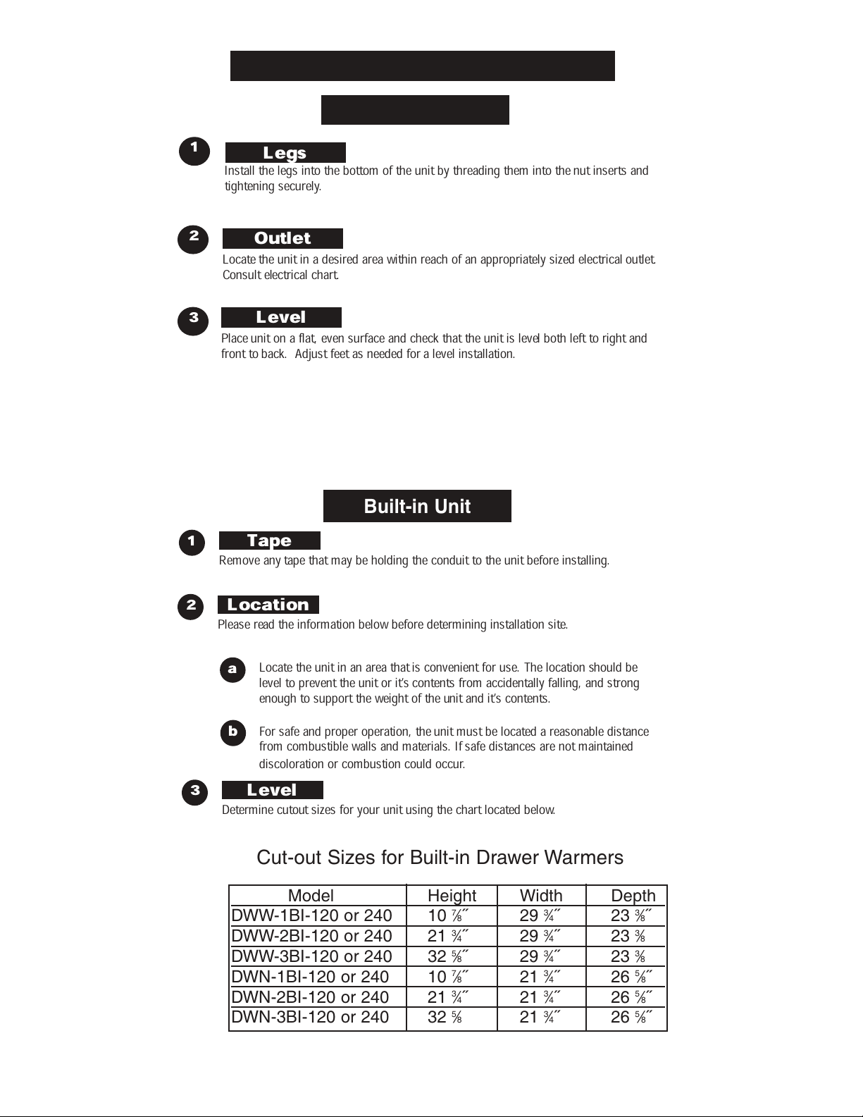
INSTALLATION INSTRUCTIONS
Freestanding Unit
1
2
3
Place unit on a flat, even surface and check that the unit is level both left to right and
front to back. Adjust feet as needed for a level installation.
Legs
Install the legs into the bottom of the unit by threading them into the nut inserts and
tightening securely.
Outlet
Locate the unit in a desired area within reach of an appropriately sized electrical outlet.
Consult electrical chart.
Level
CAUTION
LEGS MUST BE INSTALLED PRIOR TO THE OPERA-
TION OF THE UNIT. TO AVOID DAMAGE, DO NOT
LAY UNIT ON IT’S FRONT OR BACK SIDE.
Built-in Unit
1
Tape
Remove any tape that may be holding the conduit to the unit before installing.
2
Location
Please read the information below before determining installation site.
Locate the unit in an area that is convenient for use. The location should be
a
level to prevent the unit or it’s contents from accidentally falling, and strong
enough to support the weight of the unit and it’s contents.
For safe and proper operation, the unit must be located a reasonable distance
b
from combustible walls and materials. If safe distances are not maintained
discoloration or combustion could occur.
3
Level
Determine cutout sizes for your unit using the chart located below.
Cut-out Sizes for Built-in Drawer Warmers
Model Height Width Depth
DWW-1BI-120 or 240 10 7⁄8˝ 293⁄4˝ 233⁄8˝
DWW-2BI-120 or 240 21 3⁄4˝ 293⁄4˝ 233⁄8
DWW-3BI-120 or 240 32 5⁄8˝ 293⁄4˝ 233⁄8
DWN-1BI-120 or 240 10 7⁄8˝ 213⁄4˝ 265⁄8˝
DWN-2BI-120 or 240 21 3⁄4˝ 213⁄4˝ 265⁄8˝
DWN-3BI-120 or 240 32 5⁄8 213⁄4˝ 265⁄8˝
Page 3
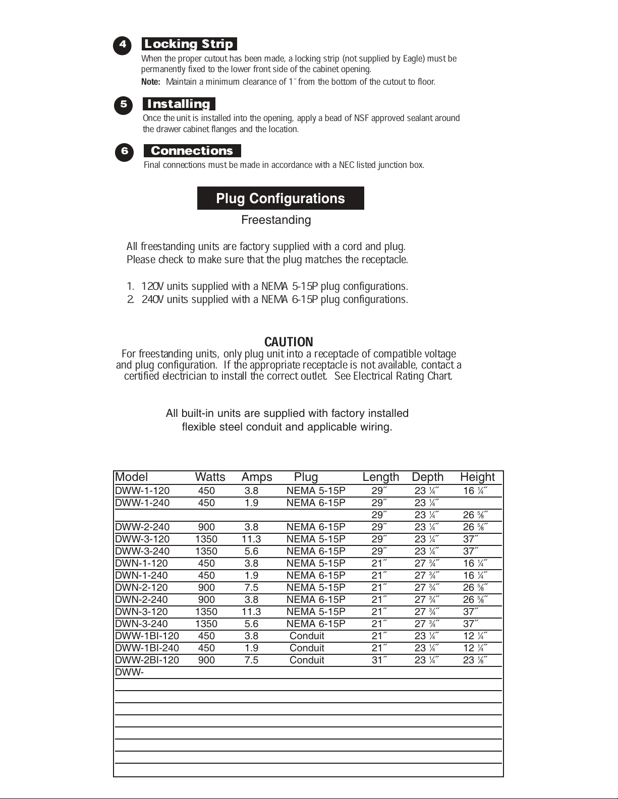
4
Locking Strip
When the proper cutout has been made, a locking strip (not supplied by Eagle) must be
permanently fixed to the lower front side of the cabinet opening.
Note:
Maintain a minimum clearance of 1˝ from the bottom of the cutout to floor.
5
Installing
Once the unit is installed into the opening, apply a bead of NSF approved sealant around
the drawer cabinet flanges and the location.
6
Connections
Final connections must be made in accordance with a NEC listed junction box.
Plug Configurations
Freestanding
All freestanding units are factory supplied with a cord and plug.
Please check to make sure that the plug matches the receptacle.
1. 120V units supplied with a NEMA 5-15P plug configurations.
2. 240V units supplied with a NEMA 6-15P plug configurations.
CAUTION
For freestanding units, only plug unit into a receptacle of compatible voltage
and plug configuration. If the appropriate receptacle is not available, contact a
certified electrician to install the correct outlet. See Electrical Rating Chart.
All built-in units are supplied with factory installed
flexible steel conduit and applicable wiring.
Electrical Rating Chart
Model Watts Amps Plug Length Depth Height
DWW-1-120 450 3.8 NEMA 5-15P 29˝ 23 1⁄4
DWW-1-240 450 1.9 NEMA 6-15P 29˝ 23 1⁄4˝ 161⁄4˝
DWW-2-120 900 7.5 NEMA 5-15P 29˝ 23 1⁄4˝ 265⁄8˝
DWW-2-240 900 3.8 NEMA 6-15P 29˝ 23 1⁄4˝ 265⁄8˝
DWW-3-120 1350 11.3 NEMA 5-15P 29˝ 23 1⁄4˝ 37˝
DWW-3-240 1350 5.6 NEMA 6-15P 29˝ 23 1⁄4˝ 37˝
DWN-1-120 450 3.8 NEMA 5-15P 21˝ 27 3⁄4˝ 161⁄4˝
DWN-1-240 450 1.9 NEMA 6-15P 21˝ 27 3⁄4˝ 161⁄4˝
DWN-2-120 900 7.5 NEMA 5-15P 21˝ 27 3⁄4˝ 265⁄8˝
DWN-2-240 900 3.8 NEMA 6-15P 21˝ 27 3⁄4˝ 265⁄8˝
DWN-3-120 1350 11.3 NEMA 5-15P 21˝ 27 3⁄4˝ 37˝
DWN-3-240 1350 5.6 NEMA 6-15P 21˝ 27 3⁄4˝ 37˝
DWW-1BI-120 450 3.8 Conduit 21˝ 23 1⁄4˝ 121⁄4˝
DWW-1BI-240 450 1.9 Conduit 21˝ 23 1⁄4˝ 121⁄4˝
DWW-2BI-120 900 7.5 Conduit 31˝ 23 1⁄4˝ 231⁄8˝
DWW-2BI-240 900 3.8 Conduit 31˝ 23 1⁄4˝ 231⁄8˝
DWW-3BI-120 1350 11.3 Conduit 31˝ 23 1⁄4˝ 34˝
DWW-3BI-240 1350 5.6 Conduit 31˝ 23 1⁄4˝ 34˝
DWN-1BI-120 450 3.8 Conduit 23˝ 26 3⁄4˝ 121⁄4˝
DWN-1BI-240 450 1.9 Conduit 23˝ 26 3⁄4˝ 121⁄4˝
DWN-2BI-120 900 7.5 Conduit 23˝ 26 3⁄4˝ 231⁄8˝
DWN-2BI-240 900 3.8 Conduit 23˝ 26 3⁄4˝ 231⁄8˝
DWN-3BI-120 1350 11.3 Conduit 23˝ 26 3⁄4˝ 34˝
DWN-3BI-240 1350 5.6 Conduit 23˝ 26 3⁄4˝ 34˝
˝ 16
1
⁄4
˝
Page 4

Page 5

1
Plug
On freestanding models, plug unit into an electrical outlet of the correct voltage,
size and plug configuration
.
2
3
Power
To turn the power on, turn the thermostat control to the desired temperature.
See chart below for Recommended Settings under food holding guide.
Pre-heat
Allow the unit 15-20 minutes to reach operating temperature. Moist applications
may require additional pre-heat time.
4
Vents
Adjust the drawer vents for desired humidity by loosening front drawer knob to
unlock the vent and slide the vent to desired location. Opening the vent all the way
allows maximum moisture to escape.
Food Holding Guide
Product Rec. Storage Temp. Heat Type Vent Control Capacity
Rolls, Hard 160-185˚F (71-85˚C) Dry closed 6-8 dz
Rolls, Soft 150-175˚F (66-79˚C) Moist open-half 6-8 dz
Vegetables 175-185˚F (66-85˚C) Moist open-half 3-3
Meat, Poultry 165-185˚F (74-85˚C) Dry closed 25-30 lbs. ribs
Fish 165-185˚F (74-85˚C Moist open
Casseroles 150-175˚F (66-79˚C) Dry closed
Pies, Desserts 160-185˚F (71-85˚C Dry closed
1
⁄2 dz potatoes
Care and Maintenance
To avoid injury, turn the power off and allow unit to cool before
cleaning or performing maintenance. On freestanding units,
unplug the electrical cord and/or turn off circuit breaker.
To preserve the finish of the drawer warmer, it is recommend-
ed that the surface be wiped daily with a damp cloth. Food
pans should be removed and washed. Stubborn stains may be
removed with a non-abrasive cleaner. Hard to reach areas
should be cleaned with a small brush and mild soap.
CAUTION
Abrasive cleaners could scratch the finish
of the drawer warmer.
Page 6

Care and Maintenance Continued
Removing Lime and Mineral Deposits
Note: If the water used has an excessive amount of lime or
mineral content, use the following instructions for periodic
cleaning and de-liming of the water pan.
1. Turn off the power. On freestanding units, unplug the
cord from the power source.
2. After the unit has cooled down, remove the water pan.
3. Fill the water pan with a mixture of water and delimer.
Allow the pan to stand with the mixture for the
recommended period of time. The time required will
depend on the solution used and the amount of deposits
in the pan. Check delimer manufacturer for specific
directions.
4. After the deliming period, drain the solution from the pan.
5. Continue to fill and rinse the pan with water only, until the
pan becomes clean.
6. Install the pan into the unit. On freestanding units, plug the
power cord into the receptacle and fill the pan as usual.
Wiring Diagram
Page 7

Parts List
 Loading...