

Page 1

C3600P AND C7200P
OPERATION INSTALLATION AND SERVICE MANUAL
PRECISION TON CONTAINER SCALES
EAGLE MICROSYSTEMS, INC.
366 Circle of Progress, Pottstown, PA 19464
610-323-2250 Phone - 610-323-0114 Fax
e-mail: infomicrosys@verizon.net
FILE NAME C3600 & C7200P MANUAL
1
Page 2

TABLE OF CONTENTS
CONTENTS PAGE
SECTION 1.0 DESCRIPTION..................................................................... 1
SECTION 2.0 PREPARATION FOR USE 3
2.1 RECEIVING INSPECTION 3
2.2 SHIPMENT 3
2.3 SITE SELECTION 3
2.4 INSTALLING 3
2.5 LEVELING 3
2.6 HOOK-UP CABLE 3
SECTION 3.0 OPERATION
SECTION 4.0 TROUBLE SHOOTING
SECTION 5.0 SERVICING
5.1 CHECKING THE CONNECTIONS
5.2 SERVICING THE LOAD CELL
5.3 CHECKING THE LOAD CELL
5.4 REPLACING THE LOAD CELL
SECTION 6.0 SPECIFICATIONS
SECTION 7.0 SPARE PARTS LIST
LIST OF ILLUSTRATIONS
FIGURE 1 C3600P AND C7200P DIMENSIONS
FIGURE 2 HOOK-UP CABLE TABLE
FIGURE 3 SUMMING BOARD CONNECTIONS
FIGURE 4 RESISTANCE TABLE
2
Page 3
SECTION 1.0 DESCRIPTION
The Eagle Microsystems C3600P and C7200P Precision Ton Container Scales are designed specifically
for the water and wastewater industry. They incorporate 4 stainless steel shear beam load cells with
integral overload stops. The C3600P and C7200P are supplied with the required amount of rollers for
easy rotation of ton containers. Each scale is supplied with 15' of cable. Additional lengths are available
upon request.
The mechanical overload stop and the shock isolation pad prevents damage to the load cell when placing
ton containers on the scale.
C7200P WT3600
SECTION 2.0 PREPARATIO N FOR USE
2.1 RECEIVING INSPECTION
1. Upon receiving the scale, carefully inspect the condition of the crate including the banding
and any protective covering used for shipping. Report any damage to the shipper and to
Eagle Microsystems.
2. Remove the scale from crating and inspect for damage. Report any damage to the shipper
and to Eagle Microsystems.
2.2 SHIPMENT
Should re-shipment of your scale become necessary.
1. Use a strong, well built crate. The crate must be larger than the outer dimensions of the
scale to protect it in shipping.
2. Make sure the hook-up cable is protected and secured in crate.
3
Page 4

3. Use strong banding to secure scale in shipment.
2.3 SITE SELECTION
1. Extreme temperature variations may cause the scale to drift slightly off zero. Your precision
ton container scale has temperature compensated load cells to minimize such effects.
However, whenever possible, avoid placing your scale near air ducts, heating or cooling
elements, doors opening to the outside, ect. to minimize temperature effects.
2. Line power devices causing large inductive currents should not run off the same circuit as
the scale. Fluctuations in line voltage caused by such devices may result in display instability.
3. The hook-up cable to the read-out should not run close to other unshielded cables. Display
instability may result.
4. For best accuracy, a flat, level, and rigid surface is recommended to support the scale and ton
containers.
5. The area should be accessible for periodic cleaning.
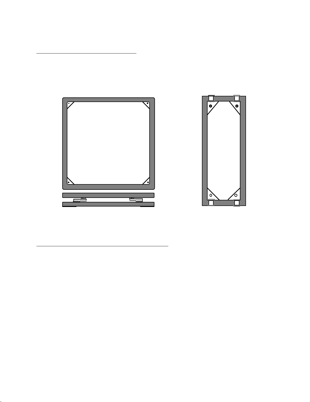
2.4 INSTALLING
1. Clean the site area of dirt and debris.
2. Locate and mark all four corners. See Figure 1 for bolt/stud locations.
3A 1/2" to 5/8" diameter bolt/stud is suggested. The bolt/stud should protrude 2" above ground.
4. Set scale into place.
52"
52"
FIG. 1
2.5 LEVELING
1. For best scale performance scale should be level within 1/2 degree.
2. Check all corners for wobble and shim if required.
4
Page 5

3. Using wrench to tighten all corners
2.6 HOOK-UP CABLE
Figure 2 shows the wiring connections necessary to attach the platform to the read-out instrument. The
color code and function are as noted. Consult read-out manual for the required information for its hookup.
(Most scales are shipped with mating connector for easy hook-up to the instrument supplied)
COLOR CODE FUNCTION
BLACK – EXCITATION
WHITE – SIGNAL
RED + EXCITATION
GREEN + SIGNAL
YELLOW SHIELD
FIG. 2
SECTION 3.0 OPERATION
Follow the instrument's manual for correct power-up instructions.
The C3600P and C7200P Ton Container Scales are relatively simple devices. Once the operation of the
instrument is understood, the ton containers are simply placed on the rollers that are provided. Listed are
a few helpful points to follow when using Eagle Microsystems scales.
1. Always place the ton container in the approximate center of the scale
2. Place the ton containers on the scale. Do not drop them. Although the scale is designed to
withstand impact loads, care should be taken to avoid accidents.
SECTION 4.0 TROUBLE SHOOTING
The following is a list of potential problems and likely cures.
1. Inaccurate but repeatable weight readings:
a. Adjust span on read-out (see instrument manual)
2. Blank or drifting display:
a. Consult the instrument manual.
b. Look for loose connection in hook-up cable at the instrument or in the Summing Box.
See Section 5.1
d. Look for moisture in the Summing Box
c. Test for bad load cell (see section 5.2)
SECTION 5.0 SERVICING
5.1 Checking the connections to the Summing Box.
1. Locate the Summing Box on the bottom frame and remove the cover. (4 screws)
2. View and compare all connections to Figure 3.
5
Page 6

3. Check all connections by lightly pulling on each lead. Tighten terminal connections as
needed.
4. If problem persists, press lightly on the circuit board itself and check meter response.
Replace board if required.
Note: Make sure when replacing the cover that the box is dry and the cover is tight.
SJB4-S
5.2 Checking the load cells.
1. Load Cell resistance test:
a. Disconnect the load cells from the Summing Box and measure the resistance as shown in
Figure 4.
b. Any electrical leakage between the leads and the load cell case is usually caused by moisture
leakage into the load cell or by moisture in a damaged load cell cable.
c. If a load cell does not pass the above resistance tests, replace it with a known good one.
2. Load Cell zero shift test:
a. Remove the top frame of the scale. (see section 5.3)
b. Connect a DC power supply of 10 or 15 volts to the Red (+) and Black (-) excitation load cell
leads.
c. The measured output between the Green (+) and White (-) signal leads should be less
than 5 millivolts.
d. An output signal greater than 5 millivolts indicates a zero shift caused by mechanical
overload.
e. If the output signal is between 5 and 15 millivolts, the load cells zero has shifted but will
probably still continue to work.
f. If the output signal is greater than 15 millivolts, the load cell should be replaced with a
known good one.
-E
+E
+E
-S
+S
SH
R1 R1
R1
R1R1
-
+
-SIG
-EXT
+SIG
-E
-S
+S
SH
+EXCT
EAGLE MICROSYSTEMS
SHLD
-E
-S
+S
+E
-E
+E
SH
-S
SH
+S
FIG. 3
NOTE: If the load cell's zero has shifted due to a mechanical overload, the reason for the
overload should be determined before a new load cell is installed.
5.3 REPLACING THE LOAD CELL
Call the factory to advise that the load cell is defective. Report model and serial numbers for both load cell
and scale.
1. Remove all ton containers from scale.
2. Remove plastic caps from top frame.
3. Use 3/4" deep socket to remove hex nuts inside top frame on all four load cells .
6
Page 7

TC-SC
4. Set top frame aside.
5. Remove the 4 screws from Summing Box lid. Disconnect the wires of defective load cell
being replaced. Gently pull cable out of the bottom frame.
6. Use hex wrenches to remove 2 socket head cap screws which secure load cell to frame.
7. Save the overload rod.
8. Install new load cell using 35 ft. lbs. torque to screws and fish wires back to the Summing Box.
9. Insert leads into terminal as before and tighten. Put lid on Summing Box and tighten.
10. Install overload rod with 1/8" gap to frame. Add shock pad.
11. Put top frame back onto load cells. Add flat washer, lock washer and hex nut.
12. With a screw driver, adjust overload rod to 0.018" gap with feeler gage. Tighten hex nut
SECTION 6.0 SPECIFICATIONS
PHYSICAL SIZE: Model C3600P: 24" X 60" X 10"
Model C7200P: 60" X 60" X 10"
WEIGHT: Model C3600P: 235#
Model C7200P: 340#
CONSTRUCTION: Welded steel box tubing frame.
FINISH: All parts are stainless steel, plastic, or painted with acrylic
urathane paint.
CAPACITY: Model C3600P: 4,000#
Model C7200P: 8,000#
SAFE OVERLOAD: 200% of Rated Capacity.
ULTIMATE OVERLOAD: 400% of Rated Capacity.
NOMINAL OUTPUT: Model C3600P: 1.0 mV/V at 4,000#
Model C7200P: 1.2 mV/V at 8,000#
7
Page 8

OPERATING ACCURACY: 0.1% of Capacity.
REPEATABILITY: 0.02% of Capacity.
LOAD CELLS: 4 stainless steel strain gage shear beams, 350 ohms.
SIGNAL CABLE: 15' of 6 conductor color coded shielded cable. PVC jacket.
SECTION 7.0 SPARE PARTS LIST
PART DESCRIPTION MODEL/CAPACITY INH P/N
S.S. Load Cell C3600P / 3,000# 500337
S.S. Load Cell C7200P / 5,000# 500088
S.S. Stop Rod C3600P / C7200P 400186
S.S. 1/2-20 Hex Nut C3600P / C7200P 615006
S.S. 1/2 Flat Washer C3600P / C7200P 615007
S.S. 1/2 Lock Washer C3600P / C7200P 615008
S.S. 1/2-20 X 1 3/4 S.H.C.S. Mounting bolt C3600P / C7200P 615003
Shock Pad (2" X 1.5" X .75") C3600P / C7200P 400014
Plastic Roller C3600P / C7200P 400132
S.S. Roller Axle C3600P / C7200P 400022
S.S. Retaining Ring C3600P / C7200P 670131
Plastic Plug C3600P / C7200P 650020
15' of 6 Conductor Cable C3600P / C7200P 500061
Summing Box SJB-4-S (complete) C3600P / C7200P 110143
Summing Board only SJB-4-S C3600P / C7200P 110048
8
 Loading...